Creating a Floor plan, Footing detail and Isometric view using AutoCad
Aim: To create a floor plan, Footing details, and isometric view using AutoCAD
Introduction: The floor plan, footing details, and isometric view are drafted using the AutoCAD 2016
Q-1 -To draw the figure C1 of C.S. of load-bearing wall overspread footing
Procedure:
Type “REC” in the command bar and press enter
Specify first corner point or [Chamfer/Elevation/Fillet/Thickness/Width]: 1,1
Specify other corner point or [Area/Dimensions/Rotation]: @0.9,0.25
Type “REC” in the command bar and press enter
Specify first corner point or [Chamfer/Elevation/Fillet/Thickness/Width]: 1.2,1.25
Specify other corner point or [Area/Dimensions/Rotation]: @0.5,0.4
Type “REC” in the command bar and press enter
Specify first corner point or [Chamfer/Elevation/Fillet/Thickness/Width]: 1.25,1.65
Specify other corner point or [Area/Dimensions/Rotation]: @0.4,0.4
Type “REC” in the command bar and press enter
Specify first corner point or [Chamfer/Elevation/Fillet/Thickness/Width]: 1.3,2.65
Specify other corner point or [Area/Dimensions/Rotation]: _u
2D point or option keyword required.
Specify other corner point or [Area/Dimensions/Rotation]: _u
2D point or option keyword required.
Specify other corner point or [Area/Dimensions/Rotation]: *Cancel*
Type “REC” in the command bar and press enter
Specify first corner point or [Chamfer/Elevation/Fillet/Thickness/Width]: 1.3,2.05
Specify other corner point or [Area/Dimensions/Rotation]: @0.3,0.6
Command: Regenerating model.
Type “REC” in the command bar and press enter
Specify first corner point or [Chamfer/Elevation/Fillet/Thickness/Width]: 1.3,2.65
Specify other corner point or [Area/Dimensions/Rotation]: @0.3,0.05
Type “REC” in the command bar and press enter
Specify first corner point or [Chamfer/Elevation/Fillet/Thickness/Width]: 1.3,2.65
Specify other corner point or [Area/Dimensions/Rotation]: @0.3,1
Type “REC” in the command bar and press enter
Specify first corner point or [Chamfer/Elevation/Fillet/Thickness/Width]: 1.6,2.05
Specify other corner point or [Area/Dimensions/Rotation]: @1.5,0.6
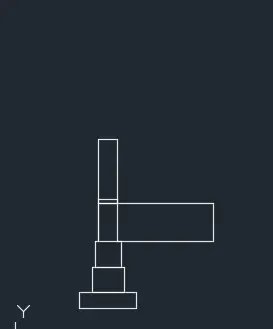
Type “REC” in the command bar and press enter
Specify first corner point or [Chamfer/Elevation/Fillet/Thickness/Width]: 1.25,2.05
Specify other corner point or [Area/Dimensions/Rotation]: @-1.15,-0.15`
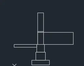
Now type “PLINE” or “Pl” in the command bar and press enter
Specify start point:
Keep ortho on and select the top corner of the last formed rectangle
Current line-width is 0.0000
Specify next point or [Arc/Halfwidth/Length/Undo/Width]: @0.3,0
Specify next point or [Arc/Close/Halfwidth/Length/Undo/Width]: @0,0.15
Specify next point or [Arc/Close/Halfwidth/Length/Undo/Width]: @0.3,0
Specify next point or [Arc/Close/Halfwidth/Length/Undo/Width]: @0,0.15
Specify next point or [Arc/Close/Halfwidth/Length/Undo/Width]: @0.3,0
Specify next point or [Arc/Close/Halfwidth/Length/Undo/Width]: @0,0.15
Specify next point or [Arc/Close/Halfwidth/Length/Undo/Width]: @0.3,0
Specify next point or [Arc/Close/Halfwidth/Length/Undo/Width]: *Cancel*
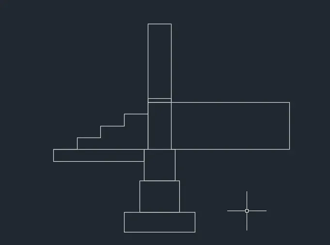
And now type “Tr” in command and press double enter and delete the unwanted line
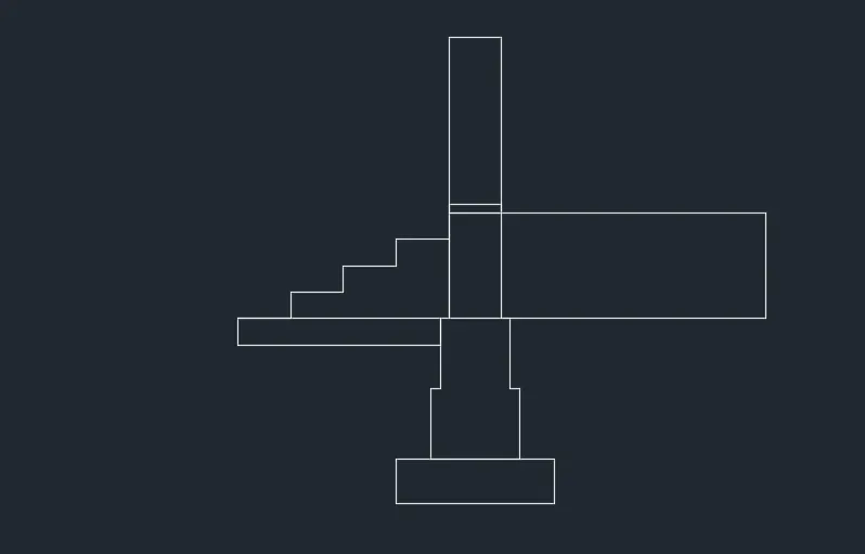
Now type “Dim” in command and press double enter and give the dimensions
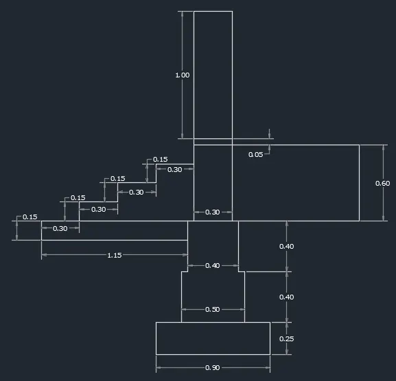
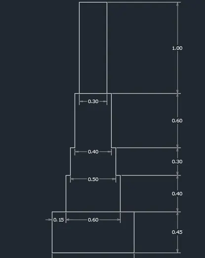
Q-2-To draw the figure C4 of C.S. of the load-bearing wall showing foundation details
Type “REC” in the command bar and press enter
Specify first corner point or [Chamfer/Elevation/Fillet/Thickness/Width]: 0,0
Specify other corner point or [Area/Dimensions/Rotation]: @0.9,0.45
Type “REC” in the command bar and press enter
Specify first corner point or [Chamfer/Elevation/Fillet/Thickness/Width]: 0.15,0.45
Specify other corner point or [Area/Dimensions/Rotation]: @0.6,0.4
Type “REC” in the command bar and press enter
Specify first corner point or [Chamfer/Elevation/Fillet/Thickness/Width]: 0.2,0.85
Specify other corner point or [Area/Dimensions/Rotation]: @0.5,0.3
Type “REC” in the command bar and press enter
Specify first corner point or [Chamfer/Elevation/Fillet/Thickness/Width]: 0.25,1.15
Specify other corner point or [Area/Dimensions/Rotation]: @0.4,0.6
Type “REC” in the command bar and press enter
Specify first corner point or [Chamfer/Elevation/Fillet/Thickness/Width]: 0.3,1.75
Specify other corner point or [Area/Dimensions/Rotation]: _u
2D point or option keyword required.
Specify other corner point or [Area/Dimensions/Rotation]: _u
2D point or option keyword required.
Specify other corner point or [Area/Dimensions/Rotation]: *Cancel*
Type “REC” in the command bar and press enter
Specify first corner point or [Chamfer/Elevation/Fillet/Thickness/Width]: 0.3,1.75
Specify other corner point or [Area/Dimensions/Rotation]: @0.3,1
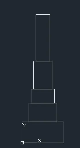
And now type “Tr” in command and press double enter and delete the unwanted line
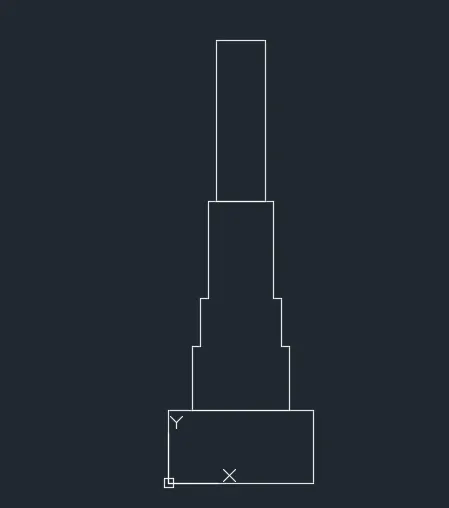
Now select the footing and move it from the origin and
now type “Dim” in command and press double enter and give the dimensions
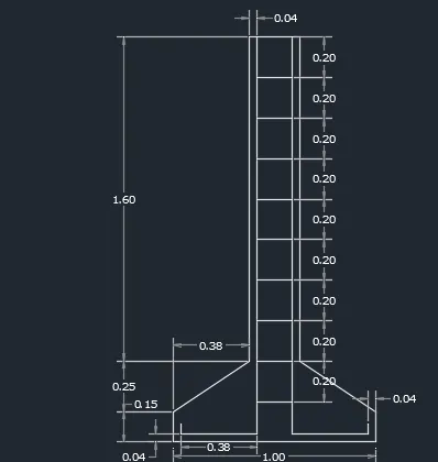
Q-3-To draw figure C2 of C.S of ISOLATED FOOTING
Type “L” in the command bar and press enter
Specify first point: 0,0
Specify next point or [Undo]: 0,0.15
Specify next point or [Undo]: 0.38,0.40
Specify next point or [Close/Undo]: 0.38,2
Specify next point or [Close/Undo]: 0.42,2
Specify next point or [Close/Undo]: 0.42,0.04
Specify next point or [Close/Undo]: 0.04,0.04
Specify next point or [Close/Undo]: 0.04,0.08
Specify next point or [Close/Undo]: *Cancel*
Type “L” in the command bar and press enter
Specify first point: 0,0
Specify next point or [Undo]: 1,0
Specify next point or [Undo]: 1,0.15
Specify next point or [Close/Undo]: 0.62,0.40
Specify next point or [Close/Undo]: 0.62,2
Specify next point or [Close/Undo]: 0.58,2
Specify next point or [Close/Undo]: 0.58,0.04
Specify next point or [Close/Undo]: 0.96,0.04
Specify next point or [Close/Undo]: 0.96,0.08
Specify next point or [Close/Undo]: *Cancel*
Type “L” in the command bar and press enter
Specify first point: 0.42,2
Specify next point or [Undo]: 0.58,2
Specify next point or [Undo]: *Cancel*
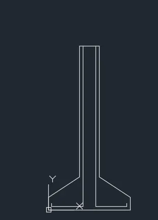
Type “o” (offset) in the command bar and press enter
now select the last line and make offsets @ 0.2 from the last line drawn
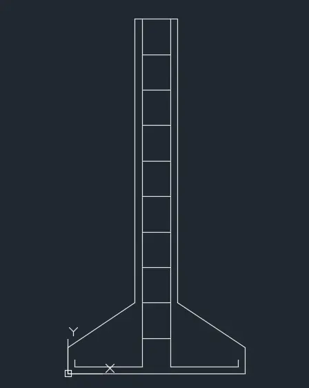
Now select the footing and move it from the origin and
now type “Dim” in command and press double enter and give the dimensions
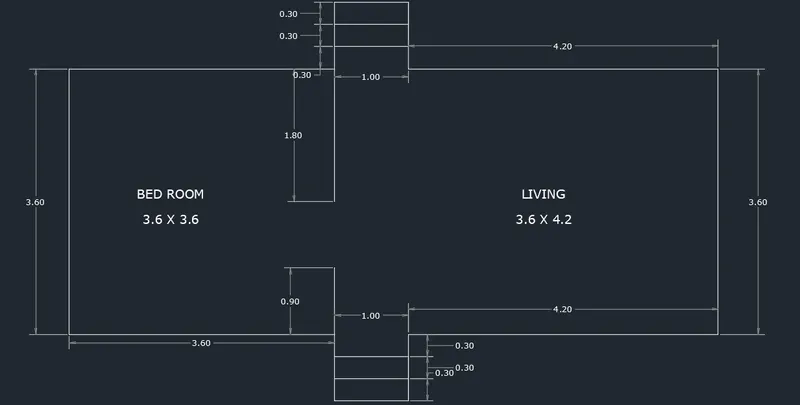
Q-4-To draw the figure C3 of C.S of line diagram of a two-bedroom building
Type “REC” in the command bar and press enter
Specify first corner point or [Chamfer/Elevation/Fillet/Thickness/Width]: 1,1
Specify other corner point or [Area/Dimensions/Rotation]: @8.8,3.6
Type “REC” in the command bar and press enter
Specify first corner point or [Chamfer/Elevation/Fillet/Thickness/Width]: 4.6,1
Specify other corner point or [Area/Dimensions/Rotation]: @1,-0.9
Type “REC” in the command bar and press enter
Specify first corner point or [Chamfer/Elevation/Fillet/Thickness/Width]: 4.6,4.6
Specify other corner point or [Area/Dimensions/Rotation]: @1,0.9
Type “L” in the command bar and press enter
Specify first point: 4.6,1
Specify next point or [Undo]: @0,0.9
Specify next point or [Undo]: *Cancel*
Type “L” in the command bar and press enter
Specify first point: 4.6,4.6
Specify next point or [Undo]: @0,-1.8
Specify next point or [Undo]: *Cancel*
Now type “X” in the command bar to explode the required rectangle
Now Type “o” in the command bar and press enter
now select the required line and make offsets @ 0.3
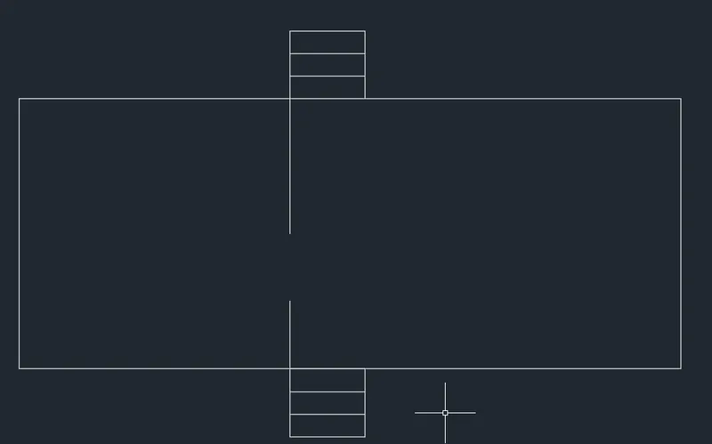
And now type “Tr” in command and press double enter and delete the unwanted line
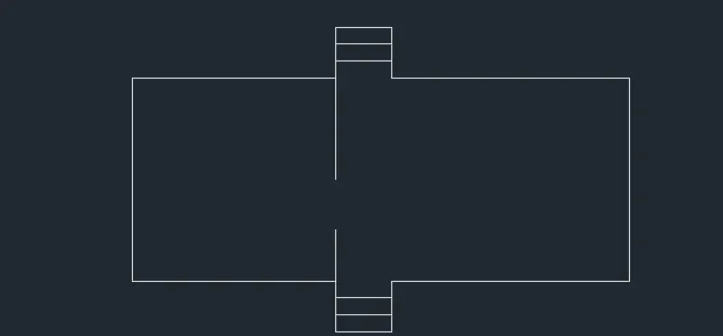
now type “Dim” in command and press double enter and give the dimensions
now type “T” in the command bar and press enter to type text
Q-5-To draw an isometric view of steps
In this part, we are going to create an Isometric view of the steps
-First, check the dimension before start
-Click on "Isometric drafting" to create an Isometric view
-Next start with a "L" line command.
-Draw a line as per dimension.
-In Isometric we have 3 options to draw
-The Isometric Right, Isometric left, Isometric Top to draw the line.
-Isometric Right goes in Right, top and Straight
-Isometric Left goes in Left, top and Straight
-Isometric Top goes in Right, Left, and Top
Here, we start
LINE keep iso left plane
Specify first point: anywhere on the screen
Specify next point or [Undo]: 1 towards -x
Specify next point or [Undo]: 0.15 -y
Specify next point or [Close/Undo]: 1+x
Specify next point or [Close/Undo]:0.15+y
Specify next point or [Close/Undo]: <Isoplane Top> 0.3
Specify next point or [Close/Undo]: 1 towards left
Specify next point or [Close/Undo]:0.3
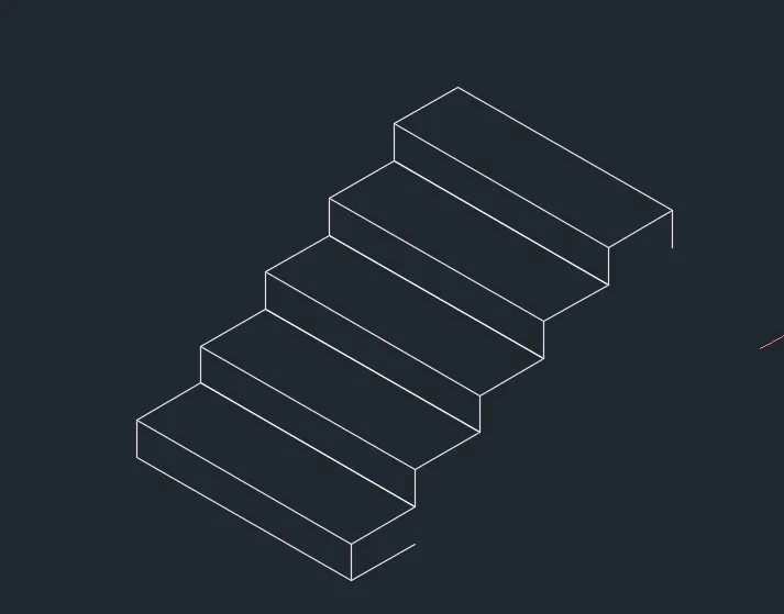
Now we should copy the formed image and paste it till we get 5 steps while copying we should keep ortho off
After copying the steps join the corners by keeping ortho off so that we can get our desired image
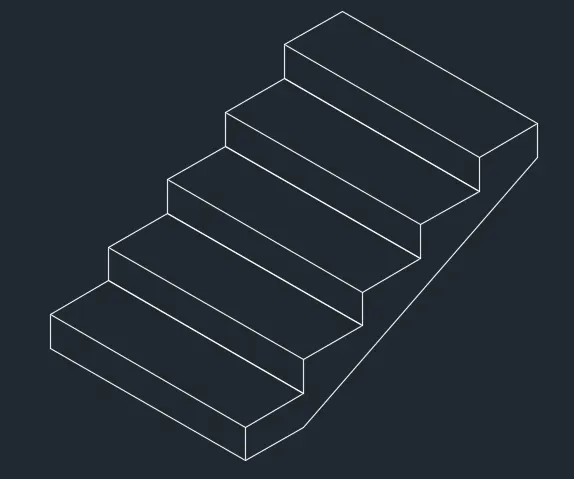
now type “Dim” in command and press double enter and give the dimensions
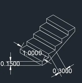
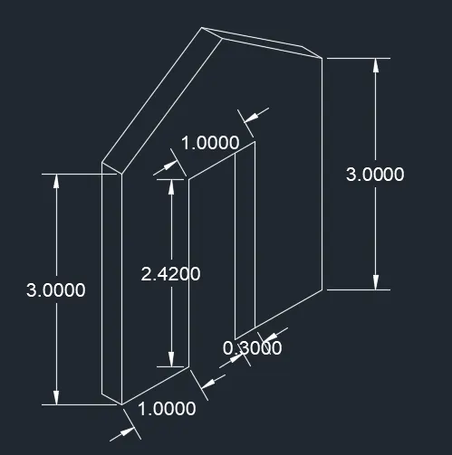
Q-6-to draw the figure C-6 of the Isometric view of the Gable wall
- Keep the plane in iso -right and give L in command and give 1 unit towards right
-Now change the plane into iso-left and give L command and give 3 units upwards and 0.3 units left and 3 units down and 0.3 units left.
-Now press ESC
-Now keep the plane iso -right take L command and draw a line 2.42 units upwards from the point where we start the drafting and 1 unit towards the right and 2.42 units downwards now by using iso-left again 0.3units towards left and 2.42 units upwards and press ESC
-Now by using iso-right with the L command draw 1 unit towards the right from the door in the fig and 3 units upwards and press ESC.
-Now give L command and from the point where we start take 0.5 units towards right and 4 units upwards now change the plane and draw 0.3 line to the left now press ESC.
-Now join the top edges of the figure using line by keeping ortho off
-Here we get the desired image
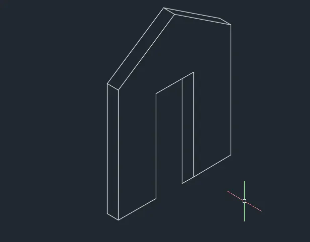
now type “Dim” in command and press double enter and give the dimensions