Creating various 3D Models like Furniture, Footing, Girder, Column drop with panel and Gable Wall in AutoCad
1 ans:
Aim: To create a 3D Furniture elements as given in the figure and need to assume dimensions that are missing in the drawing.
PROCEDURE:
- First we have to open the AutoCAD 3d and need to set the units
- Next we have to enter the UCS command and adjust ucs icon on the screen.
- After setting the ucs on the screen we need to draw the line with the length of 3'.
- Next draw the line from the previous line upwards with the length of 2'-6".
- Again draw the line from the previous line with the length of 3' horizontally.
- Next we draw the line from the first line and last line to close the rectangle.
- Next we have to use the extrude command to extrude the rectangle towards back with the length of 2'.
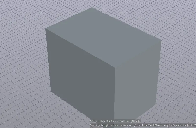
- Next we draw the rectangle inside the extruded box as shown
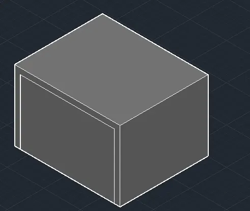
- Next we have to extrude inside rectangle with the length of 1'10"
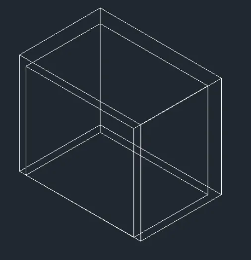
- Next we substract the inside box from the outer box using the substract command
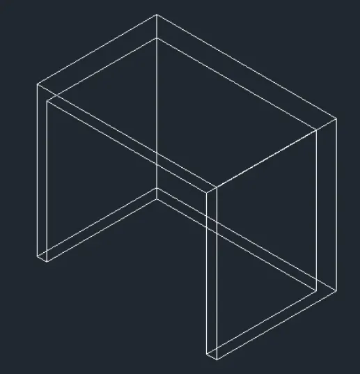
- Next we have to change the visual style to hidden
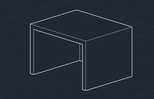
- Next we put dimensions as shown
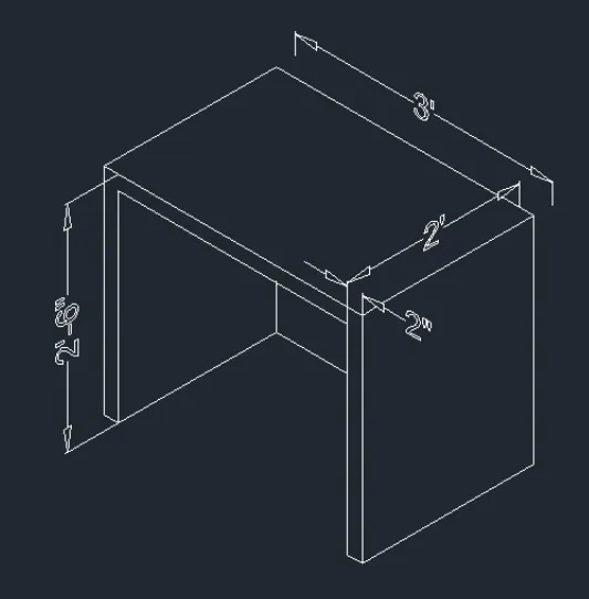
Result:
2ans:
Aim: To draw the 3d model of isolated footing
PROCEDURE:
- First we have to open the AutoCAD 3d and set the units using the units command.
- Next select the dimstyle command and select primary units as architectural.
- Next we use the ucs command to set the directions of x-axis, y-axis aid z-axis.
- Next we draw the rectangle using the line command with the size of 3' x 3'.
- Now we draw an rectangle of size 1'x1' in the center of of outer
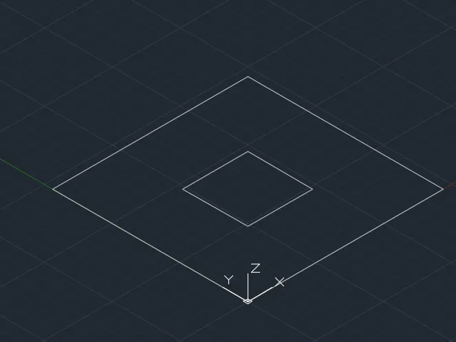
- Now move the center rectangle at a distance of 2'6"
- Now create region using region command to both rectangles as shown
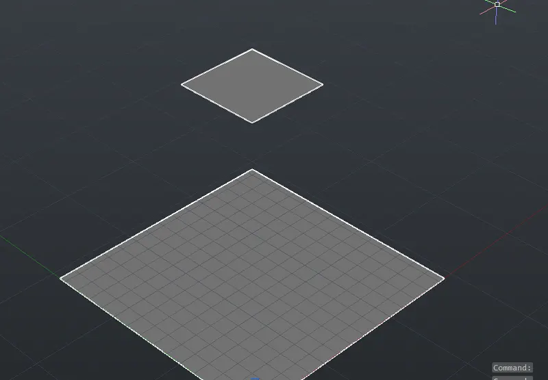
- Now extrude the larger rectangle at a height of 6" as shown
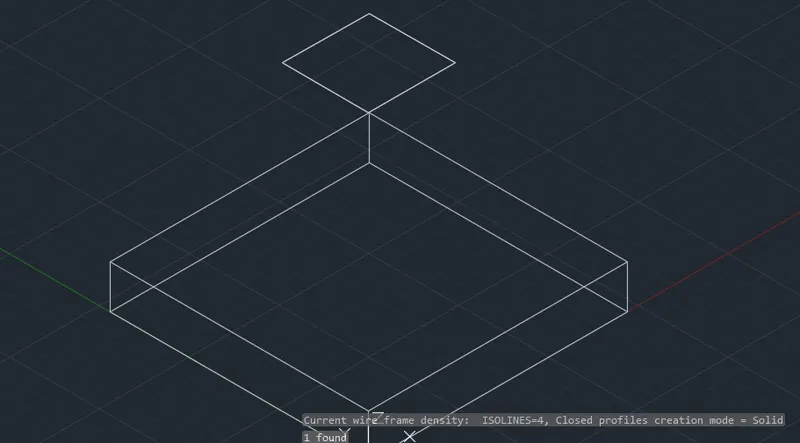
- Now join the edges of small and large extruded rectangle as shown
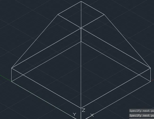
- Now add 3dfaces for all 4 sides using 3d face command as shown
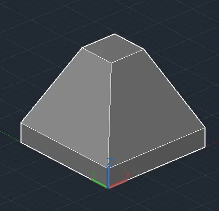
- Now change the vision style to hidden and give dimensions as shown
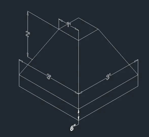
Result:
3ans:
Aim:To create the 3D model of AASTHO Type Grider
- First we have to open the 3d AutoCAD and set the units using the units command.
- Next we use the ucs command to set the directions of x-axis, y-axis aid z-axis.
- Next we have to draw the horizontal line with the length of 1'-4".
- Next we draw the inclined line from the previous line.
- Next from the previous line we have to draw the another vertical line upwards with the length of 6".
- Next again we draw the line from the previous line with the angle of 135 degrees with the length of 8".
- Draw the vertical line from the previous line with the length of 1'-3".
- Next we draw another line from the previous line with the angle of 45 degrees with the length of 4".
- Next draw a vertical line from the previous line with the length of 6".
- Next we use the mirror command and press enter, then select right portion and place a cursor at the middle of the first line, then automatically right side portion will be mirrored to the opposite side
- And now filet the edges at fillet radius 1" in down as shown in the below figure.
- Now add 3d face to the figure using 3dface command
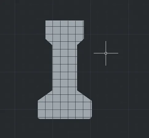
- Now by using Extrude command Extrude the figure 10'
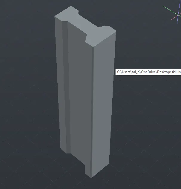
- Now give dimensions as shown
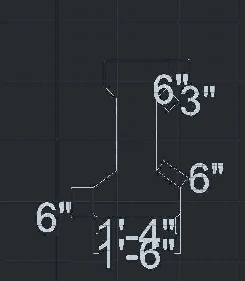
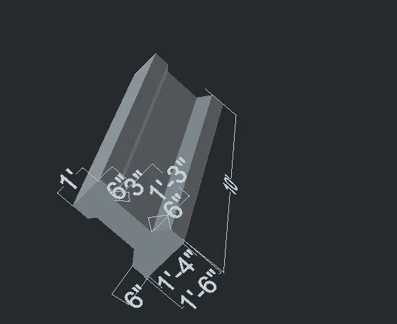
Result:
4 ans:
Aim: To create the 3D model of drop column with panel
- First we have to open the AutoCAD 3d and set the units using the units command.
- Next we use the ucs command to set the directions of x-axis, y-axis aid z-axis.
- Create a circle of radius 1'6" in the top view
- Now create a region for the circle and extrude it with 10'
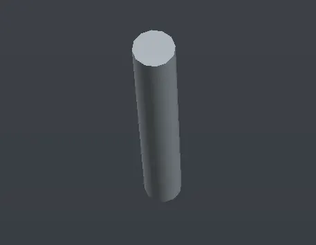
- Now create a cone by using cone command-click diameter and give 1'6" now give top radius and give the 1'6" and give height as 1'.
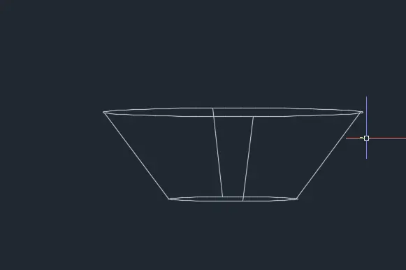
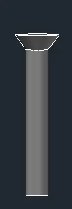
- Now place the cone on the top of the extruded circle as shown in the figure
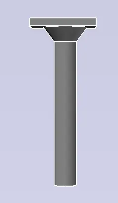
- Now keep the view on top and draw a rectangle of dimensions 4'6"x4'6".Extrude it 6"
- In the top view, by using the move command Place the rectangle at the center of the cone and also adjust the placement of the rectangle in the front view also the drawn rectangle is at the bottom of the circle so we have to move it to the top as shown.
- Now give dimensions as shown
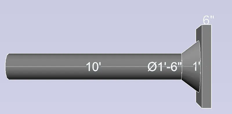
Result:
5 ans:
Aim:To create a 3D model of a wall
- First we have to open the AutoCAD 3d and set the units using the units command.
- Next, we use the ucs command to set the directions of the x-axis, y-axis aid z-axis.
- Next we need to draw horizontally forward with the length of 10'.
- Next we draw another line vertically upwards with the length of 10'
- Now draw the vertical line of height 12'6" on other end of horizontal line
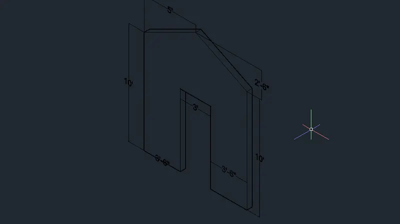
- Now take offset of 5' from any vertical line
- Now draw a horizontal line from 12'6" vertical line passing through offset line
- Now join the intersecting point in the middle from 10' line and draw a 10' line on the 12'6" line and join the intersecting point as shown
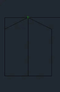
- Now delete all extra line make the figure as shown
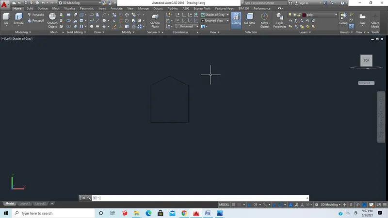
- Now start a rectangle of width 3' and height 7' at 3'6" from the left end or right end
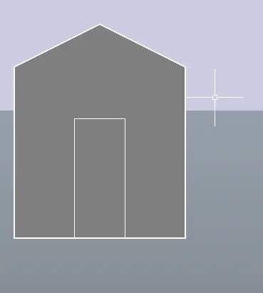
- Now extrude both outer border and inner rectangle at 9" as shown
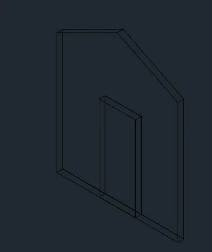
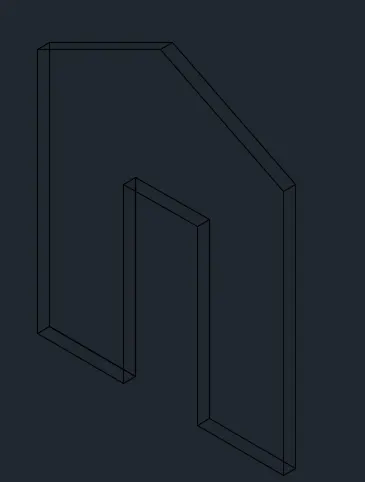
- Now subtract the rectangle from the image by using subtract command as shown
- Now give dimensions
Result:
Final Result: