Wiring harness design in CATIA V5 - 3D modeling Week 2 Challlenge
Converting Standard component into Electrical component
Follow the steps below to define a standard component as Electrical one :
- Create or download the 3D part as requirement. We can download these parts from vendor sites in .igd or .step format. Here, we are taking a 3D part of a connector (C-DT06-08SA)
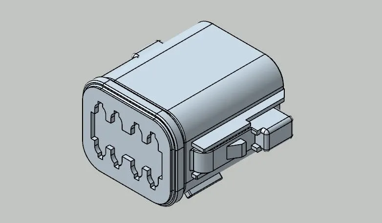
- Identify the component and decide the bundle entry face and mating face with respective counter part of connector.
- Next steps are to create Geometrical parametres.
- Create a point in centre of the face as shown. This is the Bundle Connection Point.
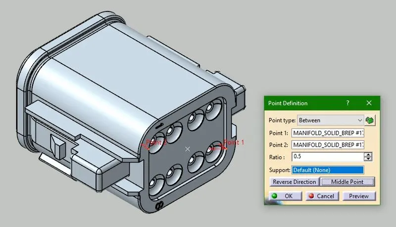
- Create another point in centre of the face on the mating side too. This is the Connector Connection Point.
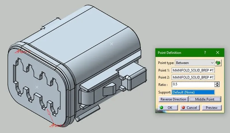
- Add an Axis System at Connector Connection Point.
- Make sure Y-axis stays normal to the mating face and X-axis stays in line with clips (locker).
- Axis system plays a very important role while assembling the components together.
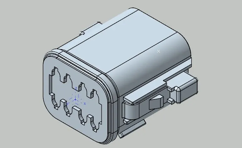
- After creating Geometrical parametres, next step is to define the component electrically.
- Switch to Electrical Part Design workbench and as this part is a connector, click on Define Connector Feature and click on the component.
- Here, a single bundle connects to the component so select 'Select Insert Connector'.
- Part number, we can keep default or change as needed.
- Identify the number of terminals provided in the component and add the number and click OK.
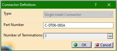
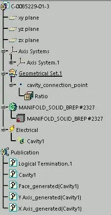
- Feature Tree will show the defined electrical component and terminals into it.
- Now define the electrical parametres.
- Click on Bundle connection point feature and the below shown box will open.
- Select the first face that is normal to the bundle entry direction as 'Representation'.
- Select the Bundle Connection Point as 'Point'.
- Select the first face that is normal to the bundle entry direction as 'Initial Condition' and hit OK.
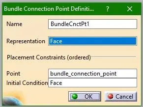
- Feature Tree will show the defined Bundle Connection Point and the electrical parametres of it.
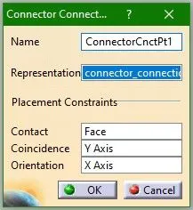
- Now, click on Connector connection point feature.
- Select Conector connection point as 'Representation'.
- Select the mating face as 'Contact'.
- Y-axis will be the 'Coincidence' and X-axis as 'Orientation'.
- If a connector has Cavity point, then it is needed to define cavity parametres too. Here the connector has no such feature, so now this is fully defined as a Electrical component.
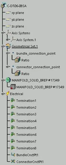
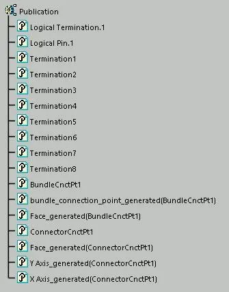
- Same steps we will follow to define another Electrical Component.
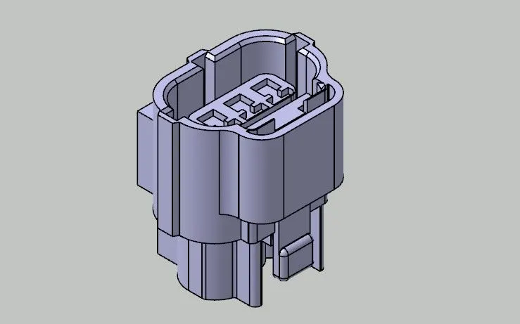
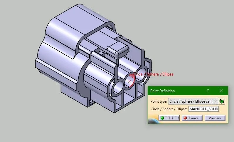
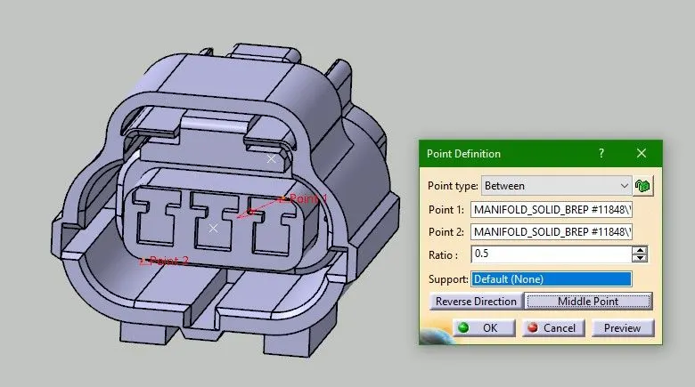
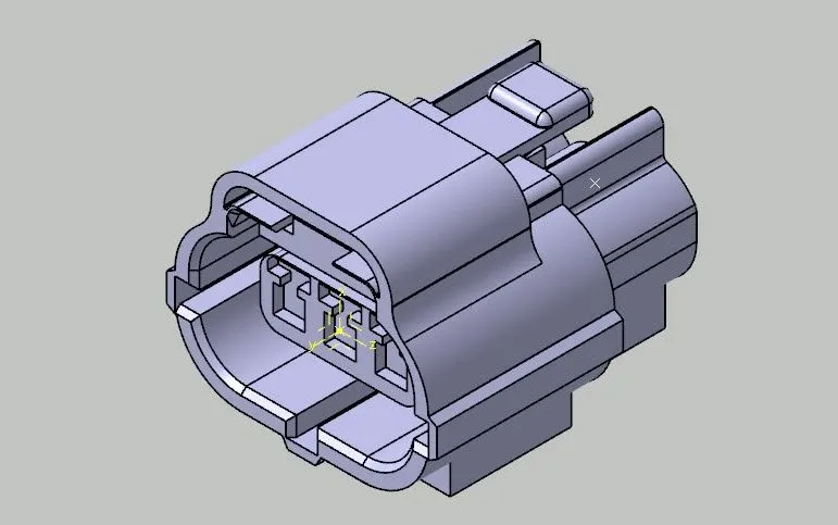
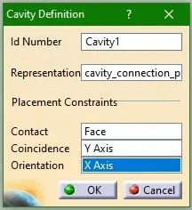
- Here the connector is provided with mounting feature, so we will define cavity connection point too.
- Add a point at mating face edge and an Axis System on it.
- Keep the axes in the same orientation as mating face axis system.
- Define the point later in Electrical Part Design workbench.
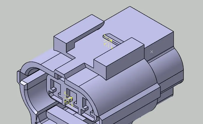
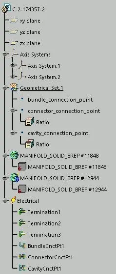
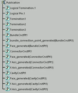
- Connector mounting device / Connector Cavity
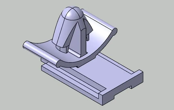
- Add a point, that will be coincident to the Cavity Connection Point defined on connector.
- Add an Axis System in the same orientation as defined on connector. If it is not oriented same way, it can create a problem in assembly.
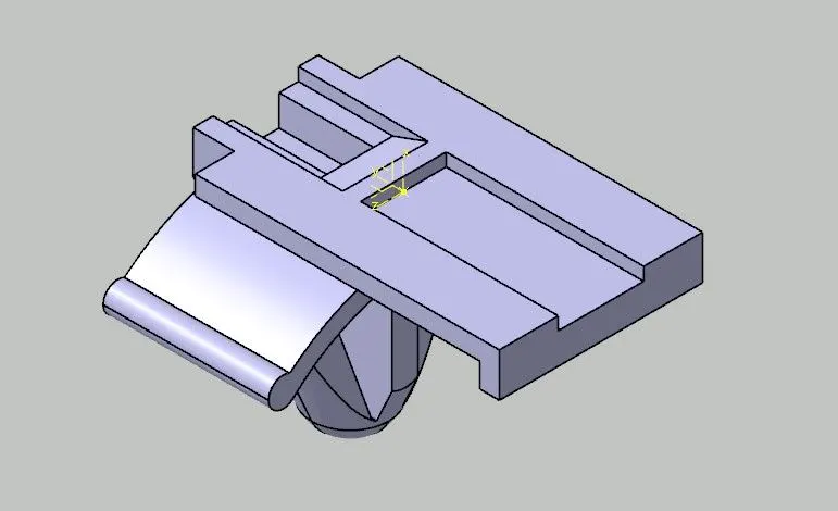
- Switch to Electrical Part Design workbench and define the component as Mounting Equipment.
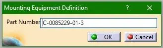
- Make sure to define the point as Cavity and not Cavity connection point.
- Select the point as 'Representation'.
- Select mating face as 'contact'.
- Y-axis will be the 'Coincidence' and X-axis as 'Orientation'.