Roof challenge
ROOF DESIGN
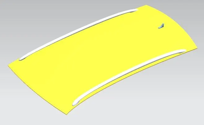
OBJECTIVE : The aim of this project is to design required flanges and reinforcements for a provided dumb body in the form of outer roof part. We will also study the curvature structure and do analysis of the design.
INTRODUCTION : Here, we are provided with an outer roof dumb part and master sections for front and rear roof rails. Following the procedure, we will design the front and rear roof rails according to the master section given and the ditch area surrounding the roof. Also, for the structural support, we will design a central reinforcement and two bow-roofs and will do the positional analysis for the same by doing curvature study. We will make sure that the designs pass through the draft analysis test too.
The given dumb part and master sections :
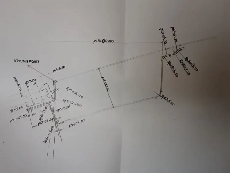
Master section for Front roof rail
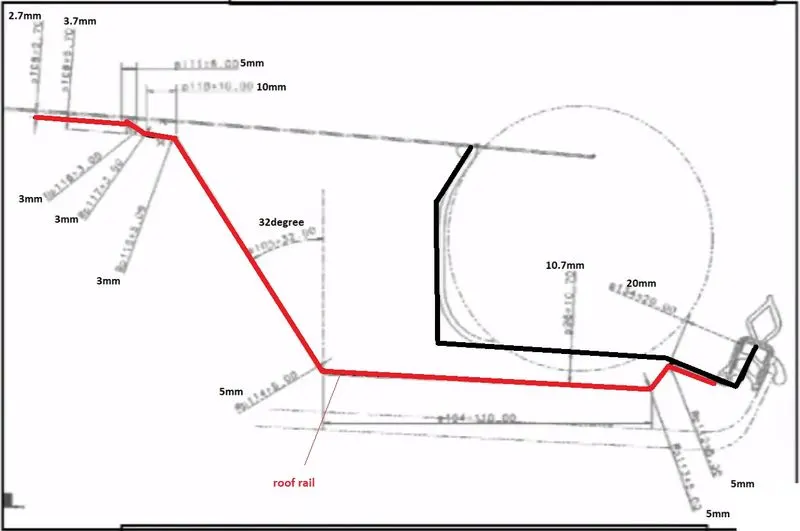
Master section for Rear roof rail
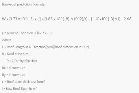
Also, we are provided with the formulas for heat distortion and snow load criteria.
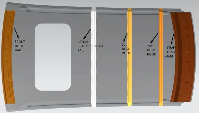
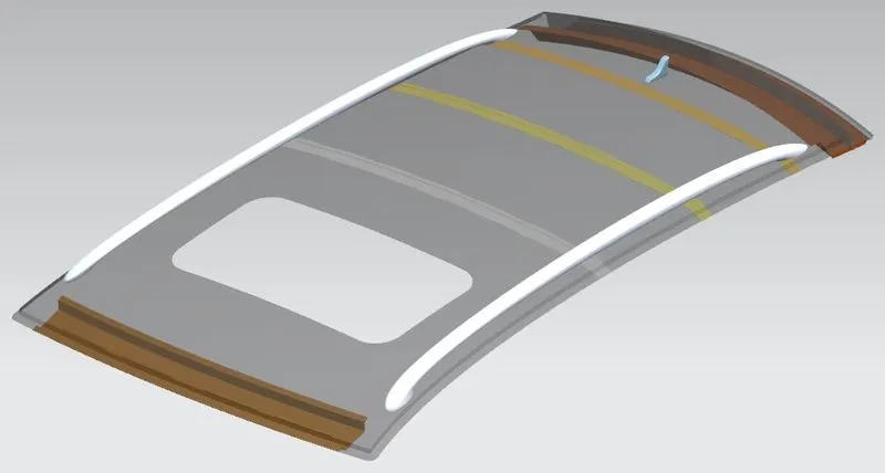
Before explaining the procedure, we will see the final outcome first, so that we get an idea about the positions where we create eveything.
PROCEDURE :
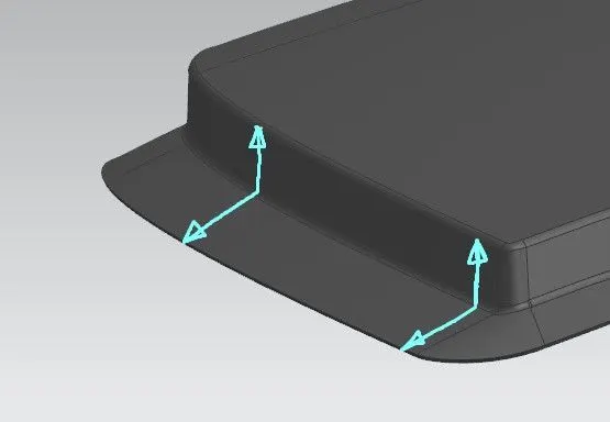
We will start by extracting the surface from the dumb body. From the roof styling, we will add flanges that will have the required space for the rubber film and top edge of front windshield.
Following this, we will create the front roof rail by offsetting the extracted surface. All the offset distances and angles we will consider what we have in the provided master section. The section is given such, that the headroom inside the cabin is adequate plus the viewing angle for the driver is proper and it would not create any hinderance.
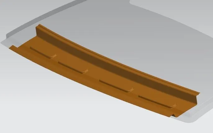
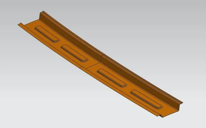
Embosses are given in addition for the better strength of the particular larger flange.
After this, the side ditch area is created simply by adding flanges to the roof styling line and a joined with the front one. This process includes features like bridge curve and studio surface and a uniformly transitted surface is created. This ditch area majorly is utilized for the joining of rails and reinforcements by welding.
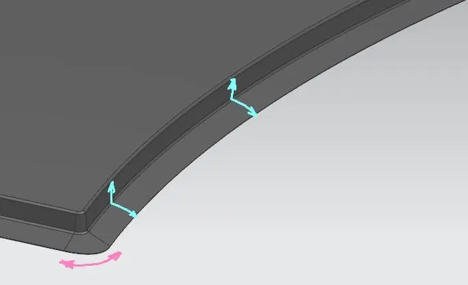
The next step is for the rear ditch area. It is mainly for two types - one has the hinged part of backdoor beneath the outer roof surface and other has the same outside the roof area. Here, we will design for the hinged part outside the roof area.
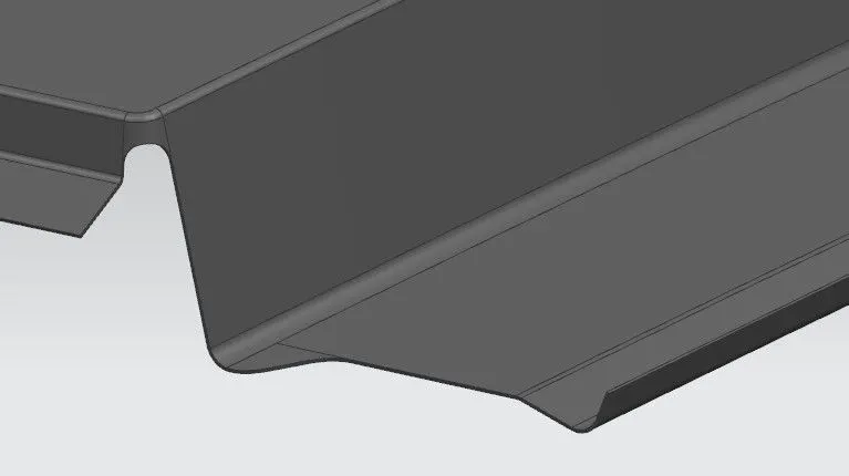
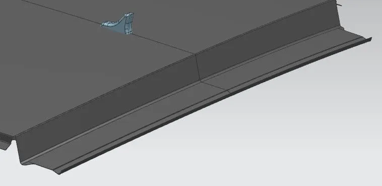
Beneath this, now will create the rear roof rail same way as we created front one. We will follow the master section provided, which is already subjected to the proper visibility and headroom.
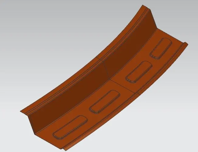
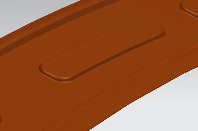
Now, we will design the central reinforcement that will go across the roof length. Features like surface offset, curve offset in surface, trim sheet, studio surface and face blend are used to create the main body of the rail. Then the surface with appropriate width is trimmed that joins the side ditch area. The main body and this part is then joined by studio surface with bridge curves serving as guiding curves and a smooth transitted surface is created. Similarly, 1st bow-roof and 2nd bow-roof are designed same way.
The main aim of providing these rails is to make the roof structurally strong and that can withstand the load from outside factors. The analysis for the same we will see later.
Central reinforcement rail :
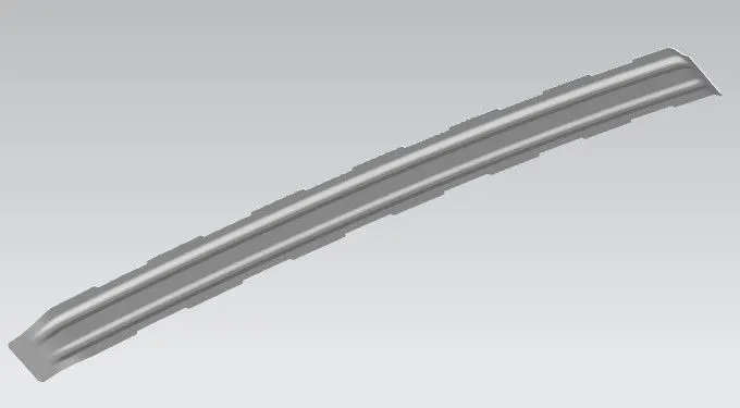
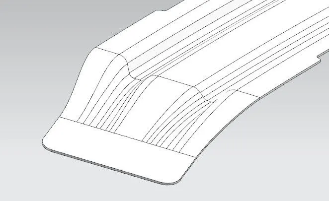
1st Bow roof :
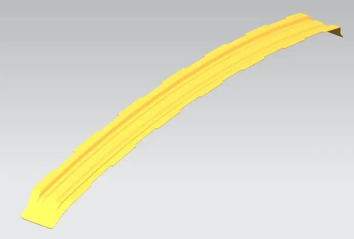
2nd Bow roof :
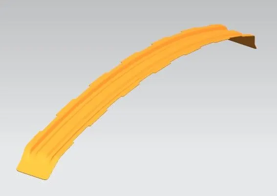
The mastic points and welding points are shown below. Black are the mastic points and purple are the welding spots. These gives the proper joining of the rails with the outer roof surface.
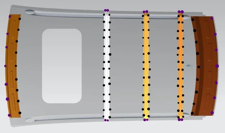
The Final Assembly of the entire roof is like shown
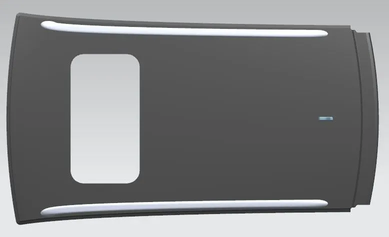
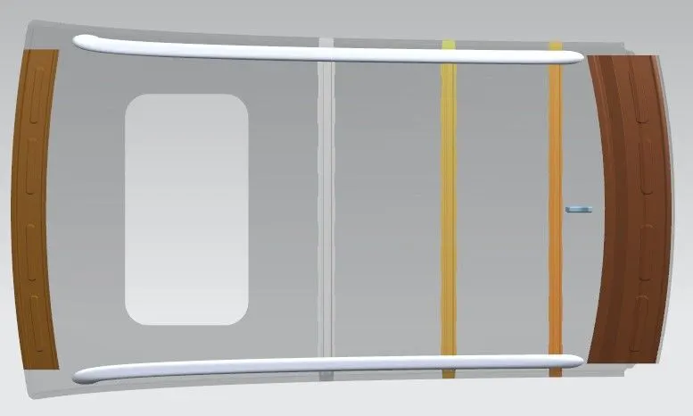
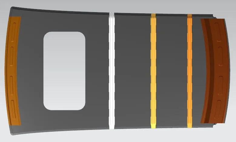
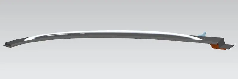
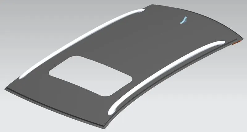
The cross-section of all the rails is taken across the roof length and the section inertia of all is calculated.
Front roof rail
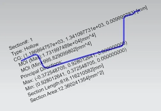
Rear roof rail
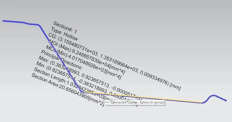
Central Reinforcement
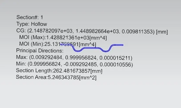
1st bow-roof
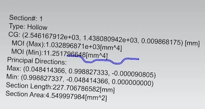
2nd bow-roof
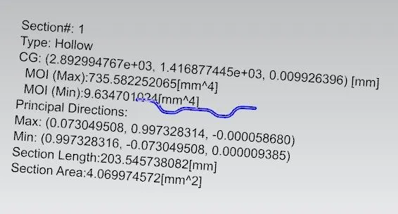
Now we will do Curvature Study of the roof, which will show if the positions of the bow roofs and reinforcemnet is correct or not. From this we will also understand if the curvature will withstand the load or not. Two methods are there for the curvature study.
- Heat Distortion Curvature Study : This study is actually carried out to check the ability of the roof to withstand high tempertures with respect to the positions of rails and bow roofs that increases the strength and stability of the roof.
The Bow–roof prediction Formula is given by
W = [1.73 x 10^(-3) x L] + [1.85 x 10^(-8) x (R^2)/t] + [ 1.10x10^(-3) x l] - 2.68
Judgement Condition : OK< 2.7> 3.1
Where
L = Roof Length in X-Direction[mm](Roof dimension in 0-Y)
R = Roof curvature
R = 2(Rx*Ry)/(Rx+Ry)
Rx = X curvature
Ry = Y curvature
t = Roof plate thickness [mm]
l = Bow Roof Span [mm]
To calculate values of Rx and Ry, we will first create a sketch. In this process, a line is drawn across the roof length in the centre and offsetted at 300mm. Then, symmetric offsets of 100mm are created. Also, the span length between the roof rails is divided in half and a line is drawn across the width and offsets of the same are taken on both sides by 100mm. The intersection points of these lines are then projected to the roof surface, using which arcs are created like shown below. Radius of the same are calculated next.
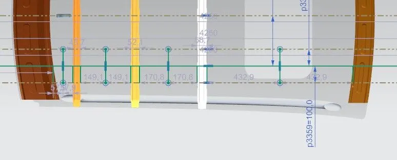
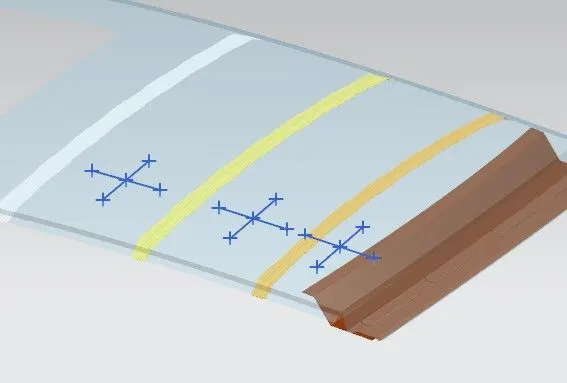

- Snow Load Criteria : This study is carried out to check the stability of the roof against the load of snowfall and the roof sheet should bounce back once the load has been removed.
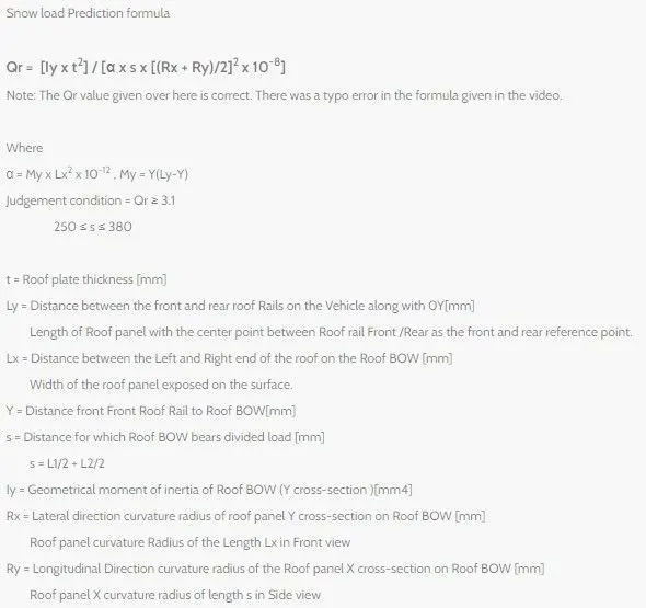
Snow load Prediction formula
Qr = [Iy x t2] / [α x s x [(Rx + Ry)/2]2 x 10-8]
Where
α = My x Lx2 x 10-12 , My = Y(Ly-Y)
Judgement condition = Qr ≥ 3.1
250 ≤ s ≤ 380
t = Roof plate thickness [mm]
Ly = Distance between the front and rear roof Rails on the Vehicle along with 0Y[mm]
Length of Roof panel with the center point between Roof rail Front /Rear as the front and rear reference point.
Lx = Distance between the Left and Right end of the roof on the Roof BOW [mm]
Width of the roof panel exposed on the surface.
Y = Distance front Front Roof Rail to Roof BOW[mm]
s = Distance for which Roof BOW bears divided load [mm]
s = L1/2 + L2/2
Iy = Geometrical moment of inertia of Roof BOW (Y cross-section )[mm4]
Rx = Lateral direction curvature radius of roof panel Y cross-section on Roof BOW [mm]
Roof panel curvature Radius of the Length Lx in Front view
Ry = Longitudinal Direction curvature radius of the Roof panel X cross-section on Roof BOW [mm]
Roof panel X curvature radius of length s in Side view
To calculate values of Rx and Ry, we will first create a sketch. In this process, a line is drawn across the roof length in the centre and offsetted at 100mm on both sides. Also, the span length between the roof rails is divided in half and a line is drawn across the width and offsets of the same are taken on both sides by 100mm. The intersection points of these lines are then projected to the roof surface, using which arcs are created like shown below. Radius of the same are calculated next.
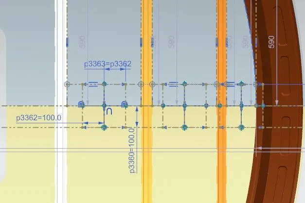
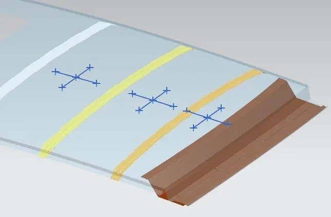

We can see from the tables, that for the available curvature, our positions of reinforcement and bow-roofs are correct. And so can proceed with the same positions. If there be any wrong output, we can solve by repositioning the bow-roofs or can change the curvature of the roof and get correct values.
At last, we will do the Draft Analysis for all the parts.
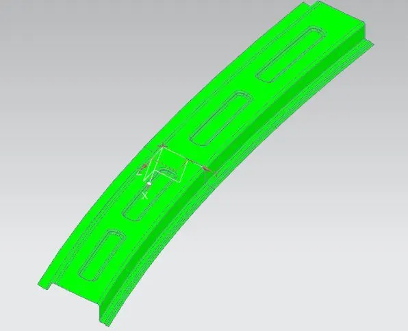
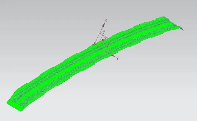
Sheet metal parts are generated from a press tool or some forming tools, all such kind of tools require some space when after forming they come back to their initial zero point location. If we dont provide a draft angle, then the tool will not be able to come out easily and the movement will destroy the generated surface or reduce the finish. 3 degrees is a minimum value for sheet metal. Here we will analyze for 5 degrees.
Front roof rail
Central reinforcement
First bow-roof
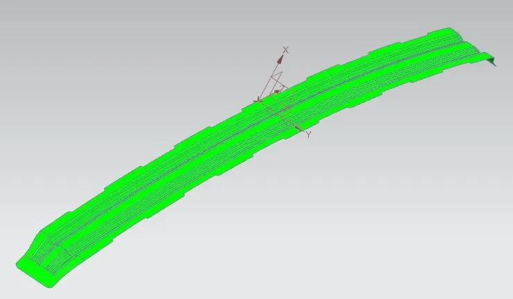
Seconf bow-roof
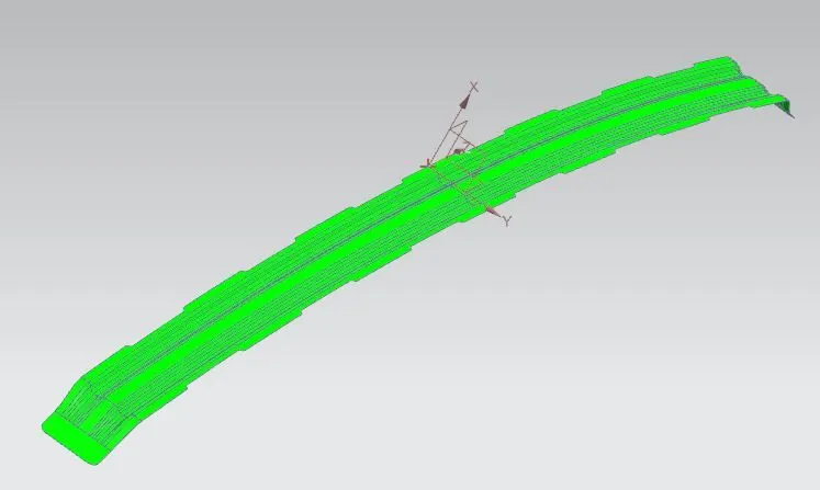
Rear roof rail
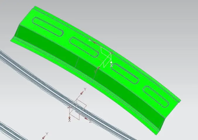
We can see that all the parts have turned green and can see no other colour showing negative draft. Therefore, all the designs are correct and can proceed them further to the CAE team or for manufacturing.
CONCLUSION :
- All the parts are designed from the provided dumb body roof part and master sections.
- Did curvature study and analysed the stability of roof for heat distortion and snow load criteria and found OK.
- Did draft analysis and checked section inertia and found feasible and OK.
- Can proceed further to the CAE team for futher analysis.