Wiring harness design in CATIA V5 - 3D modeling Week 5 & 6 Challenge
Wiring harness Bundle - Week 5 & 6 Challenge
As inputs, we are provided with connectors list and two layouts, according to which we will create a Wiring Harness Layout. First of all, download the CAD files of all the needed connectors and define them electrically. Now, follow the steps to create a harness layout :
- Start a new product file and rename it as an assembly context file.
As we know, a main assembly file will have geometrical bundle and virtual environment in it.
- Click on 'Add Product'
 and rename it as an assembly or Harness A.
 - We can define the Mechanical assembly as a Geometrical Bundle by switching to Electrical Harness Assemble and clicking on 'Geometrical Bundle'
 and selecting the product file from feature tree.
The layout provided to us is shown below.
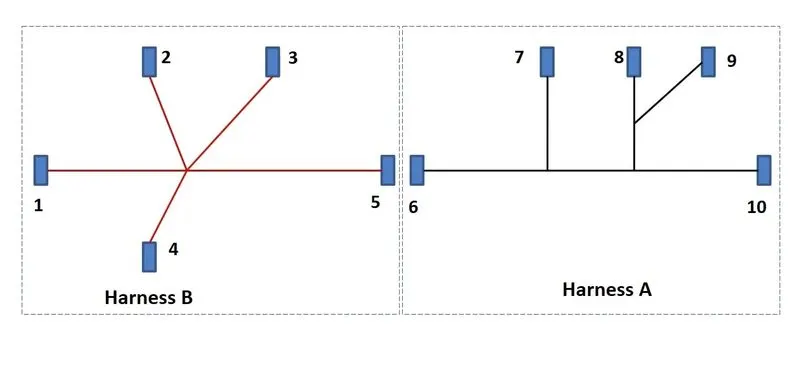
- Next step is to add existing components in Geometrical Bundle. Click on 'Add Existing part'
 and add all the connecors that are defined electrically before.
 - Being in Mechanical Assembly Design, re-orient all the connectors according to the layout.
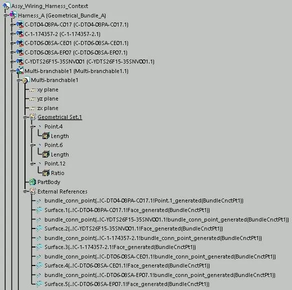
- After attaining the layout by positioning the connectors at their positions, now switch to Electrical Harness Assembly and create a Multi-branchable.
- Click on 'Multi-Branchable Document'
 and add branchables according to layout.
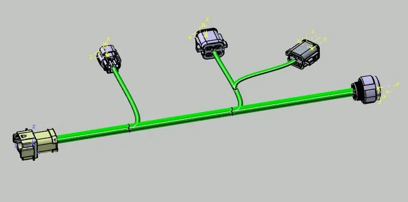
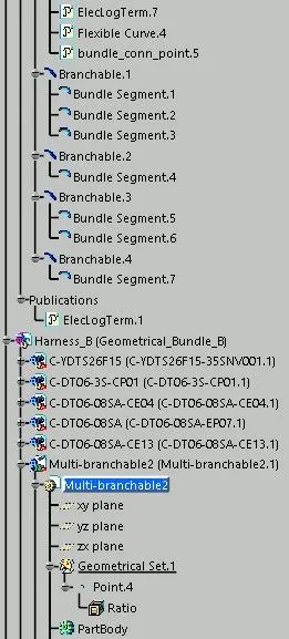
Similarly, add another product file as Harness B and follow the same steps to create another wiring harness layout.
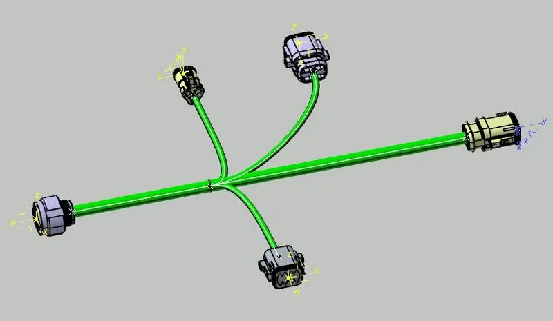
Align both the assemblies as shown, in such a way that male and female counterparts of connector come closer.
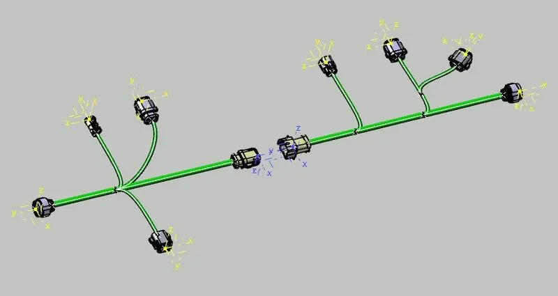
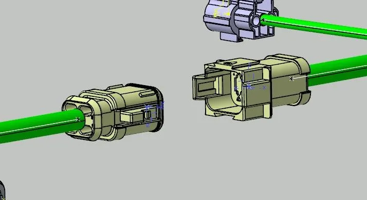
Switch to Electrical Assembly Design worbench and click on 'Add Electricals'  and then select both the connectors for an interconnection. It is visible how perfectly both the assemblies are now joined.
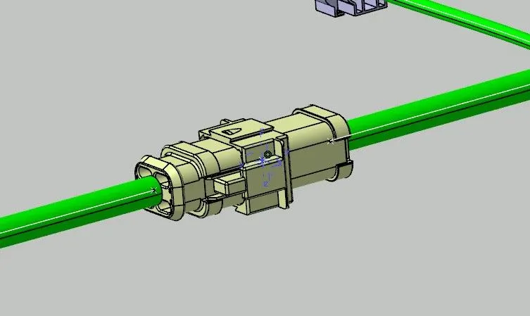
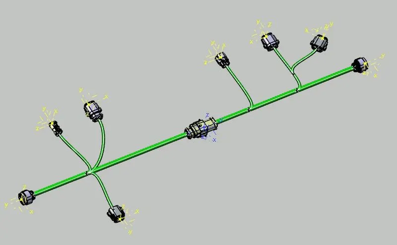
Now, after assembling both together, we will check for its connectivity.
- Go to Edit>Search or directly press Ctrl+F and a window is visble.
- Select options as shown from drop-down menus and for 'Attribute Criterion', select False.
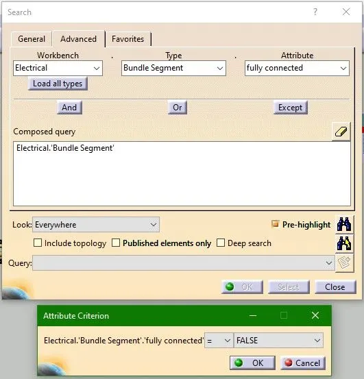
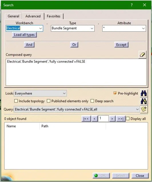
- Click OK and click on Search button
 and objects found are none. That means there is no such bundle segment which has no connection.
- Now try for the True Attribute Criterion and number of segments found are 12, which is also the total number of bundle segments that the assembly has. That means all the segments are fully connected.
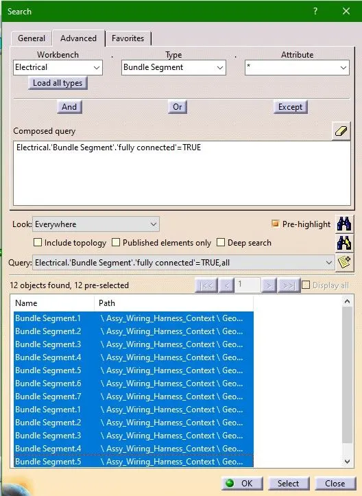
- Click on Search Select
 and we can see all the bundle segments highlighted.
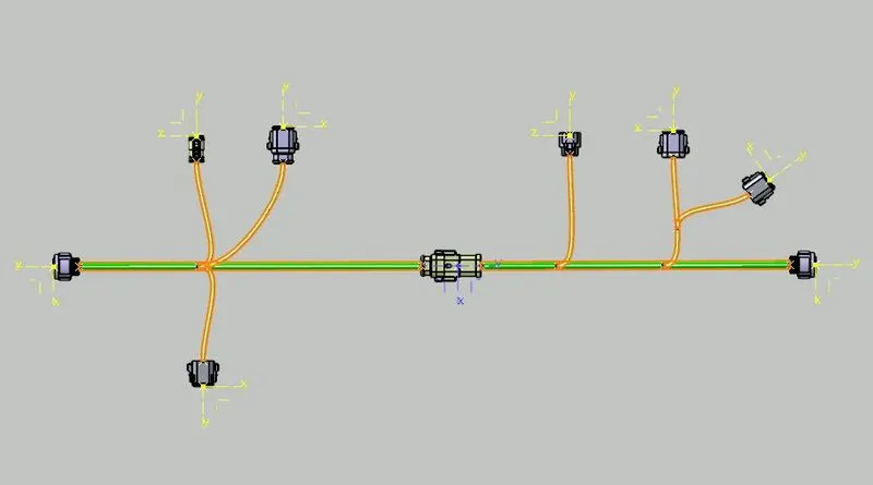
Now, adding 3D Annotations is just a two-step process. For this switch to Mechanical Assembly Design workbench and
- Click on plane
 in Annotation toolbar and select the plane in which the text is needed. Like here we select the face of connector.
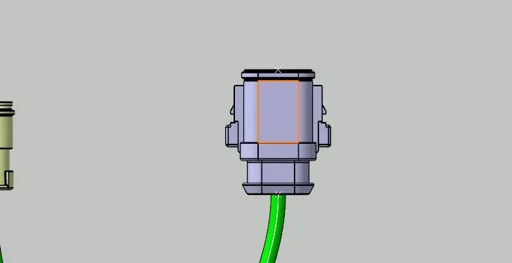
- Click on type of annotation needed
 and type the text and change the properties of it as required.
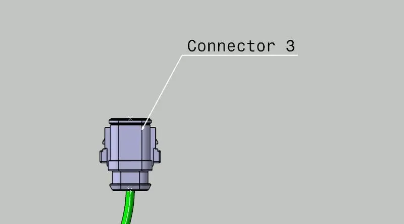
Similarly name all the connectors and also the harnesses.
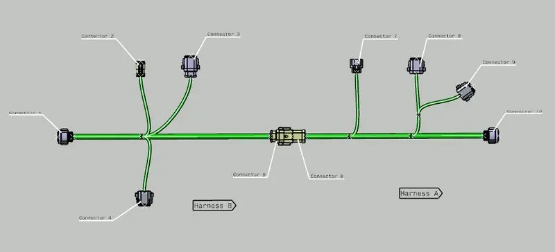
The entire assembly would look something as shown below.
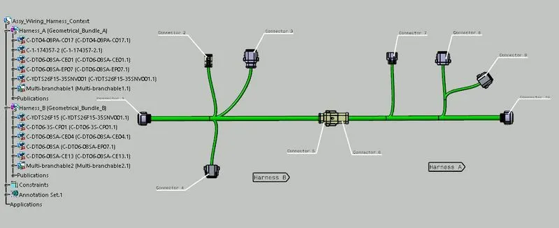
Next step is to convert this product (assembly) into CATPart. This is done to make the product readable by any person in any software. So for that we will later save it as .igs or .step format.
- Switch to Mechanical Assembly Design workbench and go to Tools>Generate CATPart from Product.
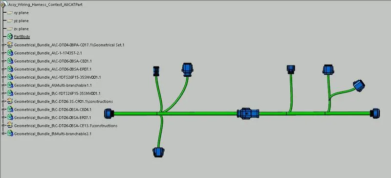
Also there are no bundle warning signs in Feature Tree.
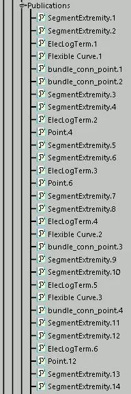
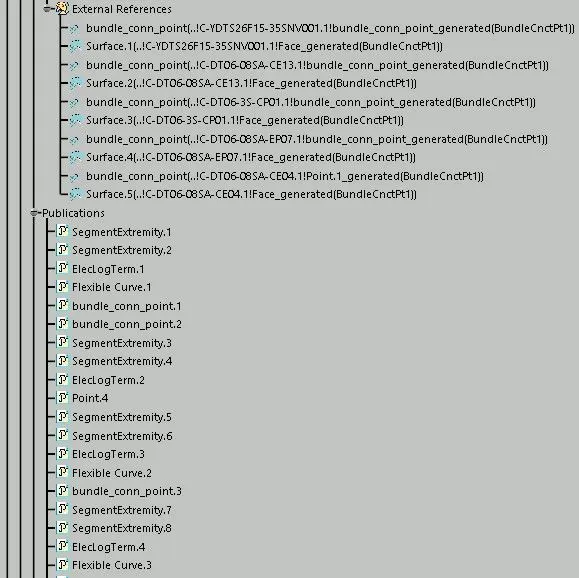
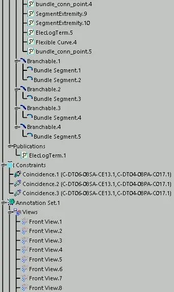
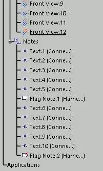
Tree Structure