Wiring harness design in CATIA V5 - 3D modeling Week 4 Challenge
Wiring Harness Layout - Week 4 Challenge
As inputs, we are provided with connectors list and a layout, according to which we will create a Wiring Harness Layout. First of all, download the CAD files of all the needed connectors from open source and define them electrically. Now, follow the steps to create a harness layout :
- Start a new product file and rename it as an assembly context file.

As we know, a main assembly file will have geometrical bundle and virtual environment in it.
- So click on 'Add Product'
 and rename it as an assembly or as shown.
 - We can define the Mechanical assembly as a Geometrical Bundle by switching to Electrical Harness Assemble and clicking on 'Geometrical Bundle'
 and selecting the product file from feature tree.
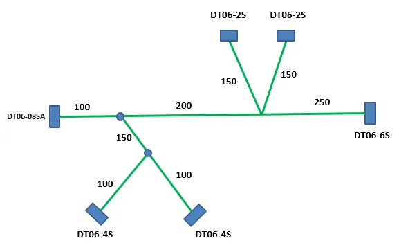
The layout provided to us is shown below. To create the exact same layout, it is needed to create a sketch.
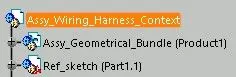
- Add a part file by clicking on 'Add Part'
 and rename as reference sketch.
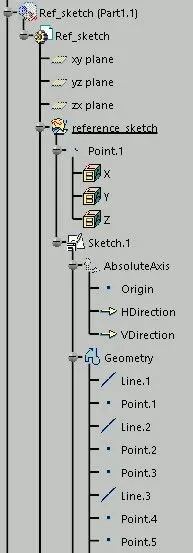
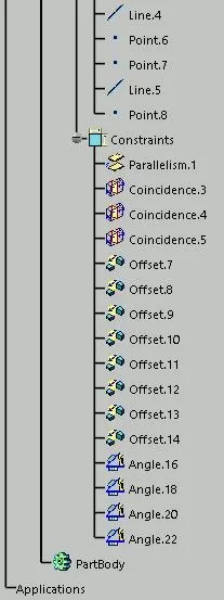
- Define the part file and create a sketch in it as shown below. It should exactly resemble the layout required.
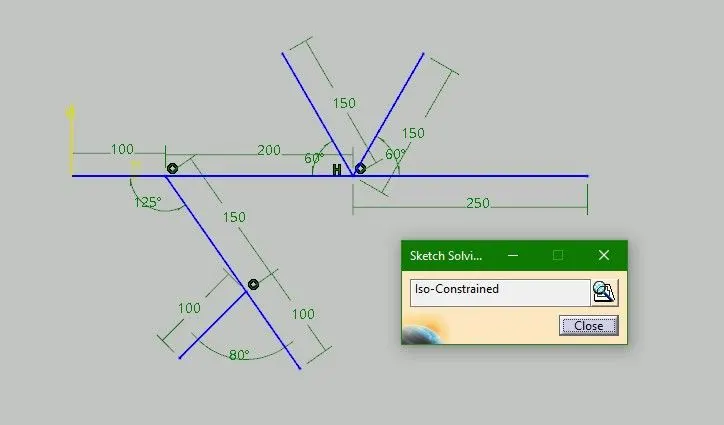
- We can use these end points to position the connectors.

- Next step is to add existing components in Geometrical Bundle. Click on 'Add Existing part'
 and add all the connecors that are defined electrically before.
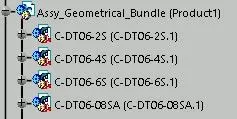
- Being in Mechanical Assembly Design, re-orient all the connectors and connect the bundle entry points with the sketch end-points by snapping.
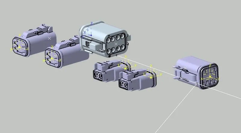
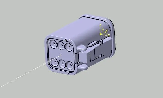
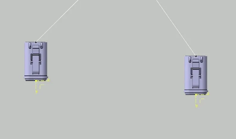
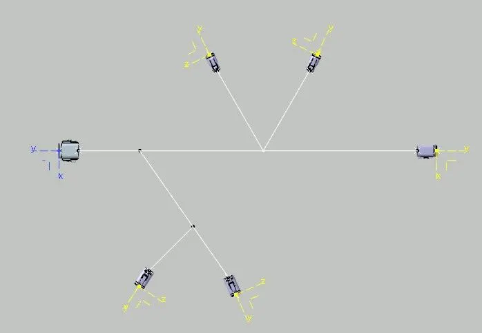
After attaning the layout by positioning the connectors at their positions, now switch to Electrical Harness Assembly and create a Multi-branchable.
- Click on 'Multi-Branchable Document'
 and a window will open.
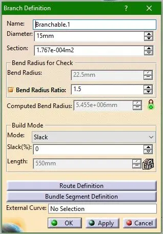
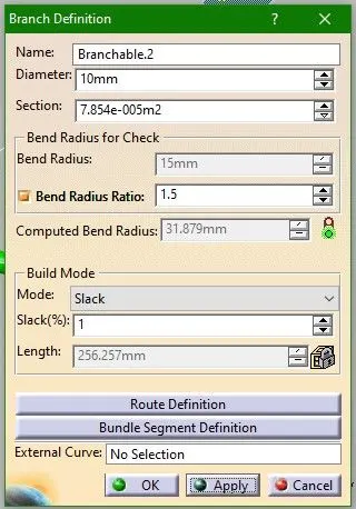
 - Put value of bundle diameter, bend radius ratio (that is normally 1.4-1.5), % of slack if needed and click on 'Route Definition'.
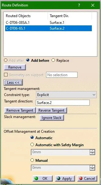
- As routing objects select the connector for which the routing is required. For main bundle here, select two extreme end connectors.
- Tangent and offset management will work automatically.
- Click OK.
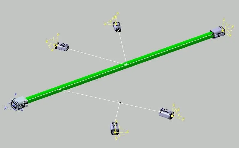
This will craete a branchable between two connectors as shown.
Now, we want to create another branchable as red line show in picture and a starting point from main bundle.
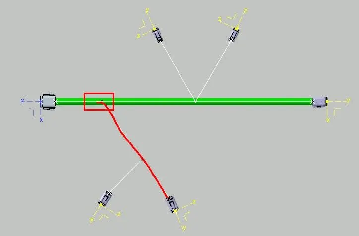
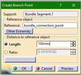
- Select on 'Add Branch Point'
 and a window will pop up.
 - Click on the harness branch where a starting point is needed and provide distance or ratio value and hit OK.
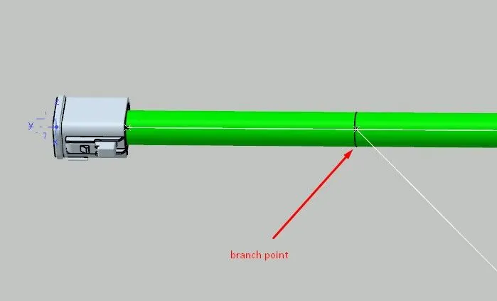
- Create another branch by clicking on 'Multi-Branchhable Document' as before and fill the values.
- Here we are giving 1% slack. Slack is nothing but the looseness in bundle segment.
- As a routing object, select a bundle segment in first place and then the connector and click OK.
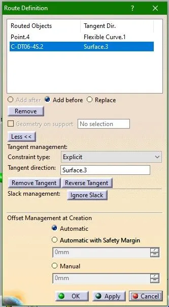
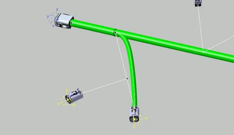
Similarly create branch points and add branchables for all connectors. Finally, a wiring harness layout is created as required.
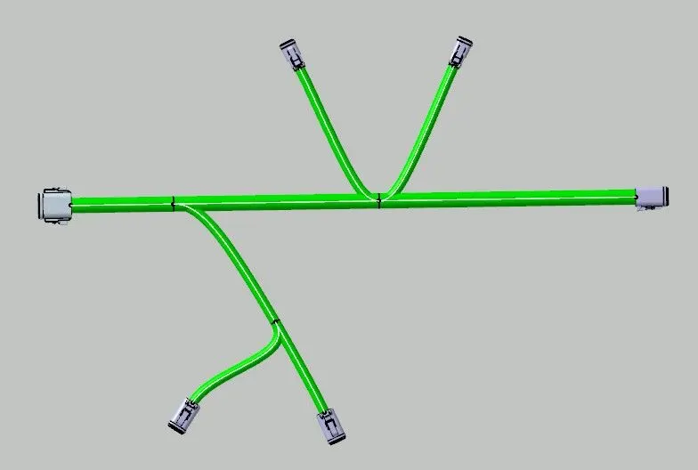
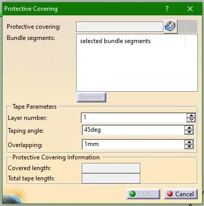
- Now, lets add some protective layers to bundles. Click on 'Protective Covering'
 and a window will open.
 - Select the bundle segment needed to be covered.
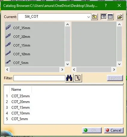
- Click on the library icon visible and select a Protective component from catalog.
- Select a Cot tube with inner diameter greater than the bundle diameter and hit OK.
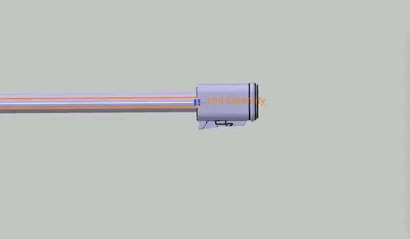
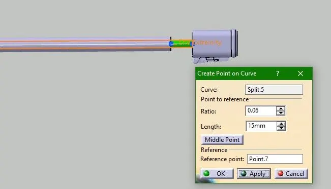
- It is visible that a bundle segment is covered with protective layer, but it cannot touch the connector. So, click on Extrimit point and give some distance or ratio value.
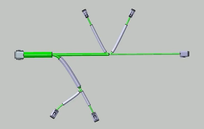
- A fully created Wiring Harness Bundle will be something as shown below.
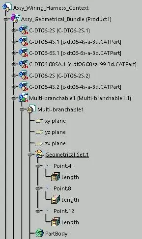
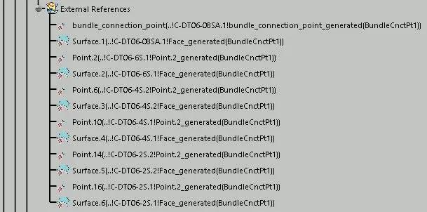
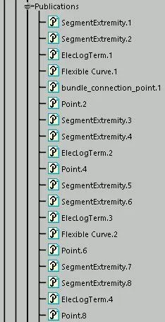
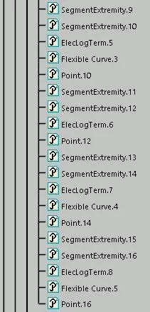
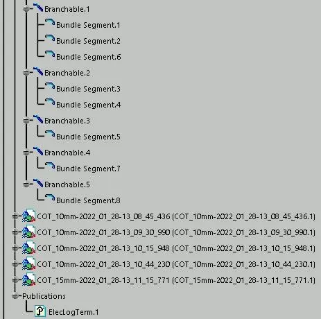
Tree Structure