Week 8 - Challenge 2 - Base Bracket Design
BASE BRACKET DESIGN
AIM : The objective here is to create a base bracket plastic component from given Class A surface.
The approach here will be simple. First we will create a tooling axis for the given Class A surface. Later we will generate Class B & C surfaces and by using a closed surface, will create a solid plastic component and validate it by doing Draft Analysis.
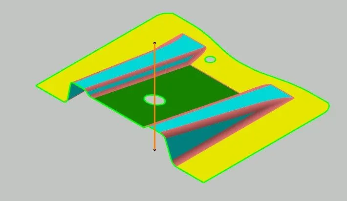
The provided Class A surface is shown below.
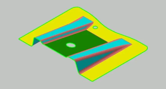
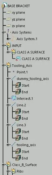
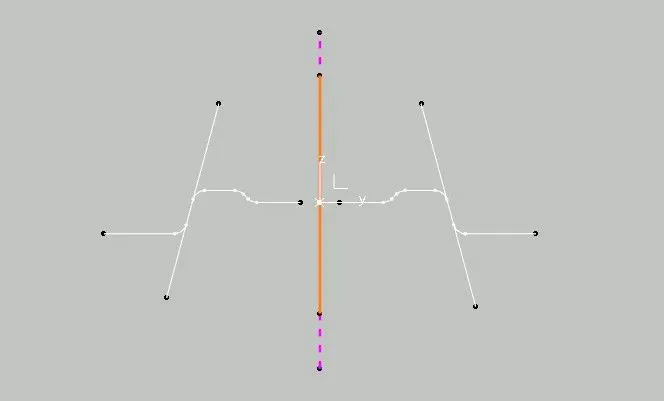
By examining it, we can see it is kind of symmetric and has a big hole in centre. So, create a point at that hole's centre and add an axis system there. Draw a line passing through that point in vertical direction along Z-axis, which will be the dummy tooling axis.
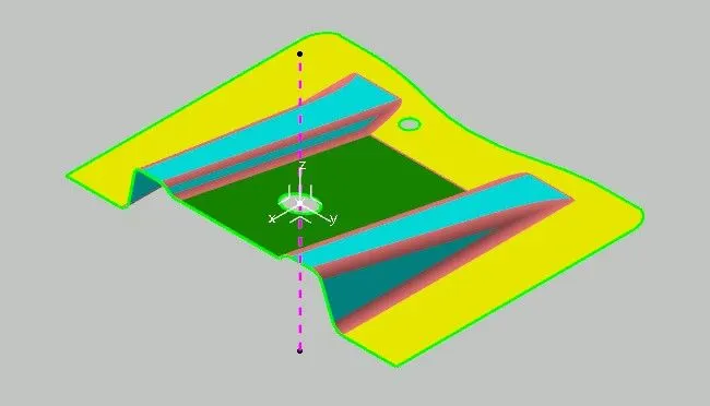
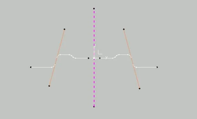
As we can see, the walls in Y-direction can only create some problem in ejection of the component. So, we use bisection method and take an intersection of this entire surface with YZ plane.
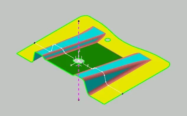
Create lines along those walls intersections and also bisect them further. This will give the Tooling axis.
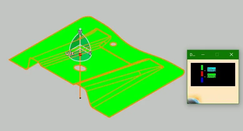
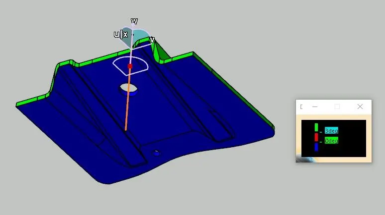
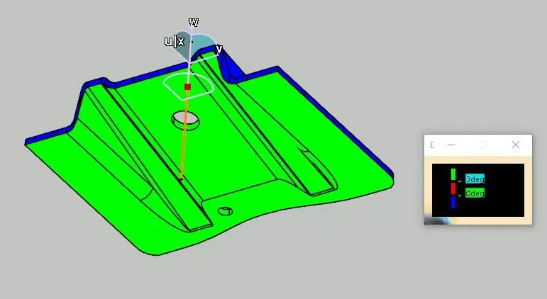
Now, using draft analysis, lets check whether the created tooling axis is correct or not. For this, hold and drag the ....... along the tooling axis and as we want minimum draft angle to be 3 degrees, set 3 derees in the colour code. We can see the entire surface turned green, that means the toolin axis is correct.
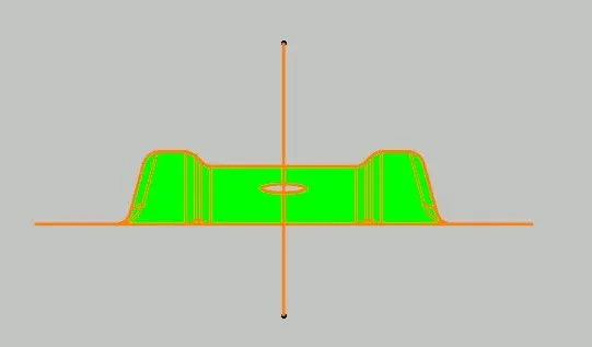
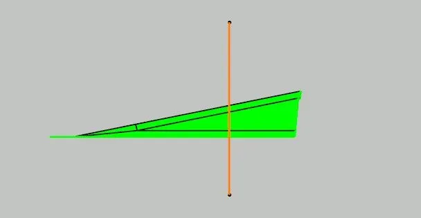
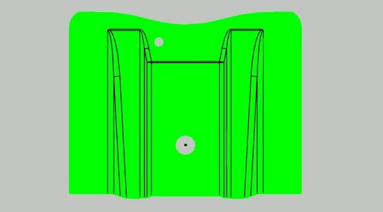
Now, the tooling axis is created, lets go further for Class B surface. Class B surface is actually a surface on the other side of the thickened component, or can say the hidden surface or the surface to which other engineering features are connected. Lets divide this Class A surface into two parts: ribs and base. First we will extract the walls of both the ribs.
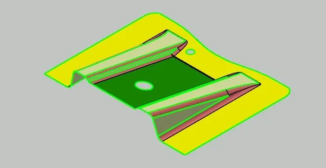
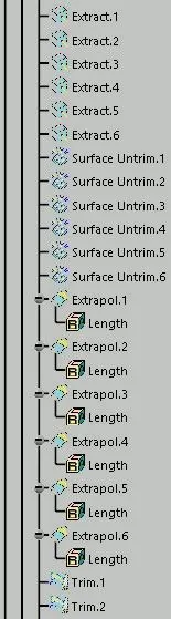
After extracting the walls, the uneven shape needs to be uniform. So, untrim all the surfaces and extrapolate them by some length. Make sure to extrapolate with curvature continuity.
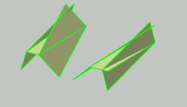
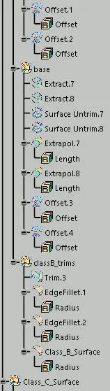
Trim these surfaces, keeping the Class A surface shape in mind. Later offset them, by the desired thickness value (here we are taking 2.5mm). And as the class B surface will come inside, direction of offsetting will be downwards.
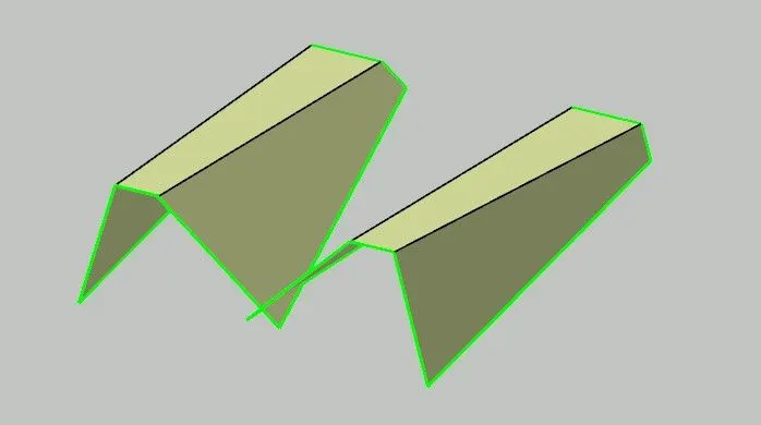
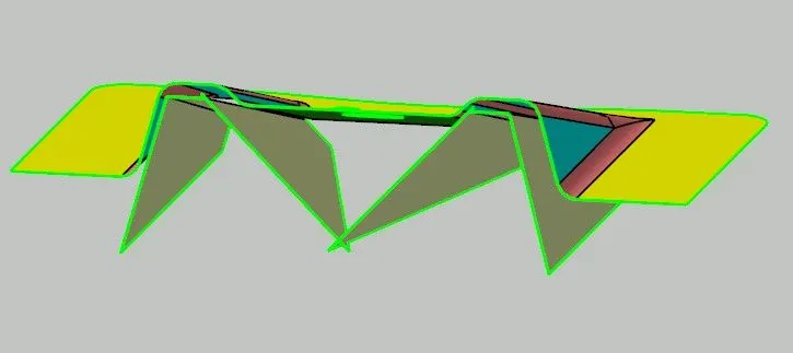
Same way, extract, untrim, extrapolate and offset the remaining base surfaces as shown in figure in blue and sky blue colour.
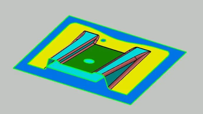
Trim all the generated surfaces in the form of Class A surface and add edge fillets.
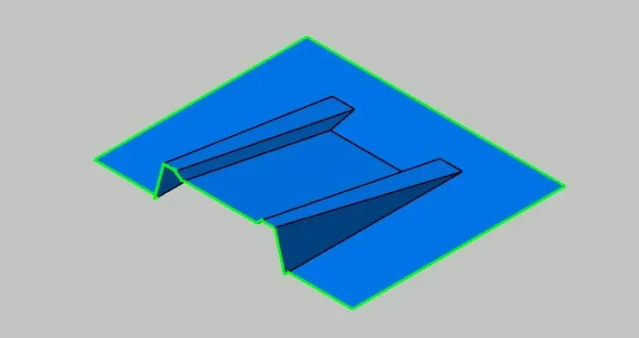
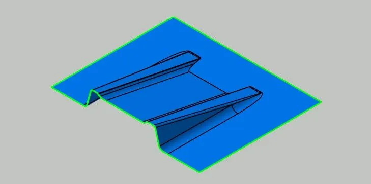
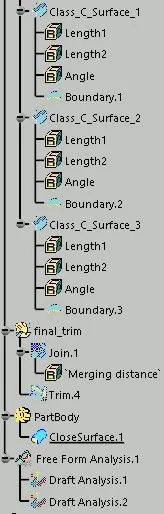
To create Class C surface, the surface which will act as walls here and enclose the entire component, select the open boundaries of Class A surface and sweep those edges towards Class B surface with some draft value. Here, we have to maintain a minimum draft of 3 degrees, so 4 degrees draft value for this surface is taken.
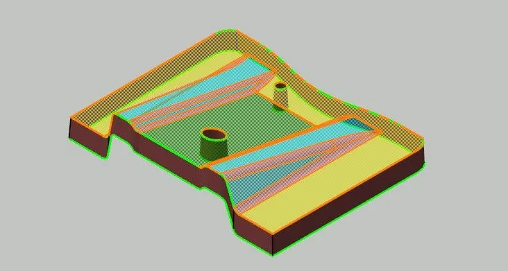
NOTE : While selecting the direction of Class C surface generation, keep in mind the concept of parting surface. The parting surface should never be along the Class A surface, as there are chances of flash generation which can reduce the aesthetics. So, here we will select outward direction, so that the Class C surface gets the clearance with Class A itself.
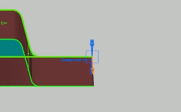
After this join both the Class A and C together and trim with Class B. This will give an enclosed surface structure (shown in pink).
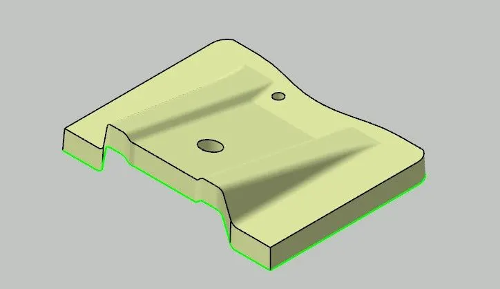
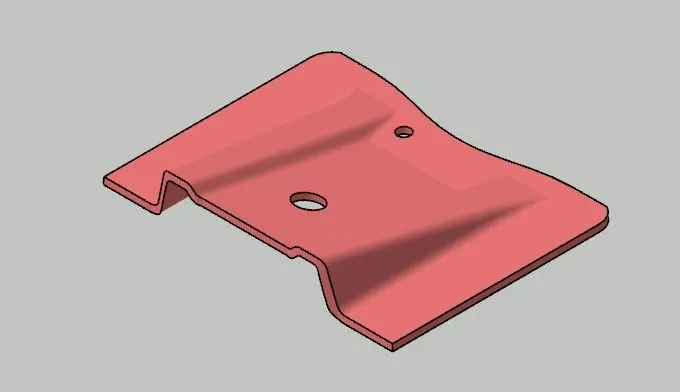
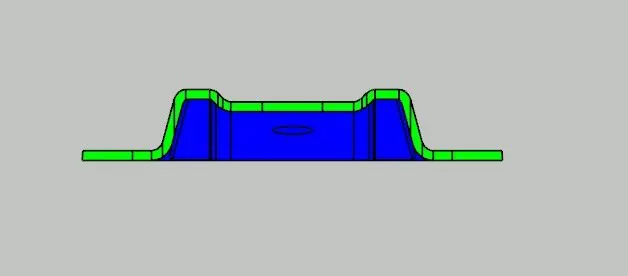
Switch to part workbench and craete a solid out of it. And the produced part is a bass bracket plastic component.
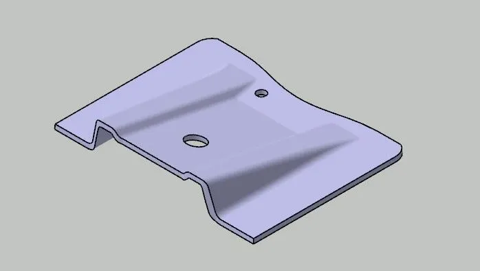
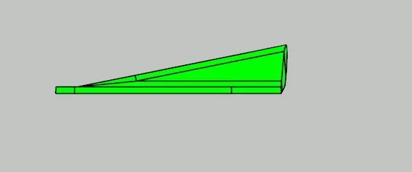
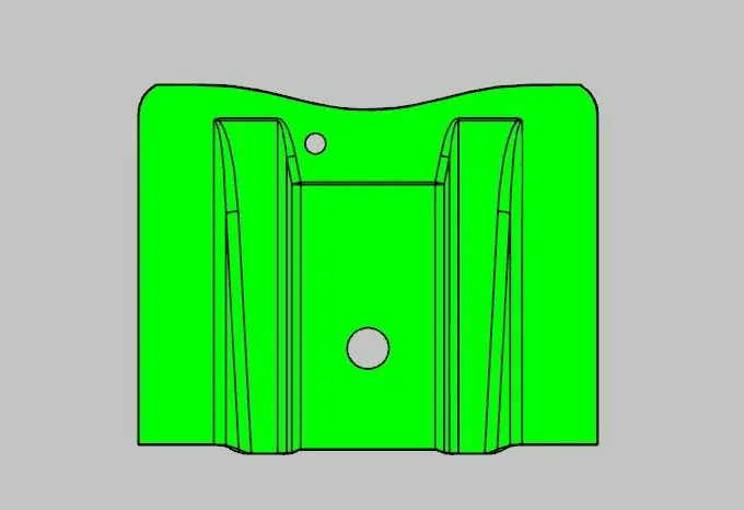
Validate the component by doing draft analysis. All green shows the clearance will be perfect.
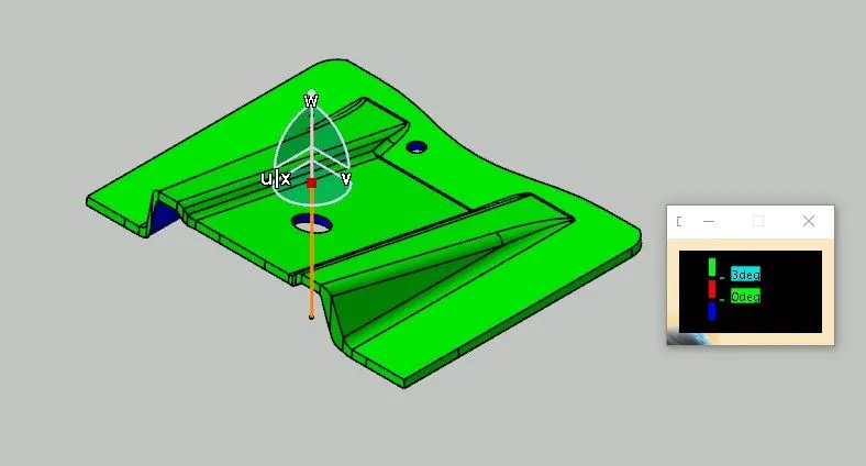
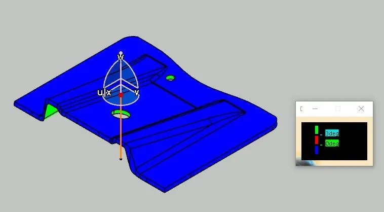
Check the clearance for other side by inversing the axis.
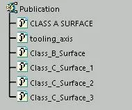
Tree Structure