Hood design-Week 2
CAR HOOD DESIGN
OBJECTIVE : The aim is to design components of the hood/bonnet of a car and assemble them together.
INTRODUCTION : This project will make you understand about the hood of a car, explain some sheet metal operations that are commonly used in designing and take you to the step by step procedure of designing hood components like its inner panel, outer panel, reinforcements and setting the trajectory of striker. Designing of the model is carried out in Siemens NX-12 here.
HOOD : The hood (North American English) or bonnet (Commonwealth English) is the hinged cover over the engine of motor vehicles. Hoods can open to allow access to the engine compartment, or trunk on rear-engine and some mid-engine vehicles for maintenance and repair.

On front-engined cars, the hood may be hinged at either the front or the rear edge, or in earlier models, it may be split into two sections, one each side, each hinged along the centre line. Hoods are typically made out of the same material as the rest of the body work. This may include steel, aluminium, fiberglass or carbon fiber. However, some aftermarket companies produce replacements for steel hoods in fiberglass or carbon fiber to make the vehicle lighter.
Hood is typically supported by rods or some fixtures, so that it stays at a position and a person can lean onto it hassle free and work. These includes
Support Rod : A hood rod is designed to hold your hood propped open whenever you need to do some work in your car's engine bay. When used, it must be firmly secured to ensure that it provides a stable hold on the hood. Meanwhile, when not in use, it must be kept stable in place and must not move around. The hood rod clip is the part assigned with that function. This clip clamps onto the rod and ensures that it is firm in its place when not in use. It keeps the rod from moving around under the hood and from causing trouble.
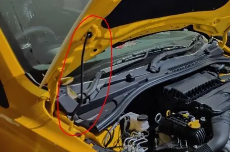
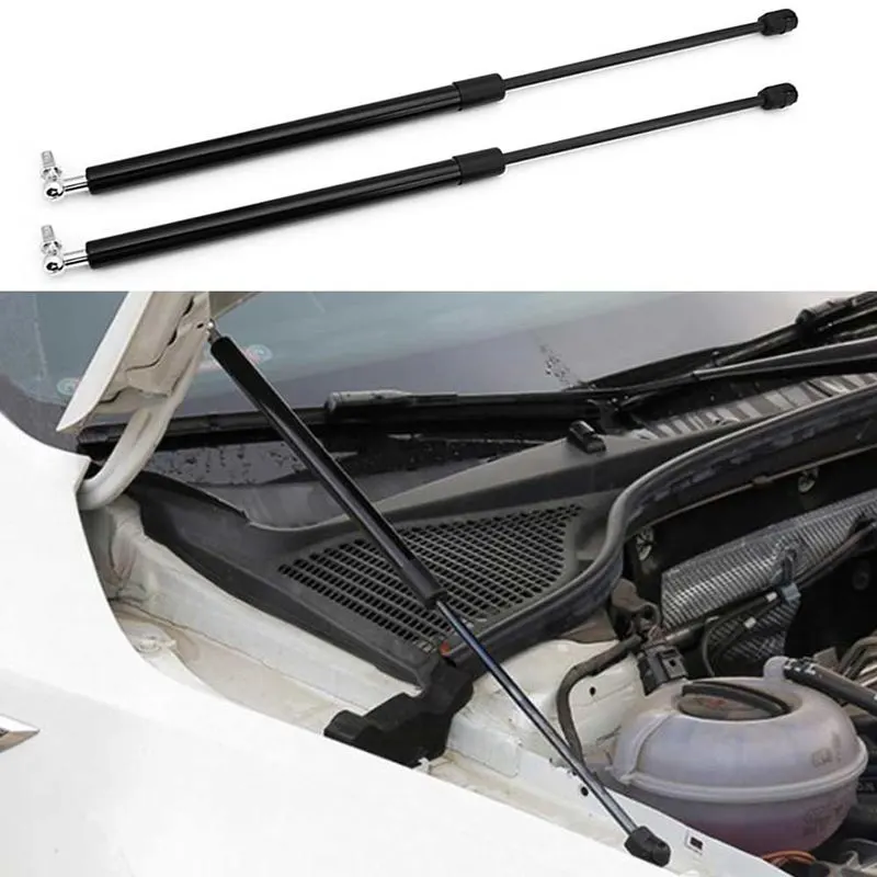
Gas Stay : This is used to open the car hood by just providing little lift force. A small effort is all it needs and other work is done by gas pressure. It is normlly found in high-end cars where the mass of hood is more than normal.
Sheet Metal Operations :
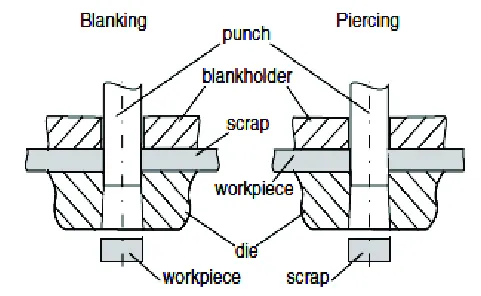
- Blanking & Piercing : Blanking and piercing are shearing processes in which a punch and die are used to produce parts from coil or sheet stock. Blanking produces the outside features of the component, while piercing produces internal holes or shapes. The web is created after multiple components have been produced and is considered scrap material. The "slugs" produced by piercing internal features are also considered scrap. The terms "piercing" and "punching" can be used interchangeably.
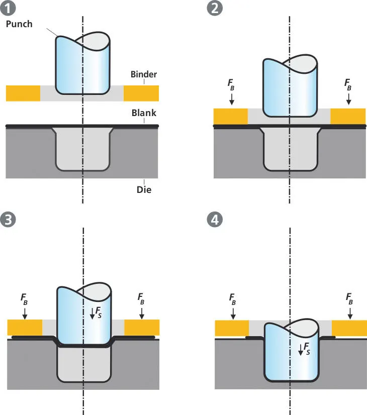
- Deep Drawing : Deep drawing is a sheet metal forming process in which a sheet metal blank is radially drawn into a forming die by the mechanical action of a punch. It is thus a shape transformation process with material retention. The process is considered "deep" drawing when the depth of the drawn part exceeds its diameter.
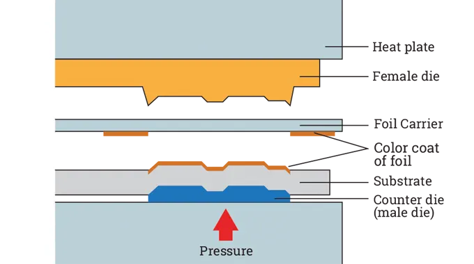
- Embossing : Sheet metal embossing is a stamping process for producing raised or sunken designs or relief in sheet metal. This process can be made by means of matched male and female roller dies, or by passing sheet or a strip of metal between rolls of the desired pattern.
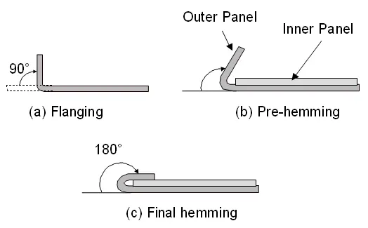
- Hemming : Hemming is a forming operation in which the edges of the sheet are folded or folded over another part in order to achieve a tight fit. Normally hemming operations are used to connect parts together, to improve the appearance of a part and to reinforce part edges.
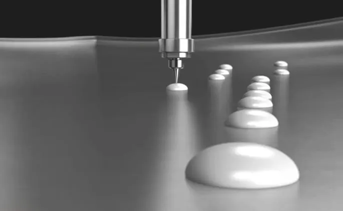
Mastic Points : These are the spots where the inner panel and the outer panel of hood are joined or can say sealed together using a mastic glue. To fix the outer panel, if process like bolting, riveting or welding is used, it will lose all its aesthetics. So, mastic sealant is used which is elastic compound and acts like rubber. It is placed between both the panels. Initially it is in paste form and after hot furnace bath it gets solidify and gives strength to the panels together. One spot normally has influence over diameter of 80 mm.
Parts of a Hood/Bonnet :
- Hood Outer Panel
- Hood Inner Panel
- Hinge Assembly
- Latch & Striker
design approach is carried out in a most effective way and step by step procedure is explained. The master sketch of the panel was already provided on the basis of which, the inner panel is created here.
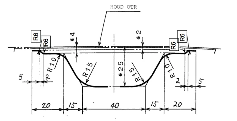
We will design the inner panel first, so lets start with the given data, a body stretched to full dimension of outer panel.
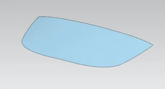
Next trim the sheet into half.
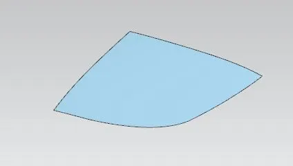
Take a topmost surface offset and keep dimensions according to master section, i.e. 2mm.
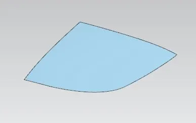
Taking curve offset on surface of 20mm.
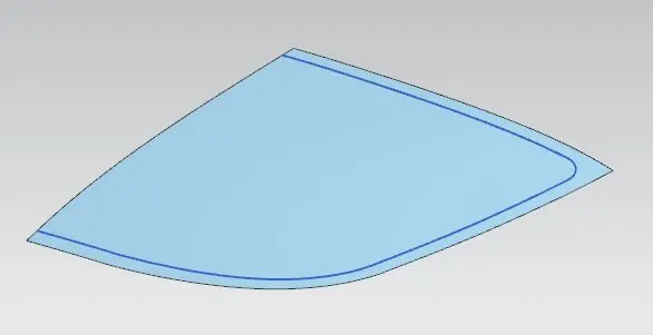
Trim sheet and keep the outer part.
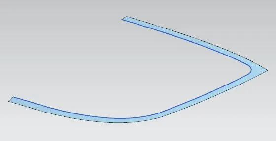
Take another surface offset of 4mm.
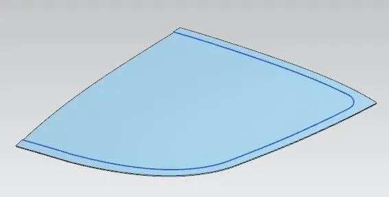
Now offset curve same way for 22mm inside.
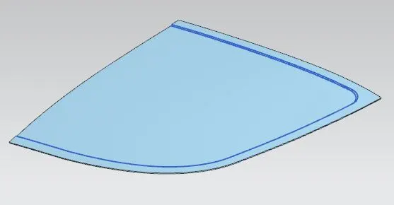
Trim outer part of sheet.
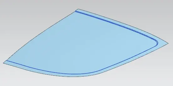
Now we add surface through curve and fill the gap.
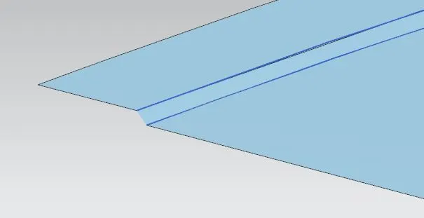
Taking another offset of same surface upto 25mm.
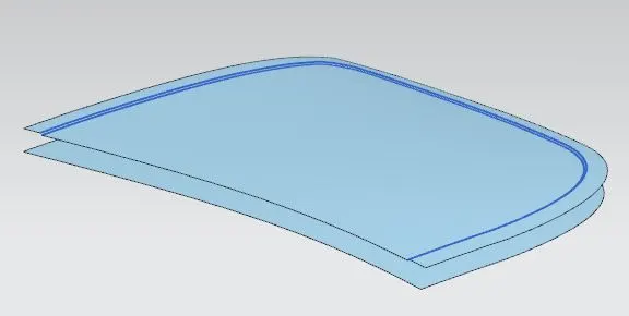
Do curve offset on surface and trim sheet.
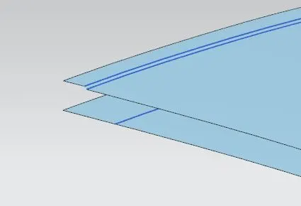
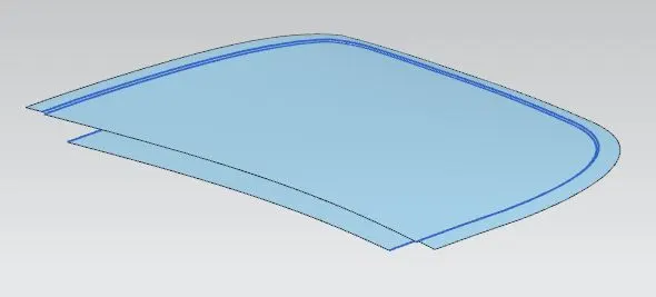
Now to fill gap, we create surface by law extension command and keep draft of 5 degrees outwards.
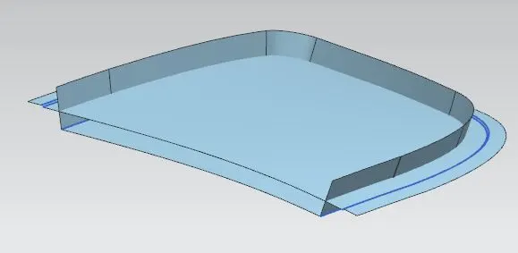
Using trim and extend feature, we eliminate some part and get this structure.
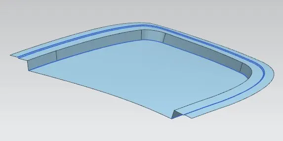
Now we will blend these sharp edges by edge or face blends and keep dimensions as said.
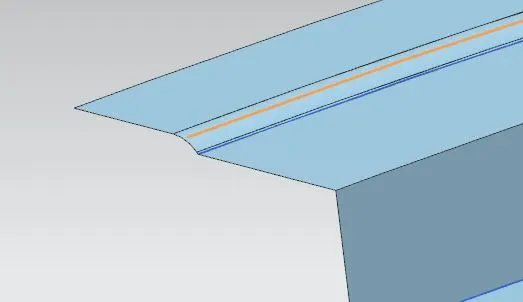
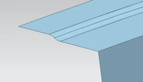
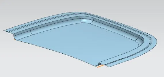
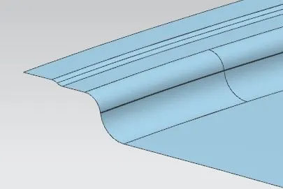
After blending, we will create a sketch and project it to the surface. We keep some space for hinge and striker reinforcement.
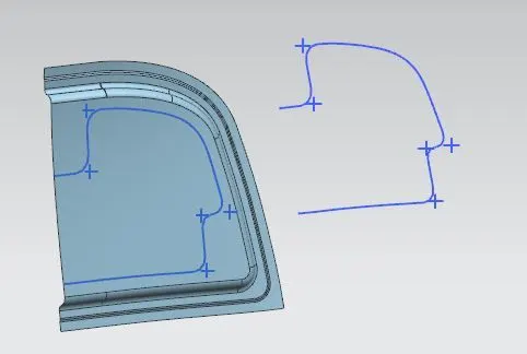
We follow it by Law extension surface, offset the base surface to 5mm upward and apply trim and extend to get an embossed shape for the profile.
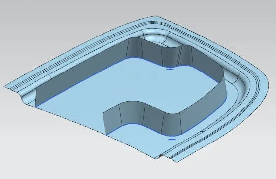
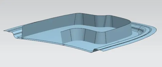
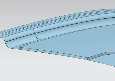
Then trim the unwanted part.
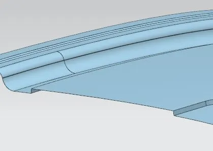
We create one more sketch and project it to the same part. Later, use law extension with draft, surface offset of 5mm, trim and extend and trim sheet to get desired output.
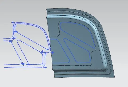
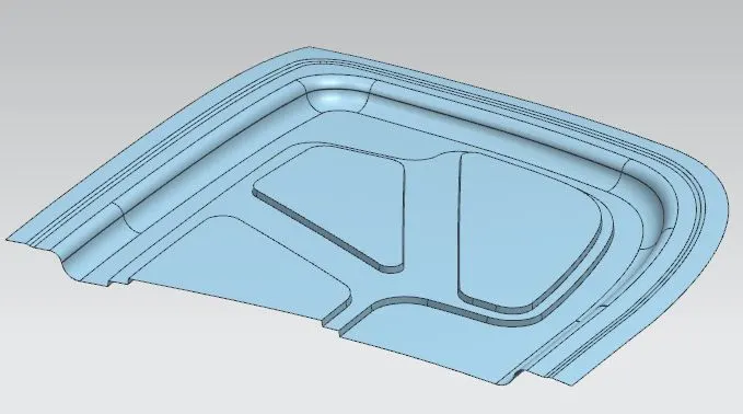
Another sketch we create to remove some material from the workpiece, so we can give some hollowness to the panel for safety reasons. Add spots for mastic points. Then project it in same direction as did before.
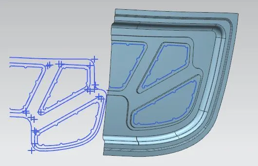
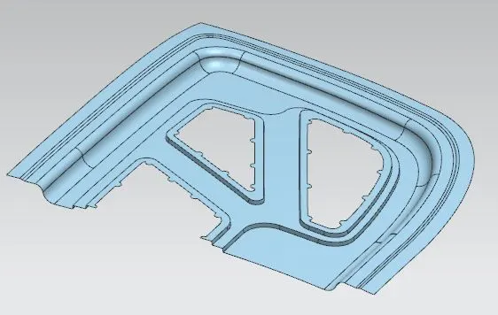
Select the profile and trim the part.
Now we adjust our hinge assembly and striker in position that we want and make profiles for their reinforcements. Project them to surface.
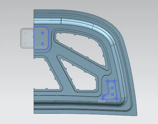
Keep the assembly little away from panel, so that we can add a vertical datum plane and emboss the same profile uptill that plane.
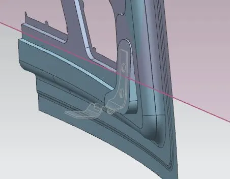
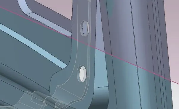
Eliminate the part that is needed for fixation. And you can see the assembly is well set to the embossed surface.
Latch Trajectory : It is simply the path that a striker will follow when the hood is being opened or closed. So, we have to keep it such way that it will hit the latch or the lock mechanism.
For this, we will create a line or an axis where the hinge will rotate. From the midpoint we will connect another line to the line of placement of our striker. The line from midpoint will make an angle with verticle plane and taking that intersection point we will create a circle which is nothing but the path of striker.
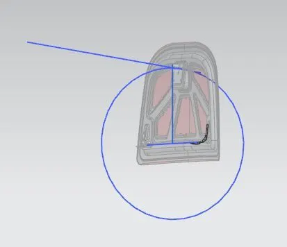
Then set a datum plane there and emboss the profile till that plane. Also, eliminate the fixture part.
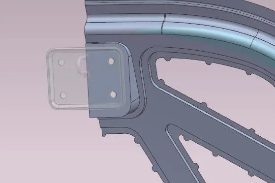
Now add face and edge blends to each and every sharp edge that got created by embossing or drawing. Also make sure to keep tangency realtion all over.
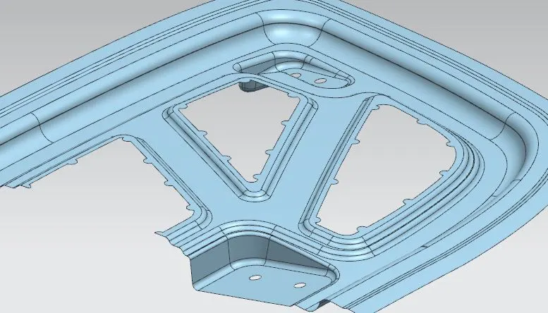
Before mirroring the part, we will extend the sheet which is highlighted, just to make sure we dont get any gaps later.
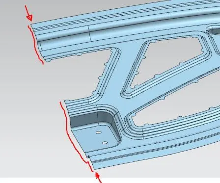
Now, trim the entire part with the datum plane which will be our plane of mirroring.
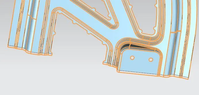
Trim sheet little bit for getting better hemming for the outer panel.
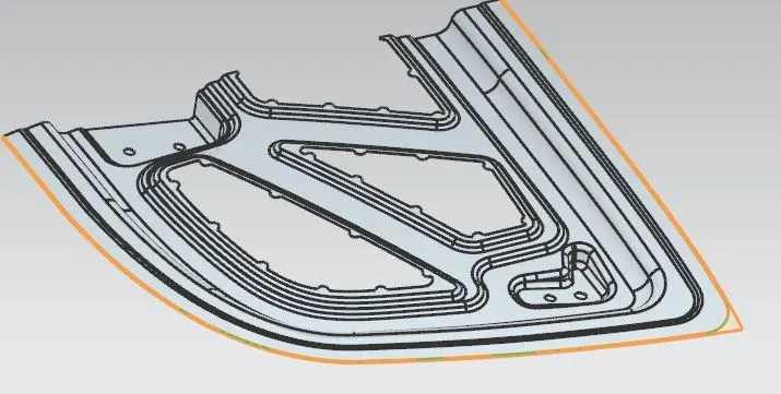
Mirror the entire model and sew it.
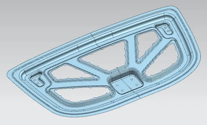
Now, finally we give thicken command of 0.75mm and we get our inner panel. Make sure the direction goes up.
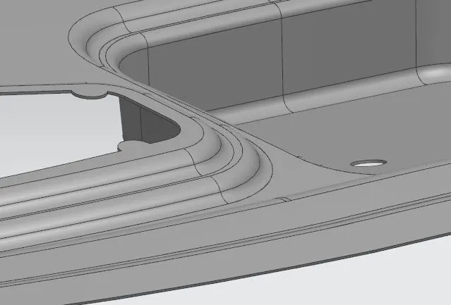
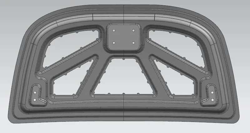
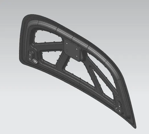
Now, we come to other part of designing the outer panel. So we start with the same body as default and trim that into half.
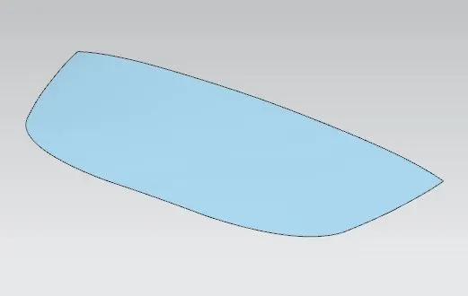
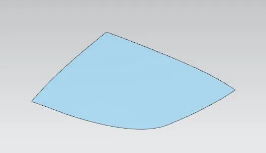
After getting the workpiece, take a curve offset and trim the part by 0.5mm.
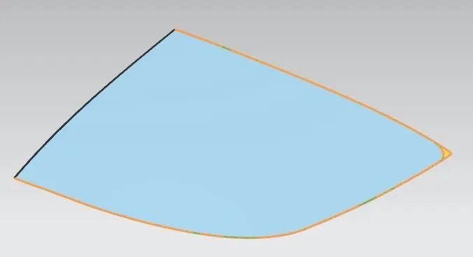
Extend the surface by law extension and keep draft of 5 degrees.
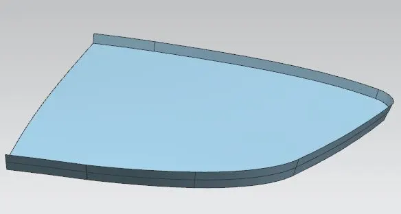
Now, take surface offsets of both the surfaces available. Here, for the law extended one we take 7.5mm inside and for the workpiece we take 2.8mm down. (keeping all the sheet thickness and gaps between them, we are taking 2.8mm)
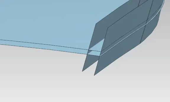
Trim the unwanted part of offsetted surface.
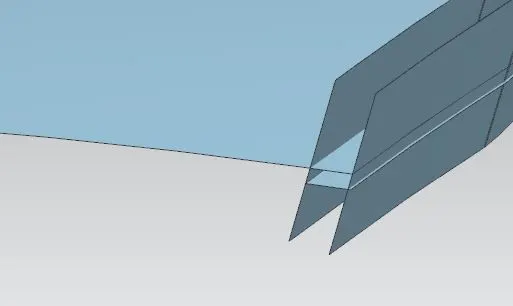
Now with the remaining three we create a face blend. The vector direction for upper surface goes down, bottom ones goes up and side ones come inside.
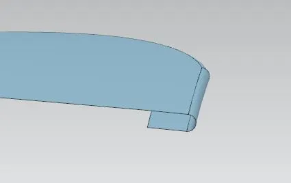
For this hemming we keep some relief at the rear end and front end too.
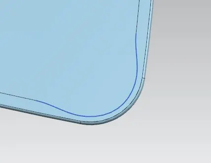
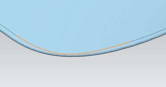
Now we can mirror the part to the plane and sew it.
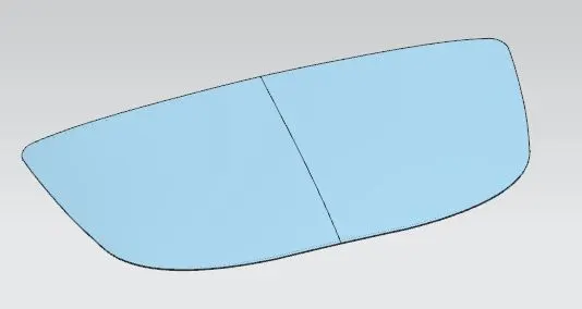
Give thickness of 0.75mm to the part. In this the direction goes down.
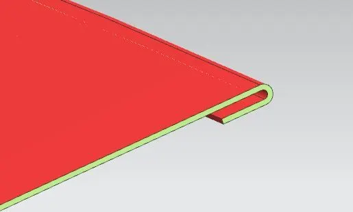
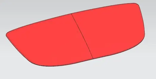
Now, we can assemble all the components together and can aslo set the contraints for striker and hinge assembly so that they dont have any freedon of moving.
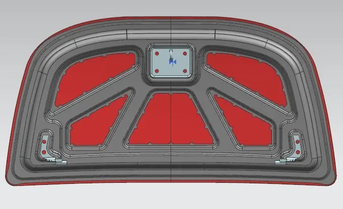
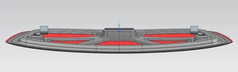
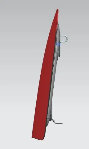
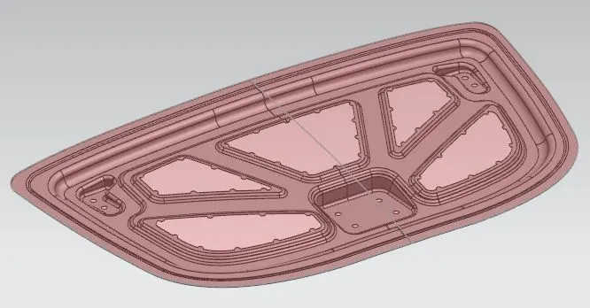
CONCLUSION : In this way, by following the procedure, we designed both panels and set the striker trajectory and the reinforcements necessary and learned the features used in curves, surface and assembly in Siemens NX.