Wiring harness routing & packaging Rules Week 3 Challenge
A. P Clamp
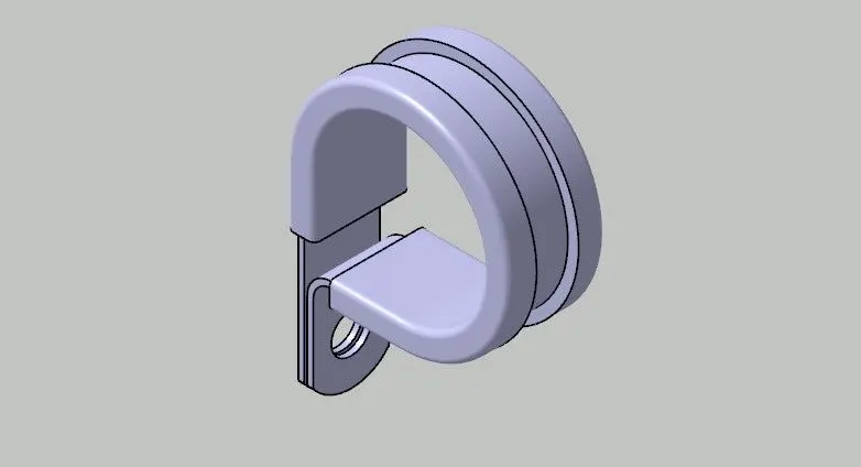
Aim is to define the standard component electrically. Here, we are provided with a P-clamp in .igs format, so load it into Catia V5. To make it an Electrical component follow the steps.
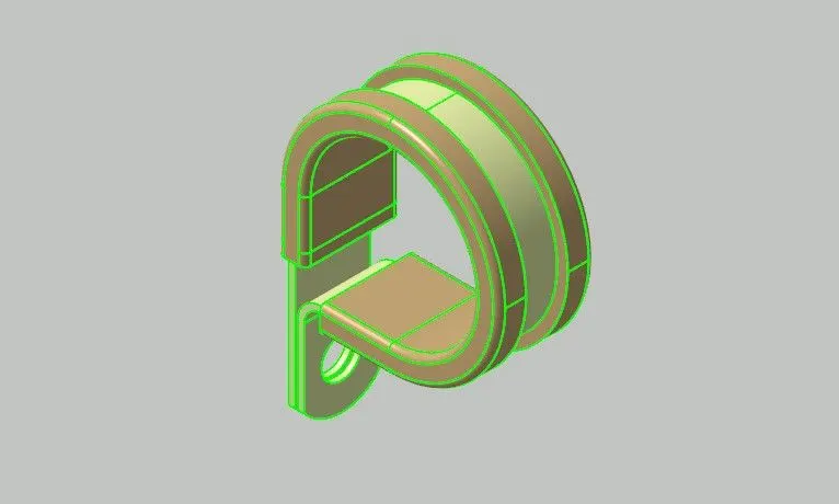
- Join the sub-surfaces together and convert into closed surface structure.
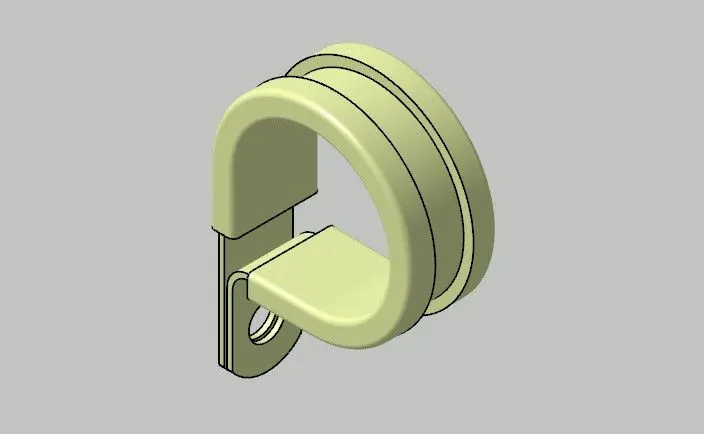
- Switch to Part workbench and solidify the closed surfaces.
- Identify the part, the path a bundle can follow (red or blue) and a base area where bundle will rest (yellow).
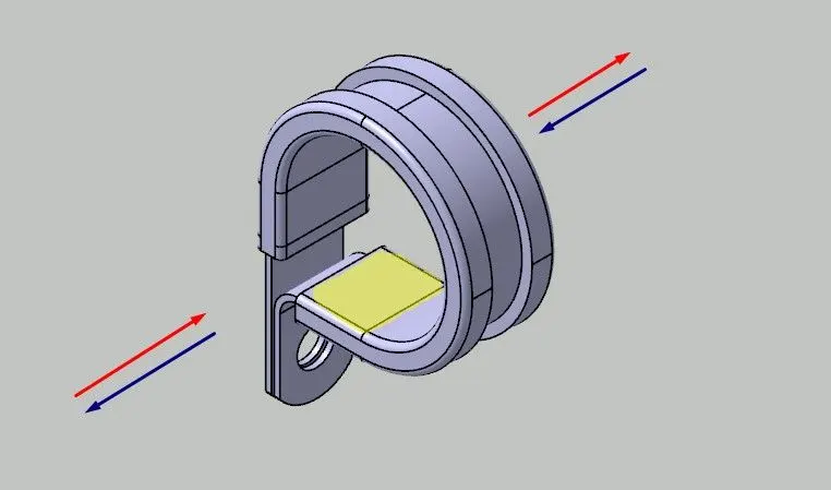
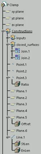
- First of all, create the geometrical parametres required.
- Create first point in centre of clamp at the extreme plane of body.
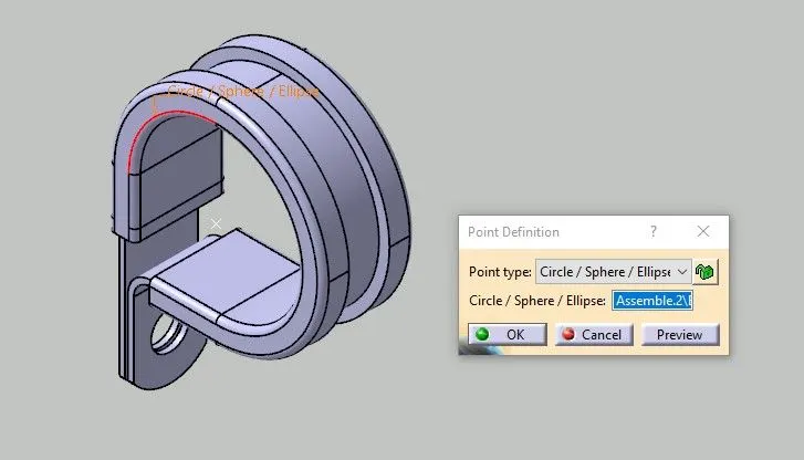
- Create second point in centre of clamp at the extreme plane of body.
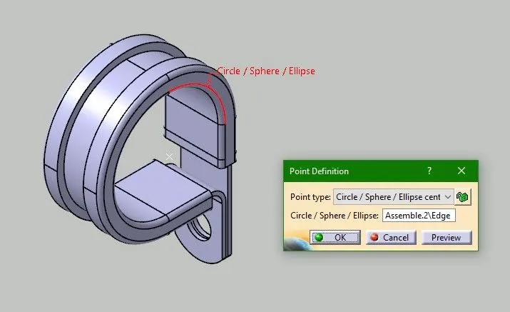
- Create third point at base as shown.
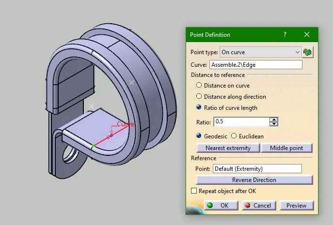
- Now create a first plane at first point following the extreme plane of body as shown below.
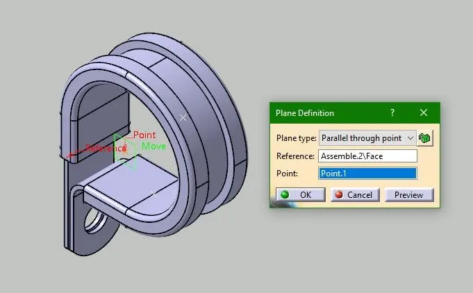
- Create second plane at second point following the extreme plane of body.
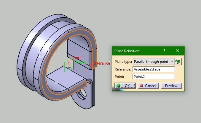
- Create base plane at base point following a flat surface.
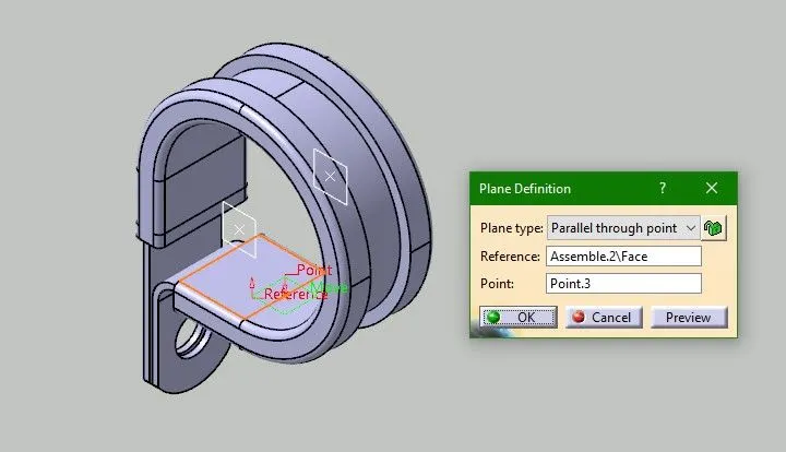
- Now all the geometrical parametres are created, so switch to Electrical Part Design workbench.
- To define the clamp component electrically, click on 'Define as Support' feature
 and then click on the component.
 - A window will open for the electrical parametres.
- Fill in the data as asked. We already created points and planes for this.
- First point and plane goes into 'first plane definition' and same for others.
- Click ok.
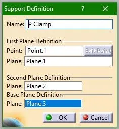
- Again select the same feature and click on the component and a window will open.
- This time select second point and plane as 'first plane definition'.
- Click OK.
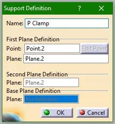
- The component is successfully defined electrically.
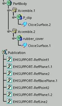
- Publications are available in the Feature Tree.
B. Back Shell for a Connector
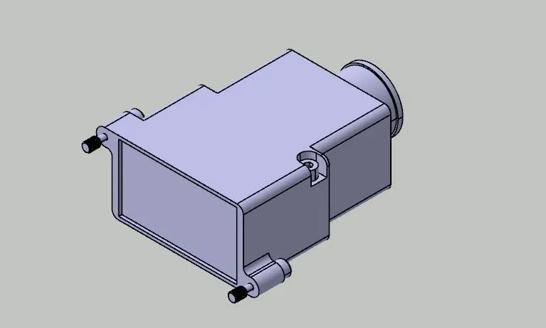
Aim is to define the standard component electrically. Here, we are provided with a Back Shell in .step format, so load it into Catia V5. To make it an Electrical component follow the steps.
- Look at the component and identify the bundle entry face and back shell connecting face. Before defining it electrically, we have to add some geometrical parametres.
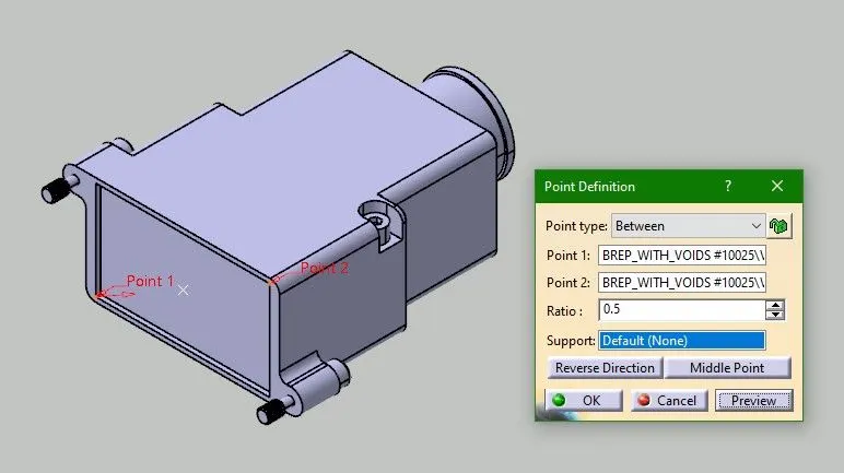
- Create a point in centre of face by using 'between option'. This is the Back Shell Connection Point.
- Add an Axis System on this point and follow the rule same as we do for connectors.
- Y-axis comes normal to the mating face and XZ plane along the face.
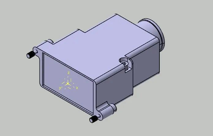
- Create a Bundle Connection Point in centre of the face.
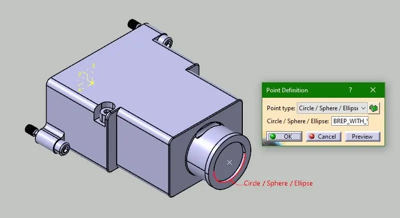
- All the geometrical parametres are created, so now switch to Electrical Part Design workbench.
- First of all, define the component as back shell by clicking on 'Define Back Shell' feature
 and then clicking on the component itself.
 - Click OK for the window that pops up.
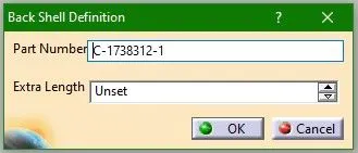
- Now, define the electrical parametres.
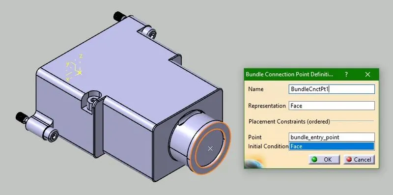
- Click on 'Define Bundle Connection Point' feature
 and click on component.
 - Select the first face that would come normal to the bundle as 'Representation'.
- Select the point which is created and the same face again for 'Initial Condition'.
- Click Ok and the parametres are added to feature tree.
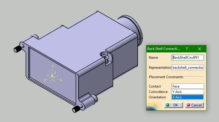
- Click on 'Define Back Shell Connection Point' feature
 and click on component.
 - Select the Back Shell Connection Point as 'Representation'.
- Select the mating face as 'Contact'.
- Y-axis comes as 'Coincidence' and X-axis as 'Orientation'.
- Click Ok and the component is Electrically defined.

C. COT Tubes
Aim is to create COT Tubes and add them as Catalog entity.
- To start with, open Electrical Part Design workbench.
- Select 'Define Protection Part' feature
 and as nothing is there is window, click on part name
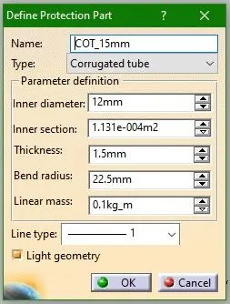
- A window will open up asking all parametres.
- Select Corrugated tube as type.
- Insert values as required for Inner diameter and Thickness.
- Bend radius will be 1.5 times the outer diameter.
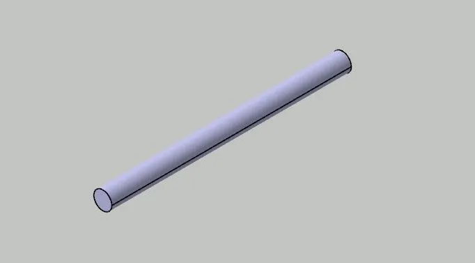
- Click OK and a solid part is created with same dimensions.
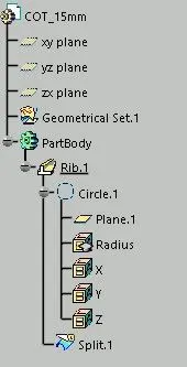
- Save the CATPart file and then click on 'Store device' feature

- Select the catalog from the system and the required family and hit OK.
- The same is stored in catalog and can be used later in Assembly.
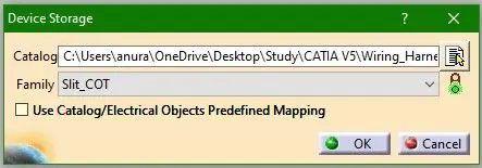
- Similarly, do this for other dimensions as well and add them into catalog.