Door Arm Rest Week 8 Challenge
DESIGN OF DOOR ARM REST
Aim : The main objective here is to create a Door Arm Rest plastic component from a given Class A Surface and validate the design by doing Draft Analysis on it.
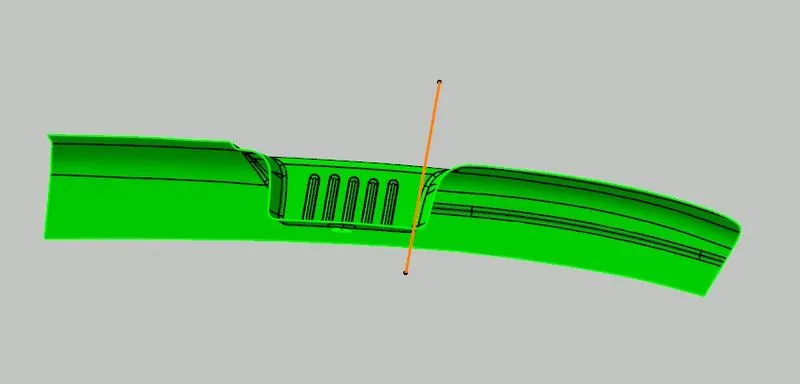
The approach towards it will be simple. We will create a closed surface and later solidify the component. To start with, lets create a tooling axis first. The CAS is a bit complex here. We can see a bin (a pocket kind structure), top and side flanges.
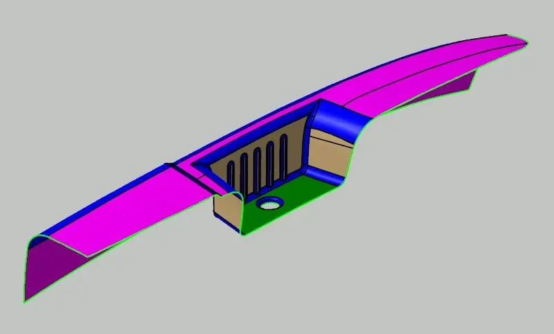
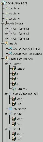
Looking at vertical flanges which are compactly together, we have to find a way through them. So, extract the top surface and take a point in between two surface planes and add an axis system. Create a line that passes through origin and along an axis kind of normal to surface. This is a dummy tooling axis.
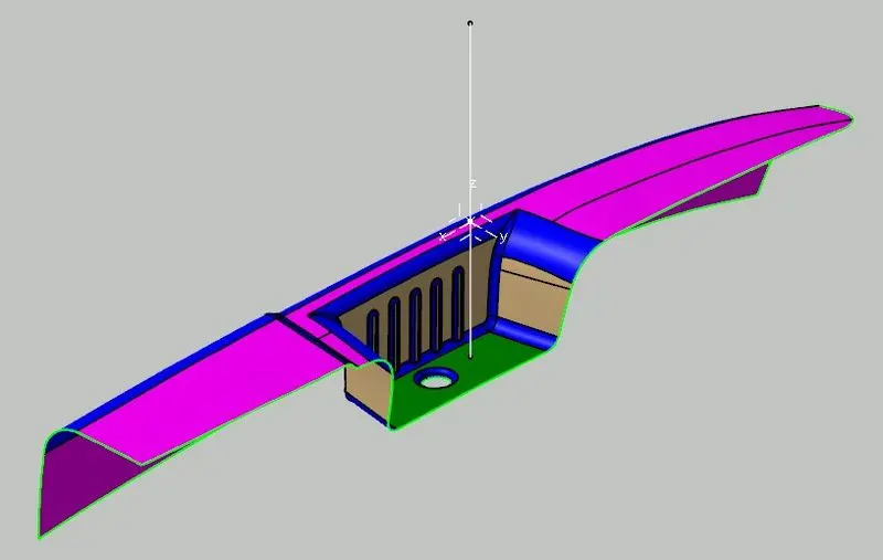
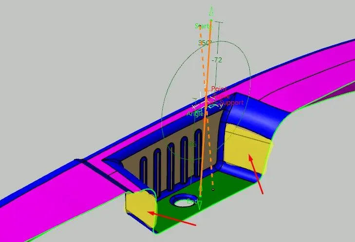
Here, for Y-direction clearance take an intersection of YZ plane and the CAS. We can notice that the highlihted walls can disrupt the ejection of component.
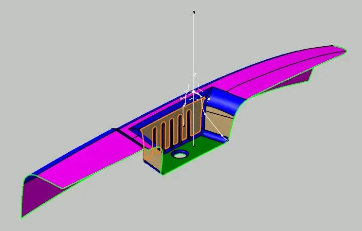
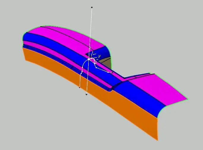
Draw lines along the wall instersection entities and take a bisection of them. This will act as a Y-direction clearance tooling axis.
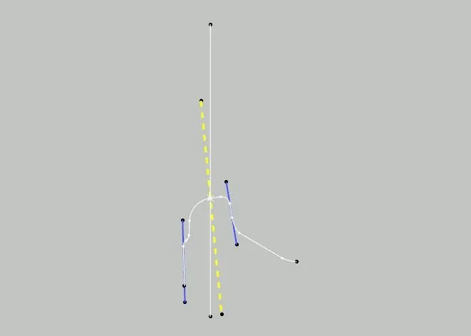
For X-direction also, we can see highlighted walls that can occur an issue, so simply add a line at some angle for a better clearance. Here, we took Y-direction clearance axis as reference, XZ plane and defined origin as supports and gave angle of 10 degrees.
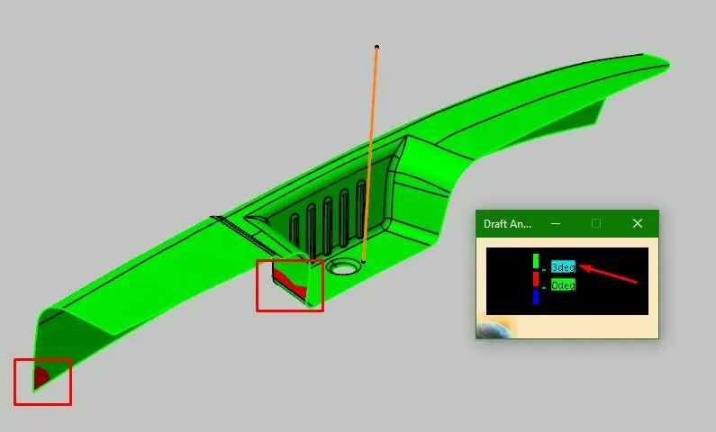
To ensure if the tooling axis is perfect, lets do the draft analysis for CAS. Drag and drop the compass along the tooling axis and analyse the surface for 3 degrees draft angle. Almost 95% of the CAS shows green, but has two portions where it is showing red surface. That means draft value is somwhere between 0 to 3 degrees.
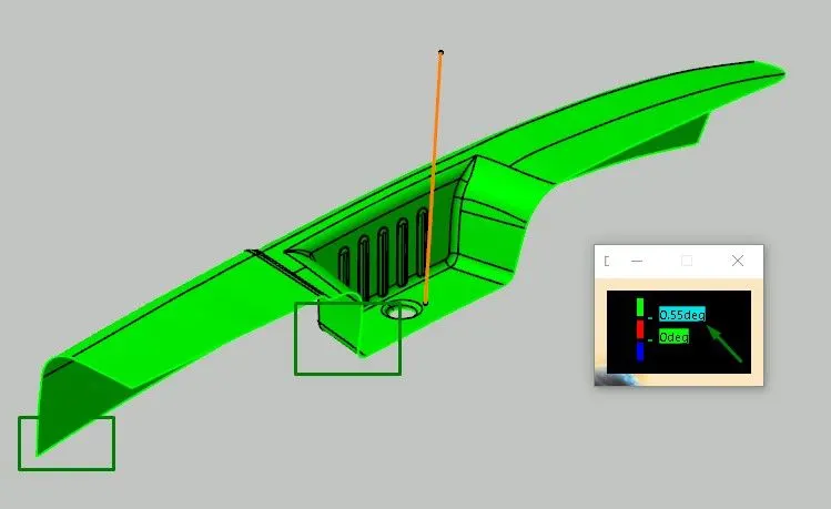
After, lowering the value to 0.55 degree, it turns up green fully. Also, we know the minimum draft angle that should be provided is 0.5 degree. So, entire surface gets clearance through main tooling axis only and there is no requirement of side tooling axis. If needed, we can ask the CAS designer to modify those red portion areas a little, so we can get clearance for 3 degrees as well. Right now, we can proceed with the same tooling axis.
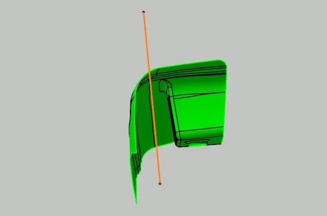
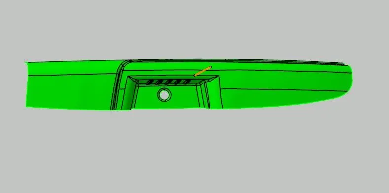
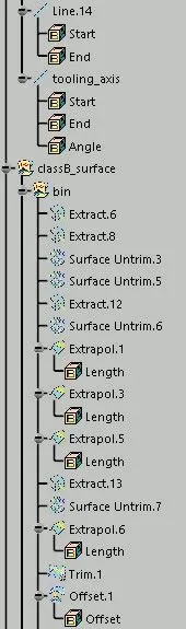
Now, let us move further and create Class B surface. For this, neglet the fillet surfaces and focus on other surfaces. First of all start with bin walls and extract them. After extracting, to get a uniform shape, untrim them and extrapolate adequately. Take offset of required thichness (here it is 2.5mm). Make sure the offset direction is correct and the produced surface is towards inner side of the component.
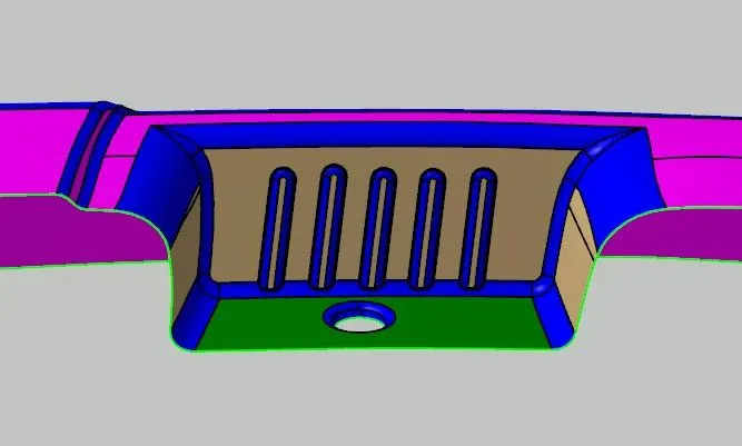
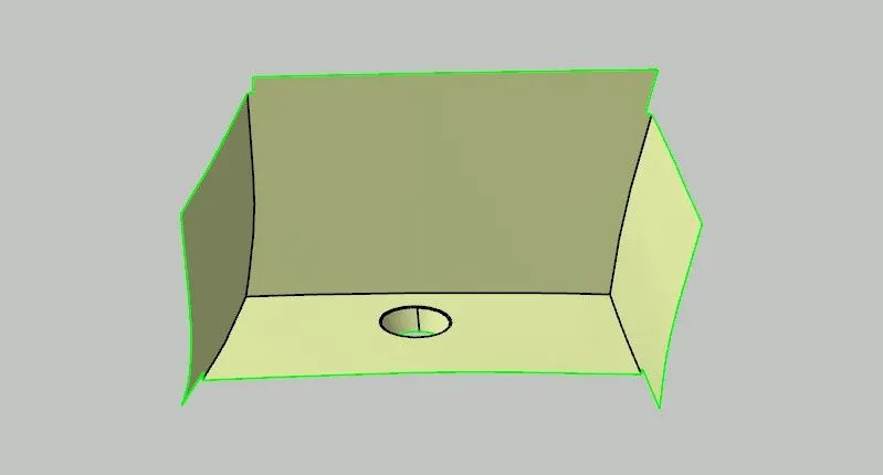
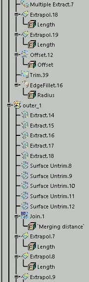
Lets divide the other part of the CAS into three. Outer 1, outer 2 and the connector. Continue the same process for the two outer surfaces. Do not trim them along yet as the structure is little complex.
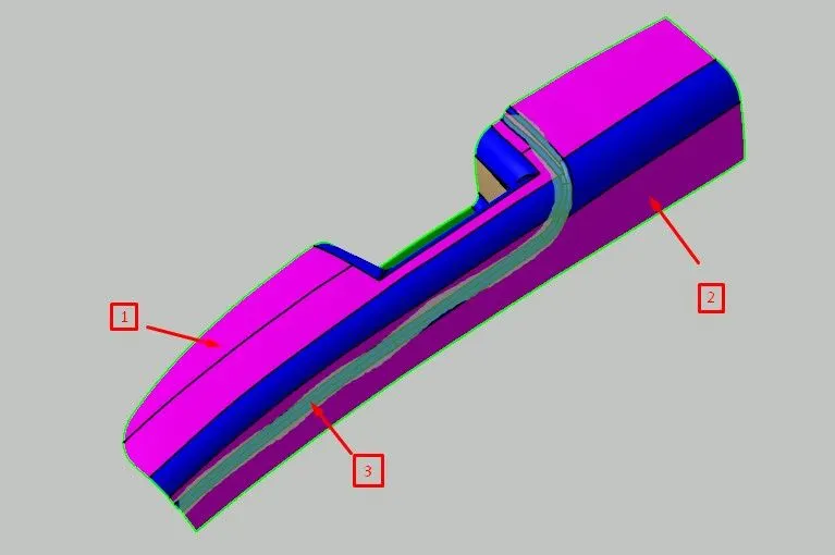
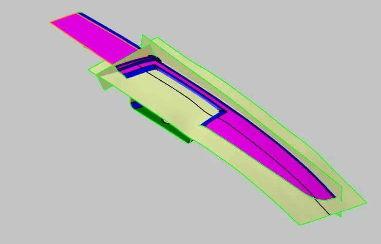
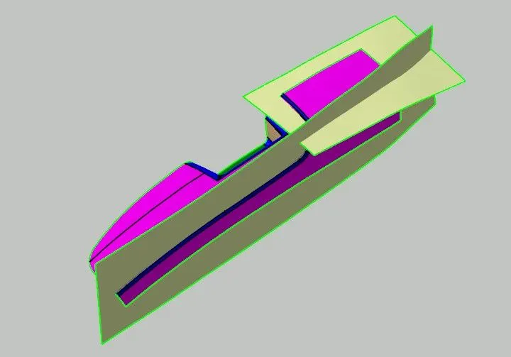
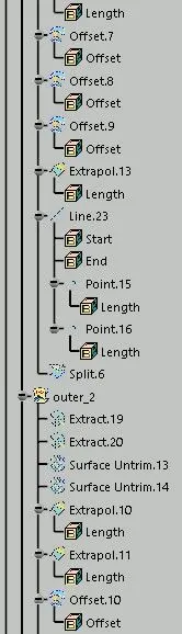
As you can see in connector section, there are two filleted surfaces which means there has to be another plane surface. So to create it, add a point and axis system and create a line as shown. Take an intersection of surfaces and constrain the line tangent to it.
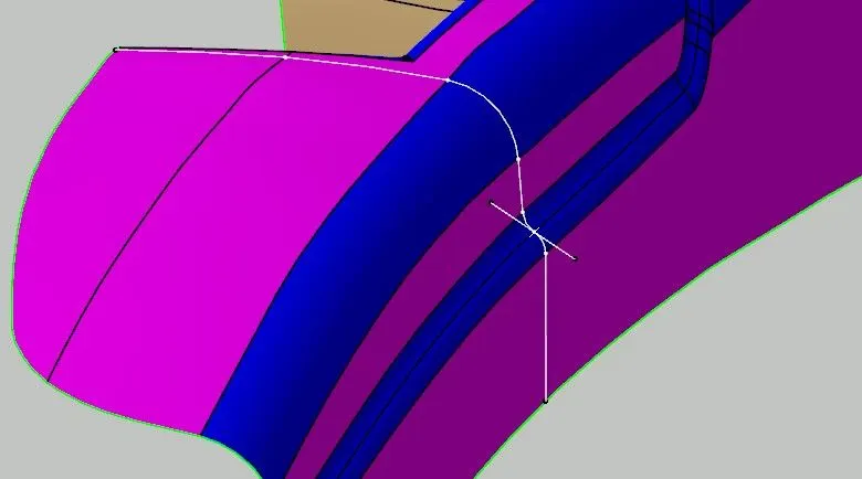
Multi-extract the middle curve and use sweep feature to create a surface as shown.
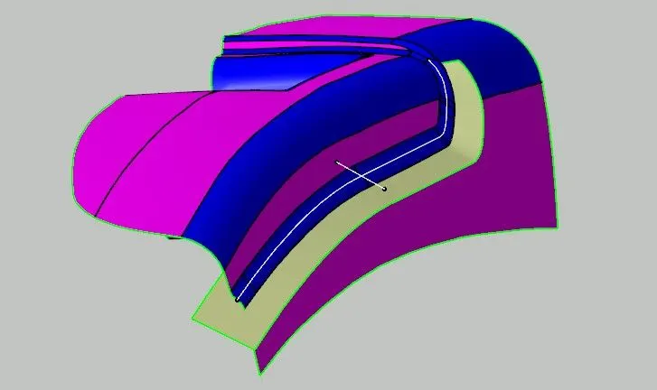
Now, to blend the surfaces well, trim them a little and use blend feature. Make sure to keep tangent surface support.
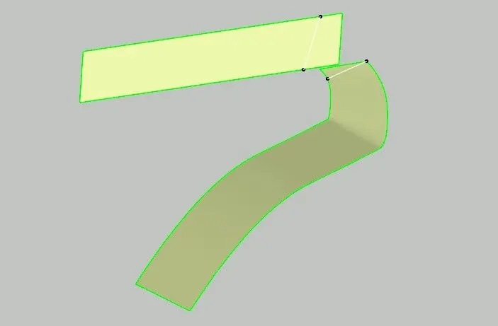
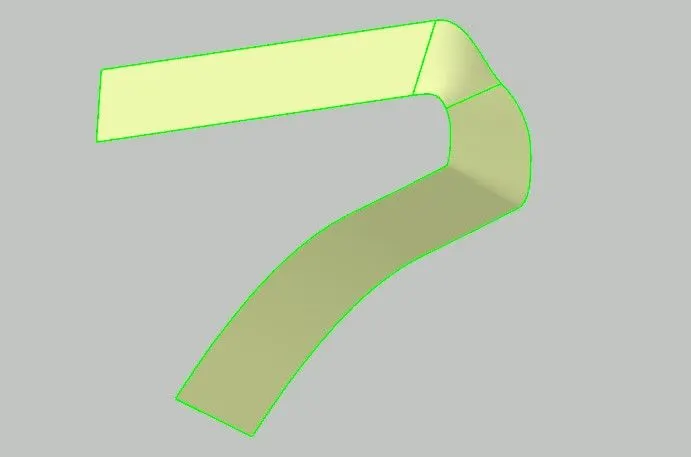
Now, we can trim all the surfaces appropriately and fillet the edges. For filleting the edges in Class B surface, if it is difficult to measure the fillet radius in CAS as the profile varies, use a different method. In this method, extract the fillet surfaces and untrim them. Measure the radius value at the edges which will give the correct value. Our Class B surface is ready, just needs some trimming from sides.
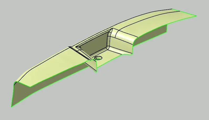
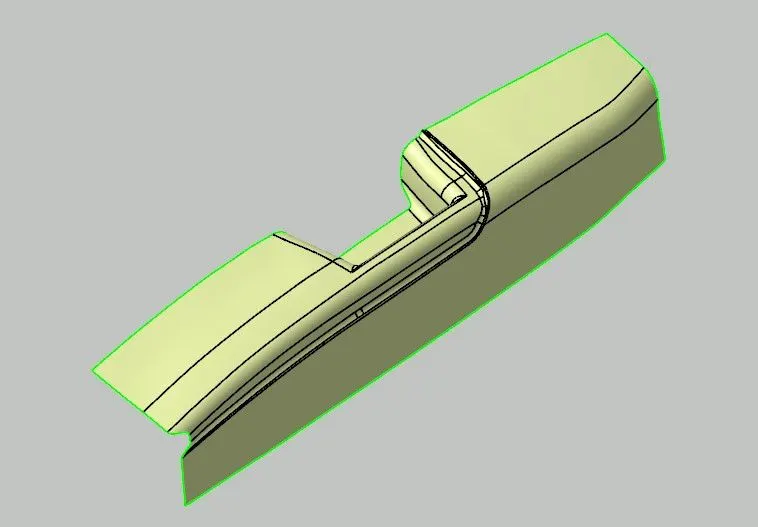
For this, lets create Class C surface, which will also enclose the surfaces. Sweep the boundary of CAS towards class B along the tooling axis and keep a draft angle. Here, required draft angle is 3 degrees, so we are taking 5 degrees safely. But we can see, some edges dont give what we exactly need because the class C surface should go normal between the other two surfaces. So, do the process for the only edges which gives appropriate surface extentions.
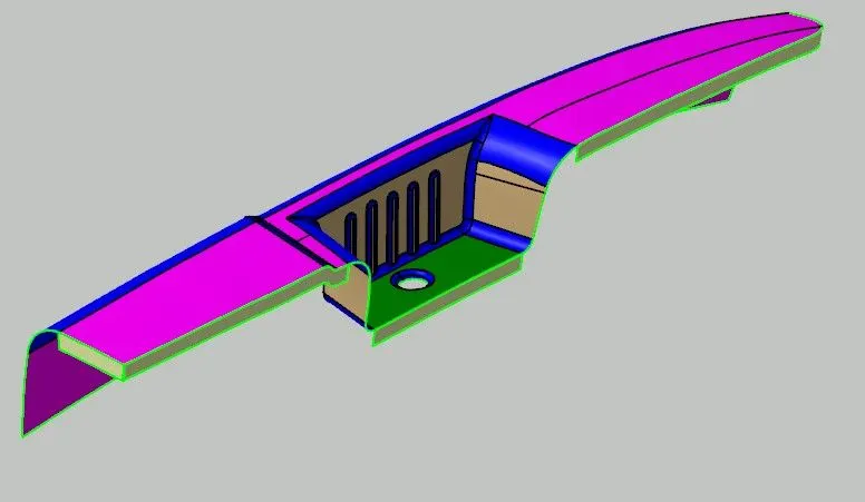
For other edges, try the sweep with surface as a reference as shown below. And for the intermediate and complex edges use muti-section surface feature. At the end, the surface created should be able to trim off the class B surface.
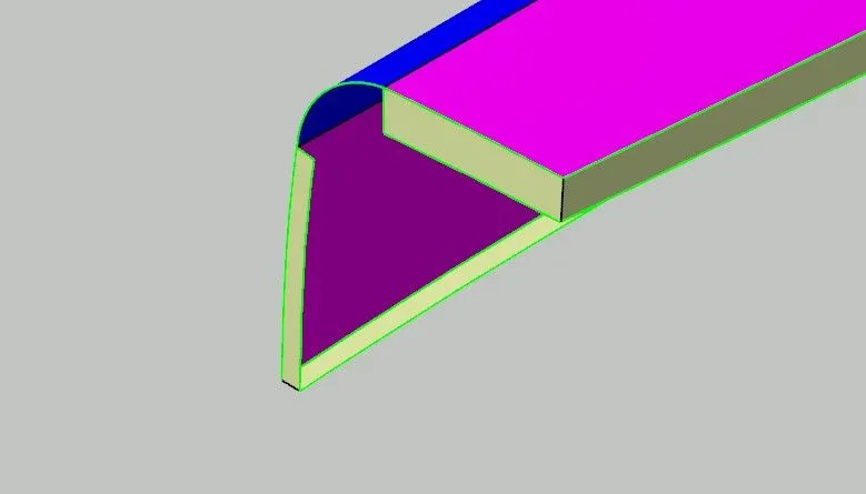
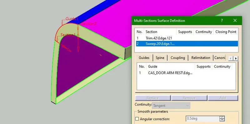
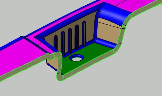
Here, the parting line will be along CAS and in situations of flashes, aesthetic surface's edges might get a hand operation. But as this part will be assembled so, the edges wont be open. So, we can opt the clearance of class C with class B surface.
Join both the surfaces and trim it along Class B surface. A final closed surface of component is created which is shown below in pink.
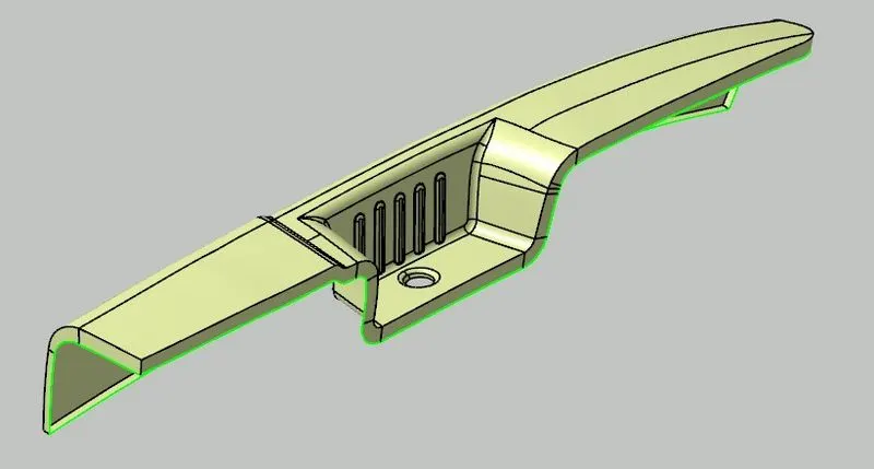
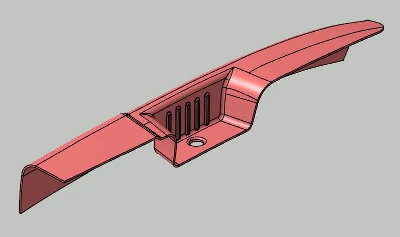
Switch to the part workbench and make the closed surface into solid part which is our final Door Arm Rest plastic Component.
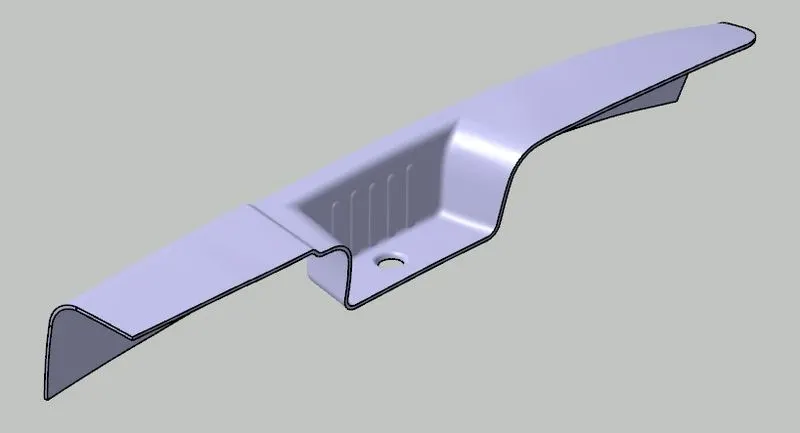
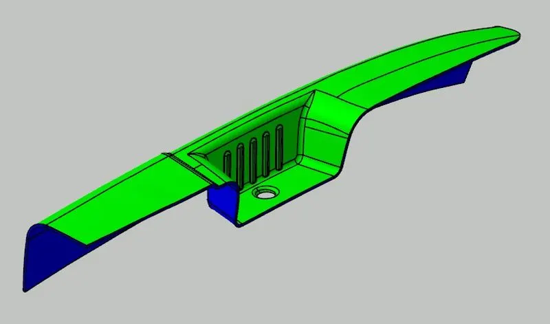
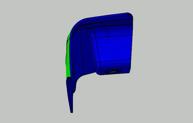
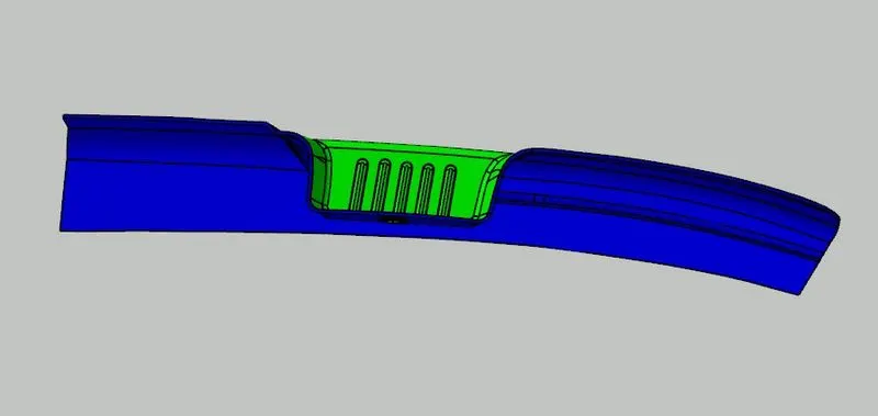
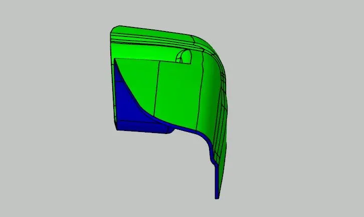
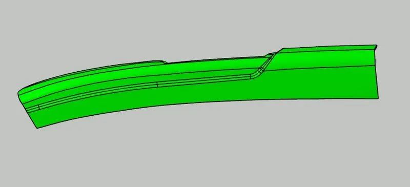
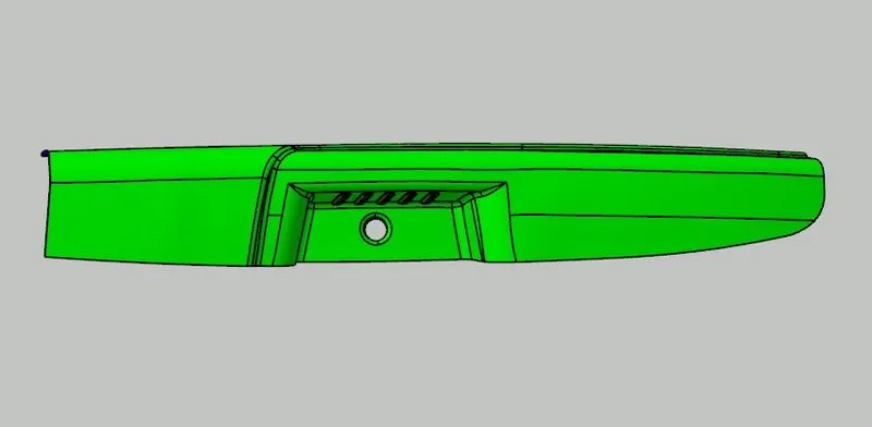
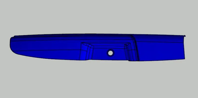
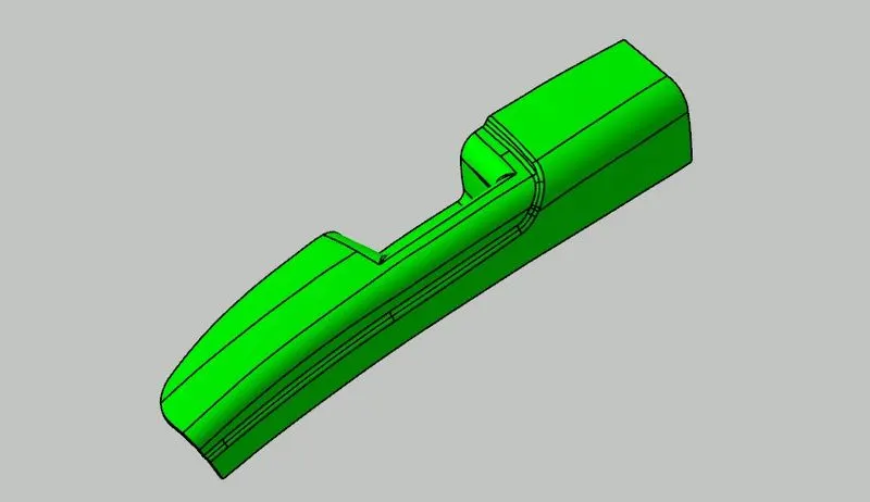
Lets ensure the design by draft analysis. Drag and drop the compass along the tooling axis and click on the component. Here we are getting all green over Class A and blue over class B & C, that means the design is fine and will get ejected easily.
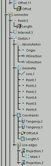
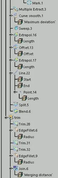
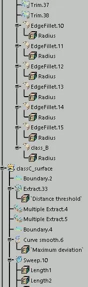
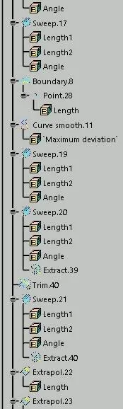
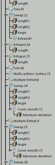
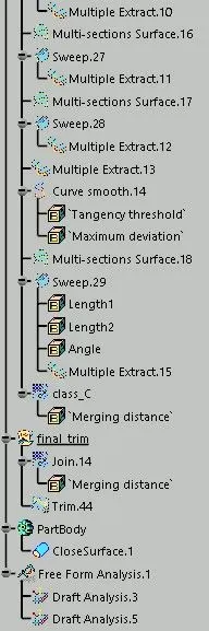
Tree Structure