Week 9 - Project 1 - Door Applique Design with Engineering Features
DOOR APPLIQUE
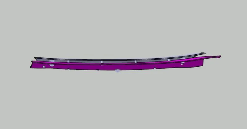
The aim here is to design a door applique plastic component from given Class A surface and create locators and heat stakes for the same. Given are the surface inputs.
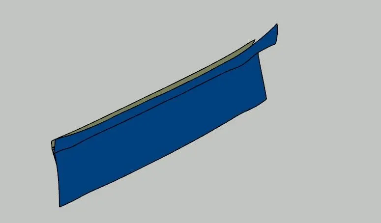
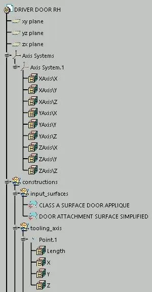
First of all, create a tooling axis for the surface. Follow the steps as below :
- Add a point on a larger surface in centre and an axis system at the same point.
- Create a line passing through origin.
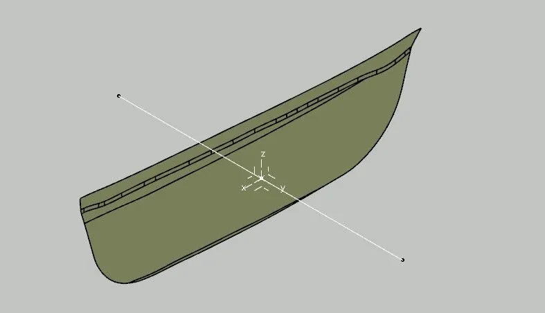
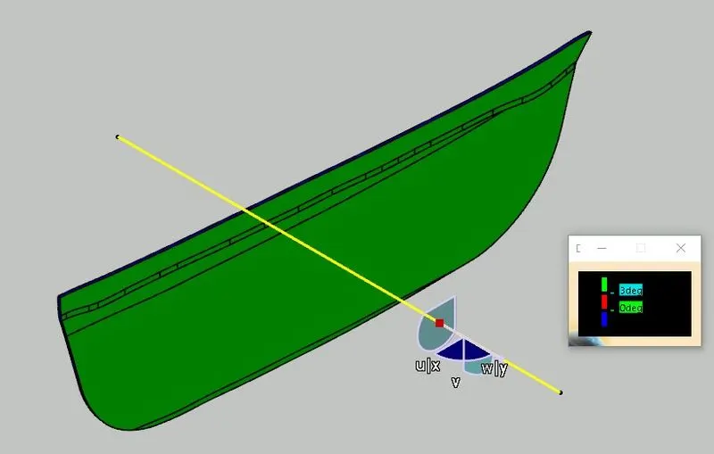
The entire class A surface looks almost normal to the line and no adjacent walls are there that can create an issue while ejecting the part. So will do the draft analysis for the same line.
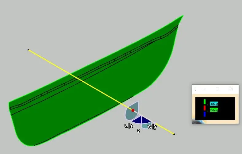
- Select 'Draft Analysis'
 and drag and drop the compass along the line and clich on the surface.
The surface comes out green completely, that means the created line is a perfect tooling axis for the component.
Now to create class B surface, follow the steps as follow :
- Switch to Generative Shape Design workbench

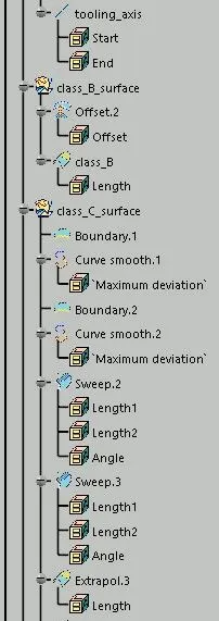
- As the CAS is simple, take an offset of the same by clicking on 'Offset Surface'
 and as required thickness, put value equals to 2.5 mm.
 - Extrapolate
 the surface for all edges.
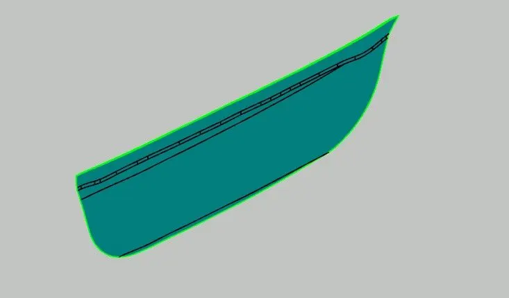
- To create a closed surface body, class C surface is needed for which extract boundaries of CAS by using boundary feature

There are a lot of points in the curves which can divide the class C surface into sub-surfaces when formed. To solve this problem, convert them into Smooth Curves by using the Smooth Curve feature 
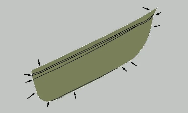
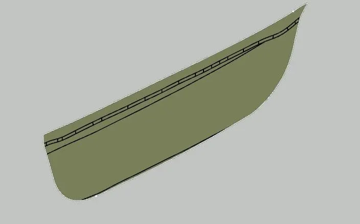
- Now select 'Sweep' command and sweep the curves along the tooling direction and make sure to select the direction accurately, where the class C surface gets clearance along the class A surface.
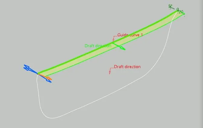
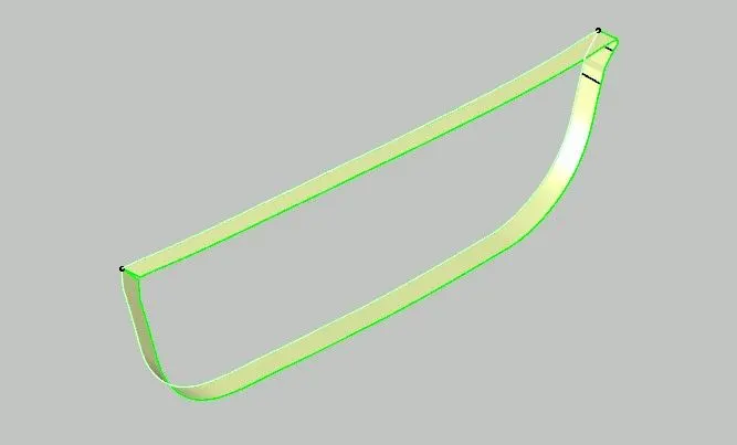
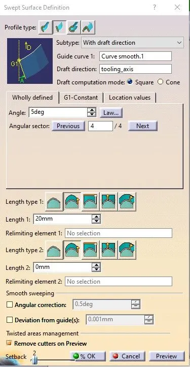
- If any irregularities are there, can extrapolate the surface with same curvature and trim the unwanted surface off using 'Trim'

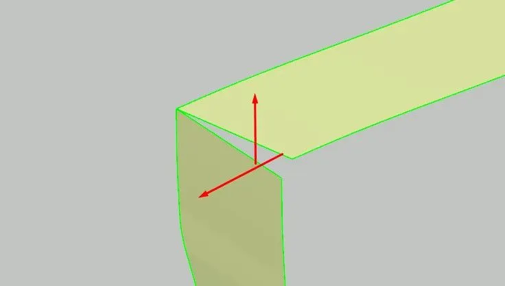
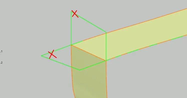
As, the class B and C surfaces are ready now, do the final trims and create a closed surface body.
- Join the Class A and Class C surfaces by using Join command

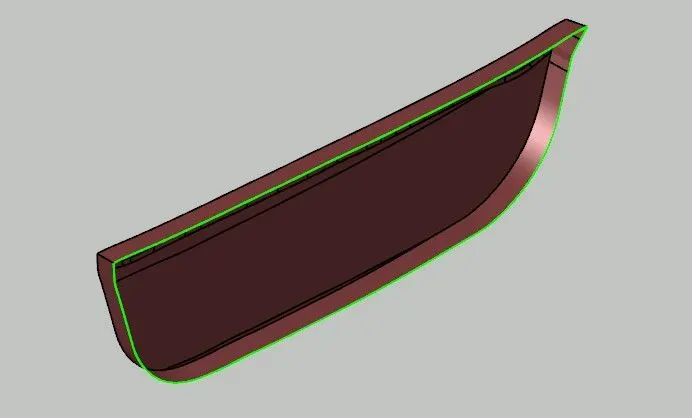
- Trim the joined surface with class B surface and a closed surface is obtained. make sure no open boundaries are left.
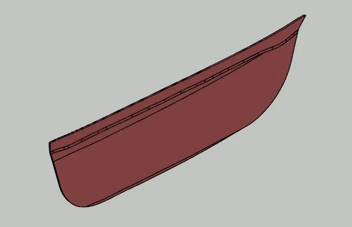
- Now, switch to Mechanical Part Design workbench
 and solidify the closed surface by using 'Close Surface'
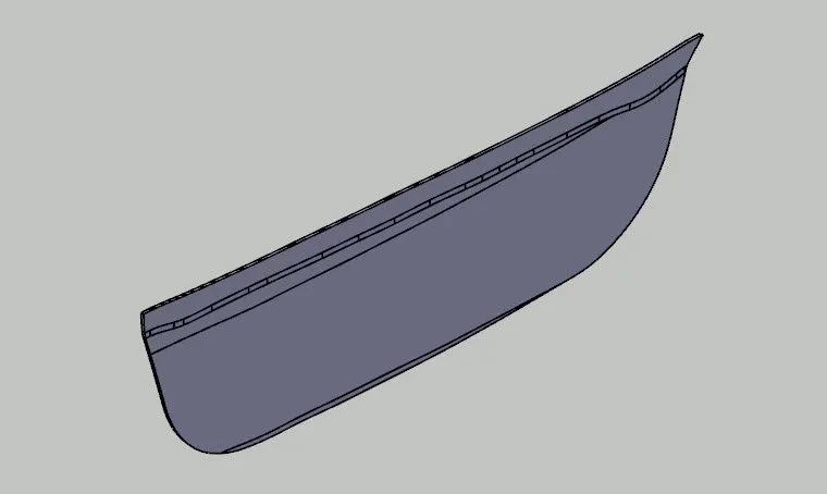
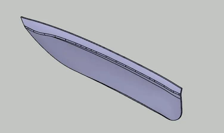
- Do the draft analysis for the plastic component too, by following the same steps.
- Entire surface turns out green, that means the created part is manufacturable.
- Also we can observe that Class A and C get clearance together, which means there will be no flash along class A edge.
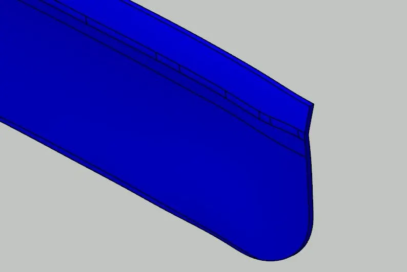
Next step is to work for the locator pins and heat stakes. First of all, thicken the door trim surface (here 2.5mm) by using 'Thick Surface' 
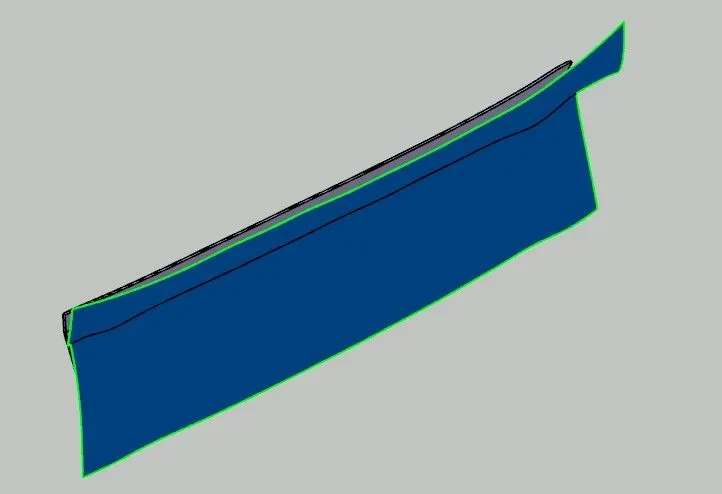
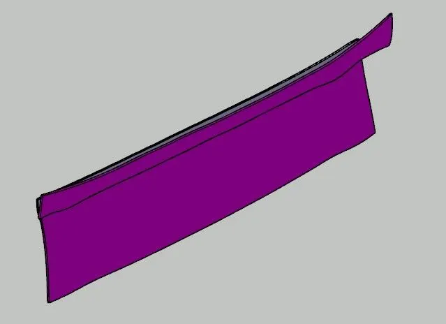
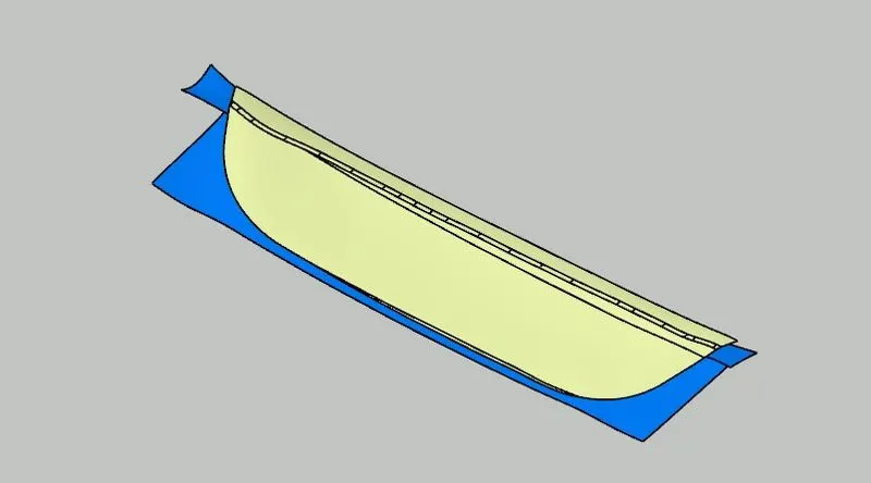
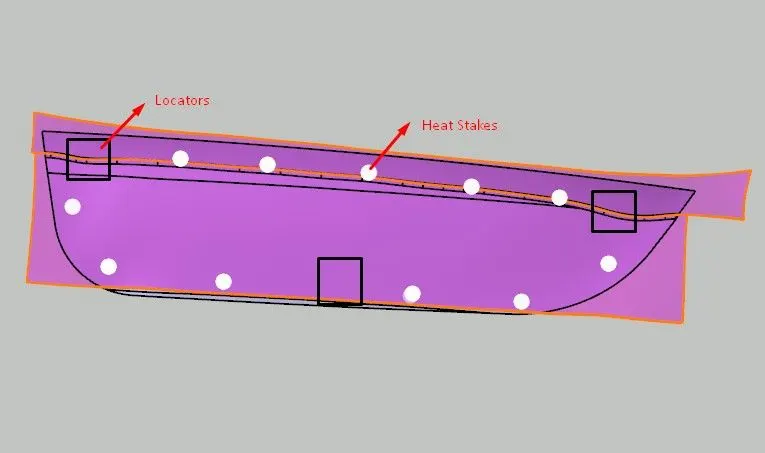
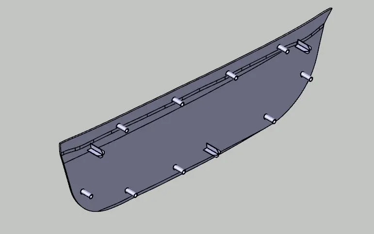
As we are aware about the degrees of freedom a component can have i.e. 12 DOF, 6 translation and 6 rotational. Here, for locators we will fix 11 of them and leave only 1 as the fitting direction. Three are more than enough to fix any component, so as ashown below, we will locate them there. To seal the component with another part, around the edge we will provide heat stake points as shown is white circles.
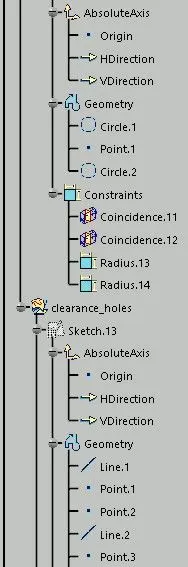
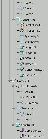
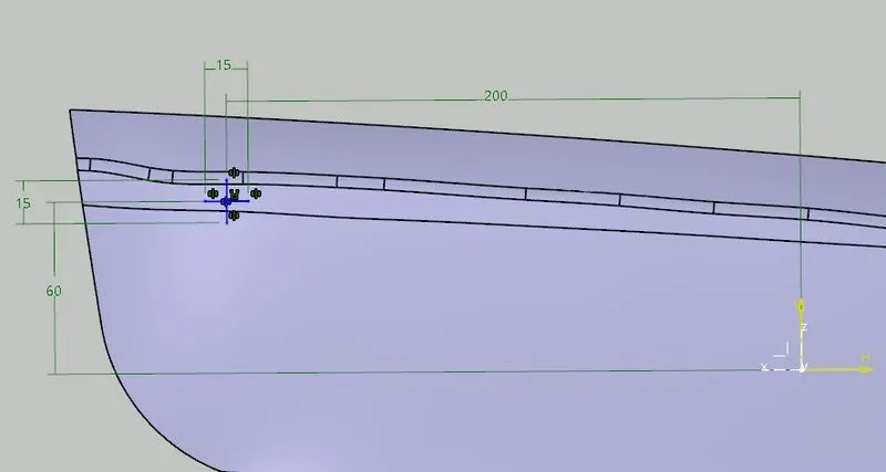
- Create a sketch
 as shown. This will follow the rib design parameters.
- From the Part Design workbench, select the 'Pad' feature
 and select the created profile.
 - Use the 'Thick' feature to give thickness to ribs. Make sure the part passes through the door trim component.
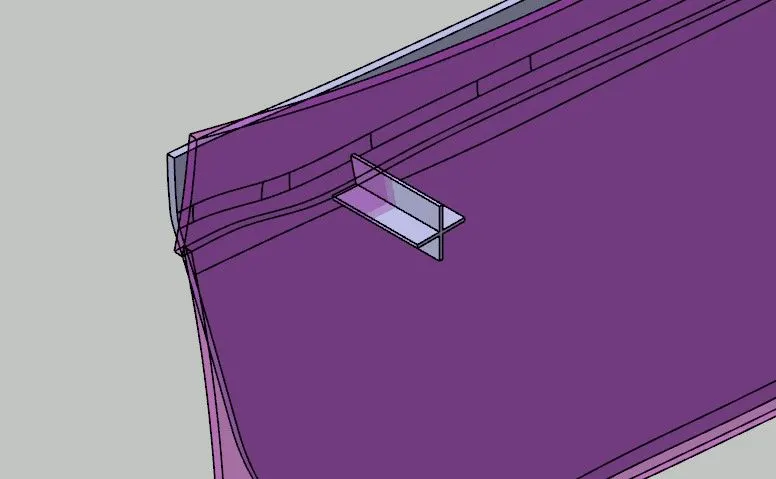
- Use 'Draft Angle'
 to provide minimum 0.5 degree of draft.
 - Use 'Chamfer'
 and 'Fillet Edges'
  to give shape to the part.
 - Copy-Paste the same locator pins and translate them in different corners of the Door Applique.
- Use Union-Trim option and make sure the tips has the same distace from the surface so that they together come in contact with the Door Trim part.
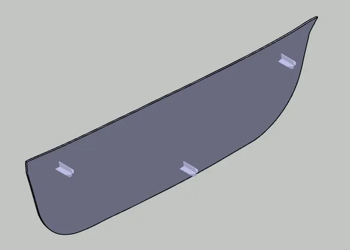
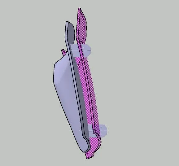
- As we want the position of heat stakes along the edge, use the parallel curve feature and offset the boundaries over the surface.
- Add points on the curves at equal distance, as heat stake points. They should be normally 50-100mm apart.
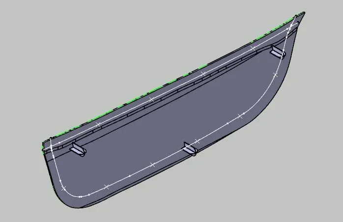
- Create a sketch for boss as shown and pad the same. Make sure to keep the tip around 5 mm deeper than the Door trim surface.
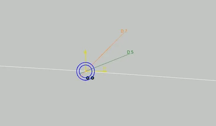
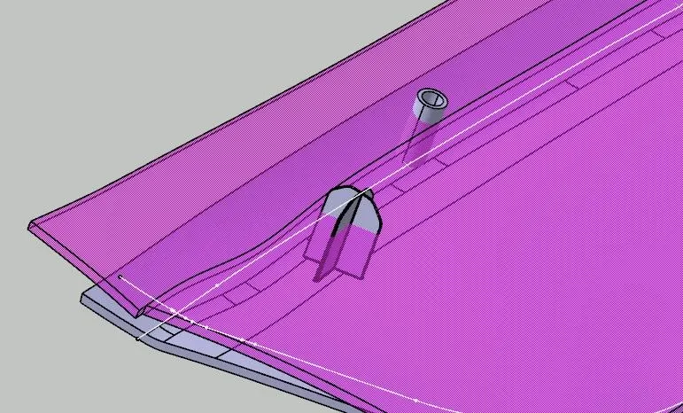
- Follow the rules for boss, like 40% wall thickness, 0.5 degree draft, 0.25mm fillet radius, etc.
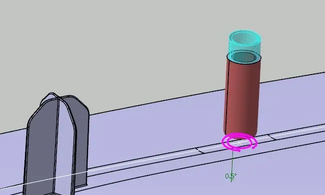
- Paste special this boss along all the points, assemble them together and Union-Trim the assembly with the main component.
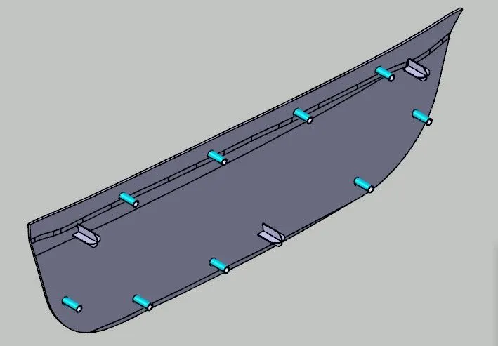
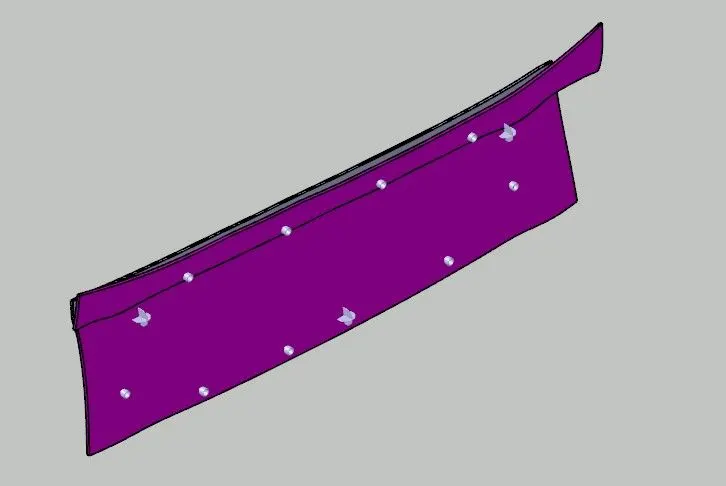
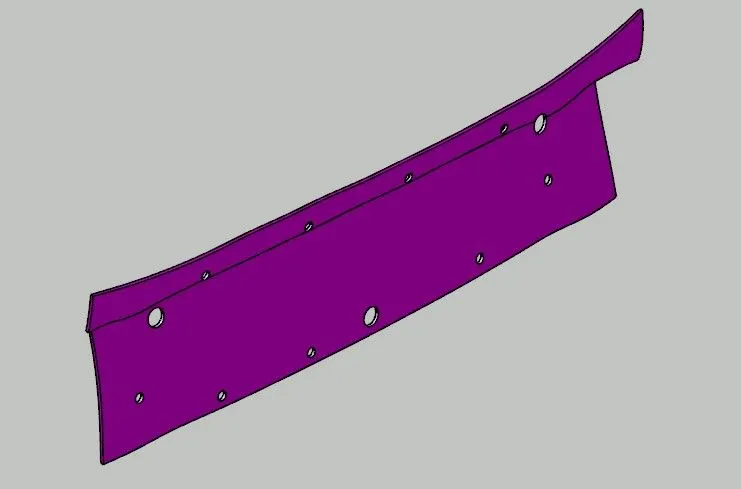
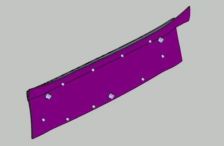
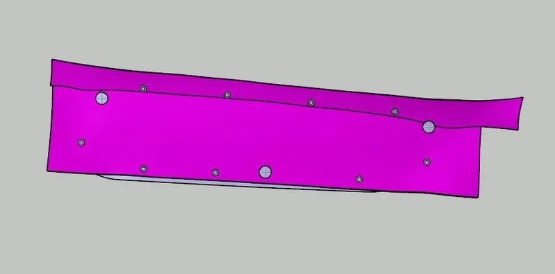
- Now the clearance for all the pins is needed, that is nothing but the holes for the pins in Door trim part, so that they can pass through them.
- Create sketch and pad the profile and remove the material from the main door trim component. The steps will remian the same.
- Make sure to give tolerance, so teh pins can easily slide into the provided holes.
- Give 0.1mm gap for locator pin for all sides and 0.5mm for the heat stake pins.
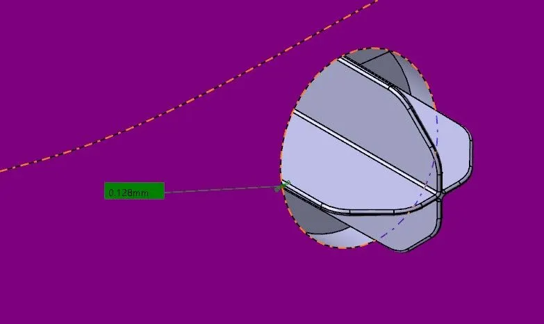
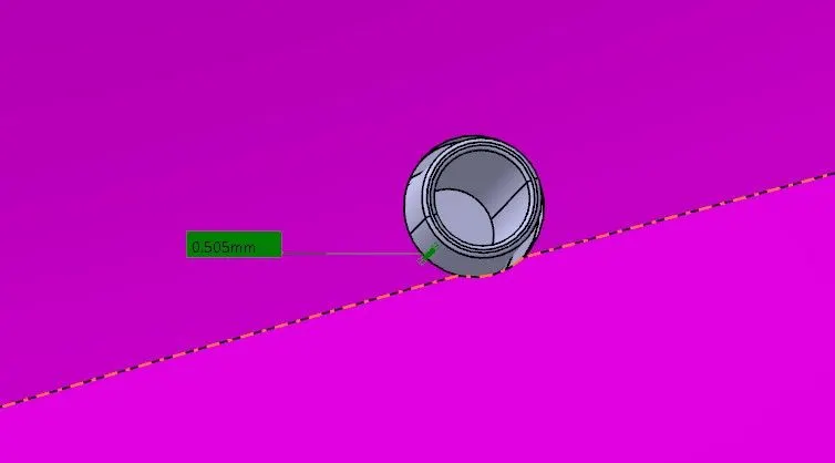
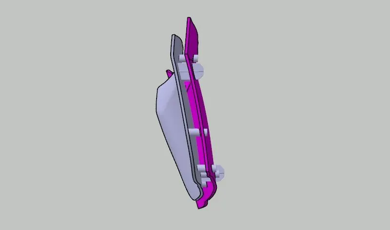
- The entire assembly is created perfectly.
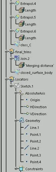
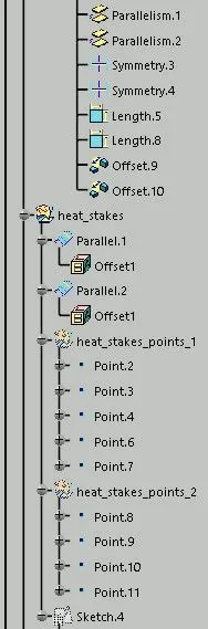
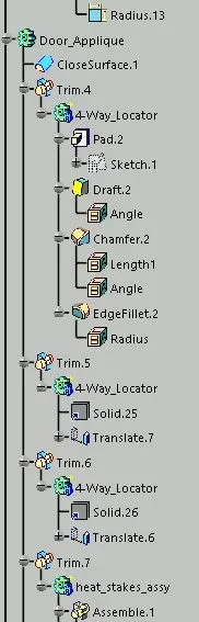
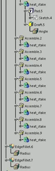
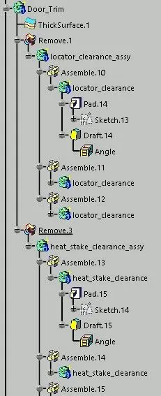
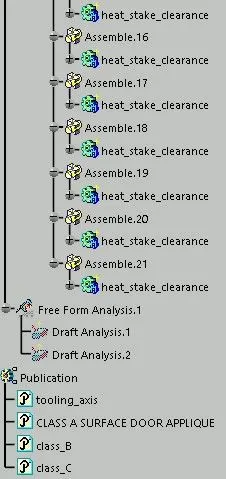
Tree Structure