Advanced Sheet Metal Design Using NX Cad Challenge_2_Box Assembly
SHEET METAL BOX ASSEMBLY
The Objective of this project is to create a sheet metal box assembly by using modelling tools and features and also learning about them in Siemens NX-12.
Introduction : This report is a step by step explaination of designing a box assembly by Siemens NX-12. Also, all the features applied while designing are explained briefly.
The Approach to the design is simply shown in the form of flowchart.
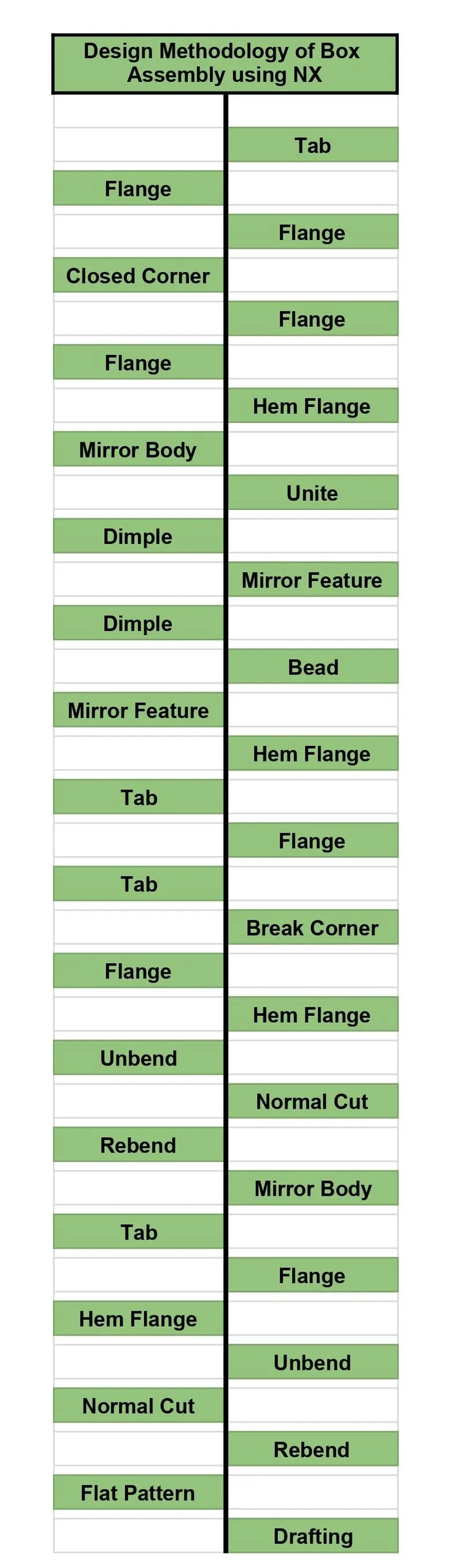
Description : NX sheet metal is opened and no such global parametres are set as preference, because normally local entries will be used. The features applied step by step are as follows :
- Tab : This is used to create a base by extruding a sketch in particular direction or simple adds material to a sketch giving thickness.
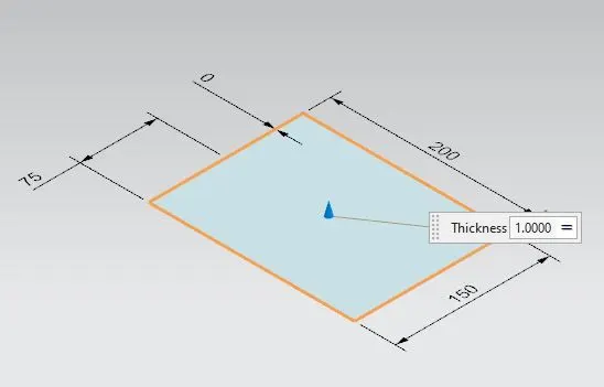
- Flange : It adds a flat flange with an angle to a plane surface and adds a bend in between two.
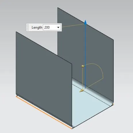
- Flange : It adds a flat flange with an angle to a plane surface and adds a bend in between two.
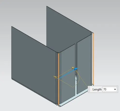
- Closed Corner : This is used to fill a corner where two adjacent flanges meet by extending the bends and flanges.
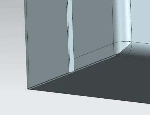
- Flange : It adds a flat flange with an angle to a plane surface and adds a bend in between two.
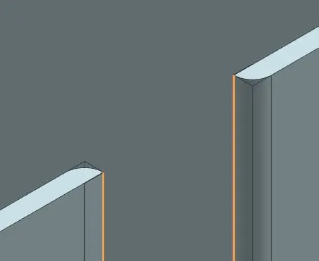
- Flange : It adds a flat flange with an angle to a plane surface and adds a bend in between two.
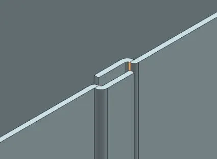
- Hem Flange : This adds an overlapping edge to an existing flange itselt in order to increase edge stiffness or for safe handling.
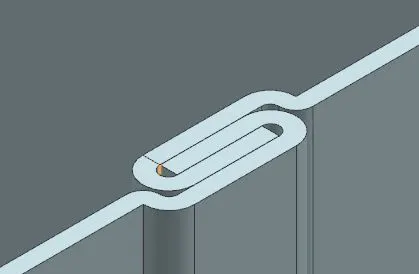
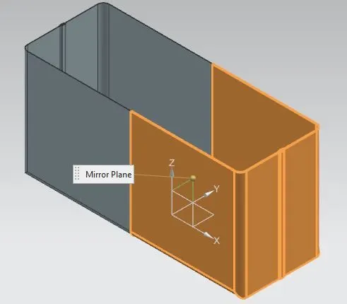
- Mirror Body : It is used to mirror a body along a plane.
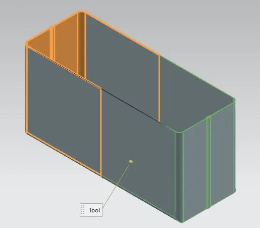
- Unite : It is used to combine different bodies together.
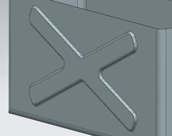
- Dimple : It is used to lift an area of model inside the sketch that simulates a stamping tool.
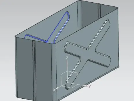
- Mirror Feature : It is used to mirror a feature along a line/plane.
- Dimple : It is used to lift an area of model inside the sketch that simulates a stamping tool.
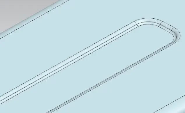
- Bead : It is used to lift material along contour of sketch that simulates the stamping tool.
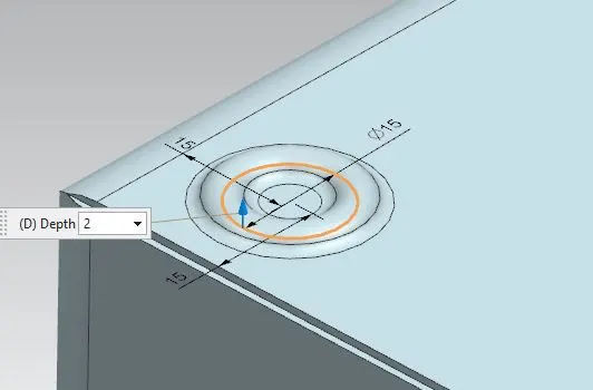
- Mirror Feature : It is used to mirror a feature along a line/plane.
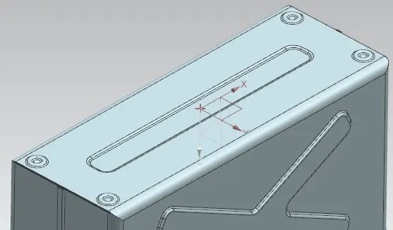
- Hem Flange : This adds an overlapping edge to an existing flange itselt in order to increase edge stiffness or for safe handling.
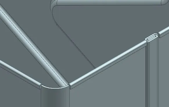
- Tab : This is used to create a base by extruding a sketch in particular direction or simple adds material to a sketch giving thickness.
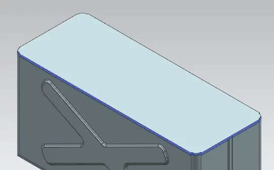
- Flange : It adds a flat flange with an angle to a plane surface and adds a bend in between two.
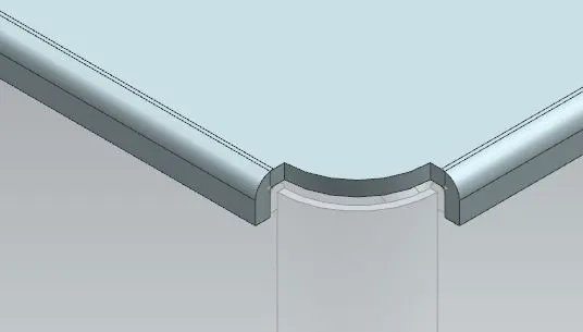
- Tab : This is used to create a base by extruding a sketch in particular direction or simple adds material to a sketch giving thickness.
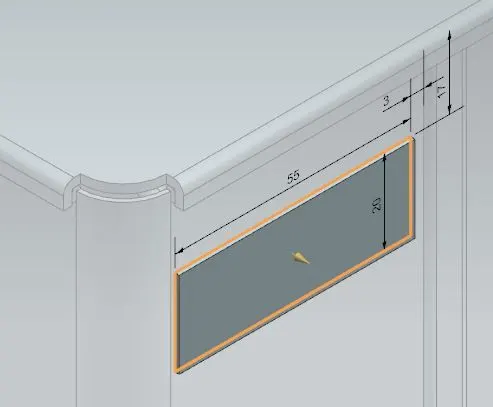
- Break Corner : It adds a round shape or chamfer to sharp corners of the model.
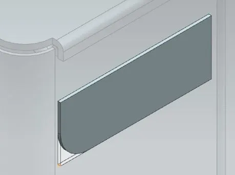
- Flange : It adds a flat flange with an angle to a plane surface and adds a bend in between two.
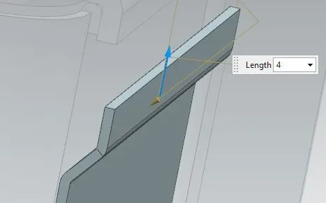
- Hem Flange : This adds an overlapping edge to an existing flange itselt in order to increase edge stiffness or for safe handling.
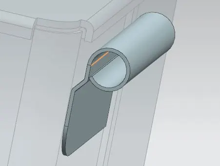
- Unbend : It is used to flatten the bends along with the material adjacent to it.
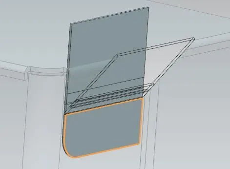
- Normal Cut : This is used to eliminate material from a model that intersects with the proection of a sketch.
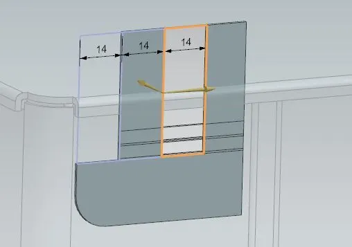
- Rebend : This is used to restore the flattened bends and material adjacent to actual position they were before, along with the features added after unbending.
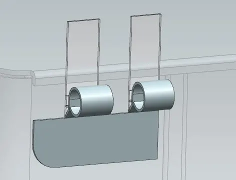
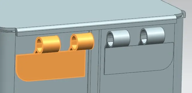
- Mirror Body : It is used to mirror a body along a line/plane.
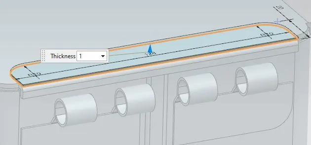
- Tab : This is used to create a base by extruding a sketch in particular direction or simple adds material to a sketch giving thickness.
- Flange : It adds a flat flange with an angle to a plane surface and adds a bend in between two.
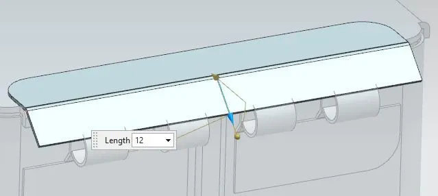
- Hem Flange : This adds an overlapping edge to an existing flange itselt in order to increase edge stiffness or for safe handling.
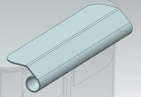
- Unbend : It is used to flatten the bends along with the material adjacent to it.
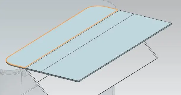
- Normal Cut : This is used to eliminate material from a model that intersects with the proection of a sketch.
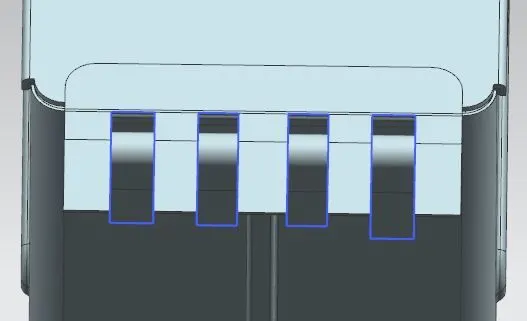
- Rebend : This is used to restore the flattened bends and material adjacent to actual position they were before, along with the features added after unbending.
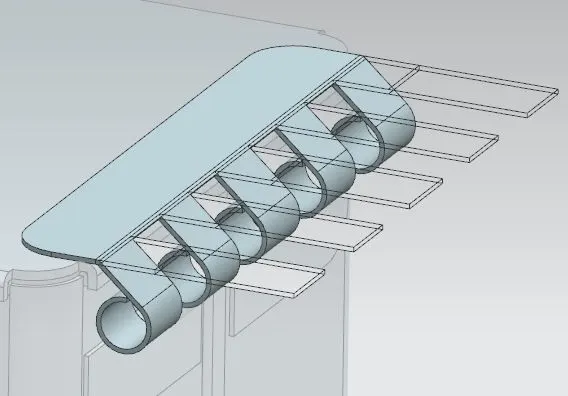
- Flat Pattern : This creates a flat pattern in 2-D from the final sheet metal model.
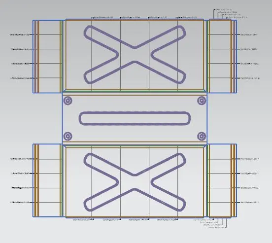
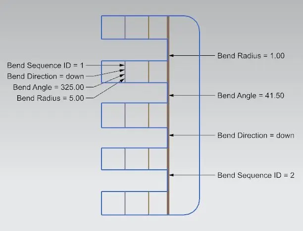
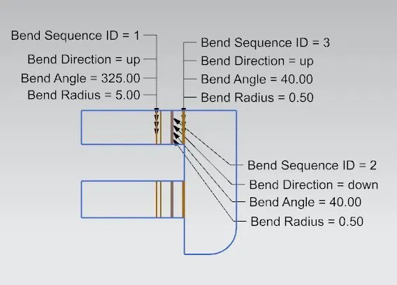
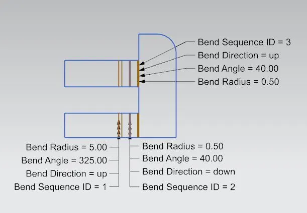
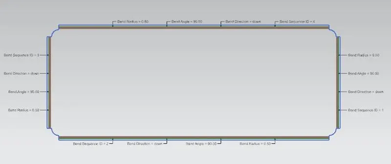
- Drafting : It is used to plot a drawing of final sheet metal model with desired orientatioin.
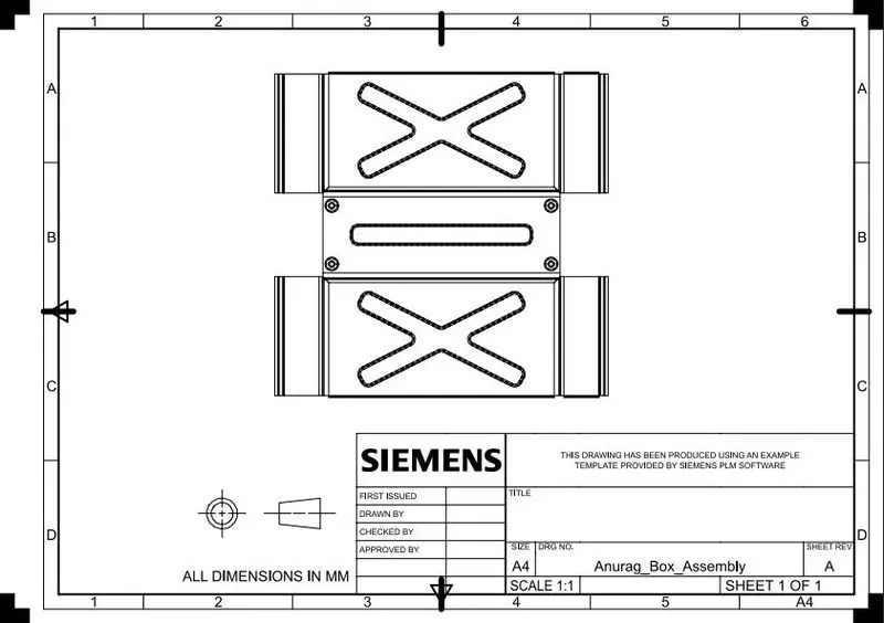
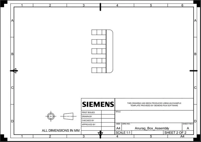
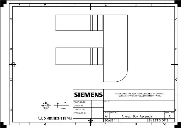
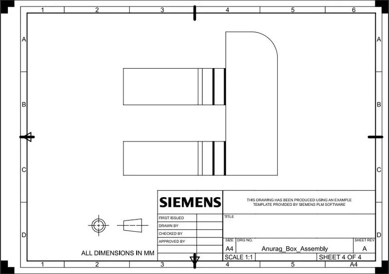
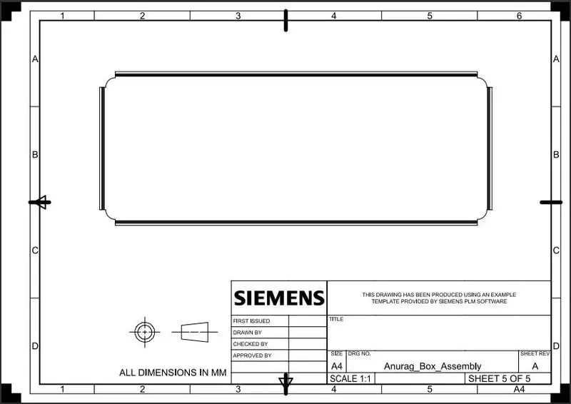
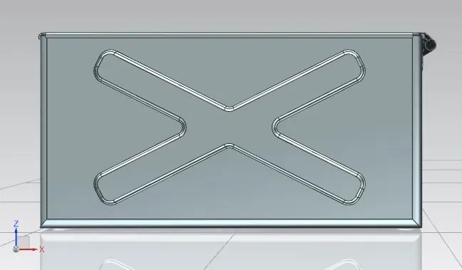
Front View
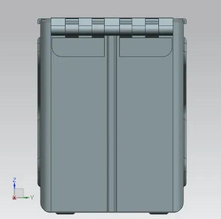
Side View
Top View
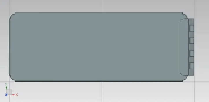
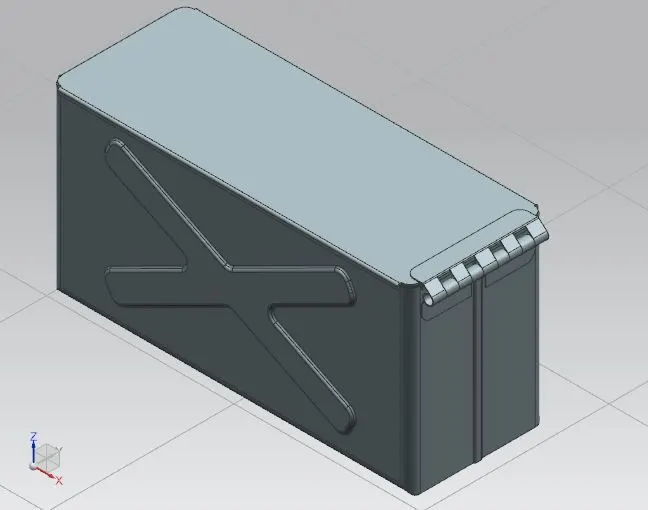
Isometric View
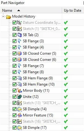
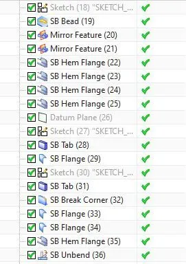
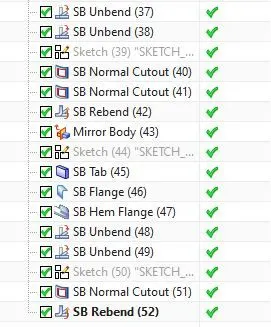
Feature Tree
Conclusion : By following the procedure, we were able to understand the working of features applied and could design a desired sheet metal model in NX-12.