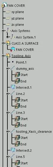
Week 8 - Challenge 1 - Draft Analysis on a Fan Cover
Draft Analysis : When a product is manufactured, whether it be sheet metal component or plastic part, the side walls or say the parallel walls along the reciprocating direction of machine, are tend to get rubbed against the machine tools or cavity block. This rubbing during the ejection of component can reduce the surface finish or damage the part. To neglect this damage and easy removal of part, these parallel walls are given a tilt with minimal angle and is referred as draft angle. During designing the part, draft analysis is done to get ensure about the manufacturability of that part.
Here, we will discuss the process by taking an example of plastic Fan cover. Below shown is a Class A surface given as an input. First of all, check whether the surfaces are joined together and no gap is left within them. We can check this by Join operation or by examining the open boundaries of it.
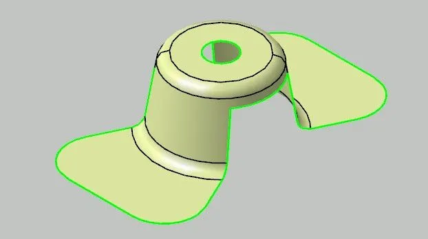
Then, have a look at the entire part and decide where can be the tooling axis. Seeing a hole in centre region, it is feasible to take it in main direction of core and cavity and so can neglect side core also. Add a point and axis system at centre.
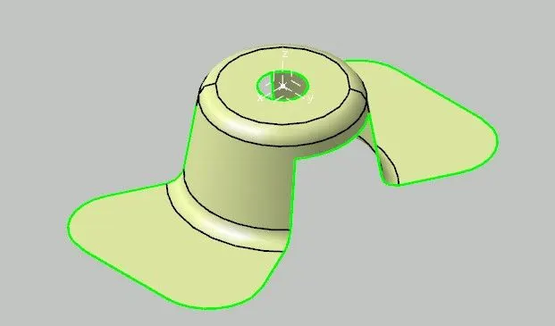
Create a line normal to it which will act as a dummy tooling axis for now. This is not the final tooling axis. By seeing at the component, we are just assuming it to be.
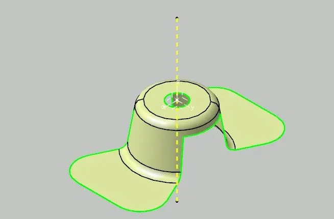
After that, look for the walls that are along the tooling axis direction. For them, take intersection of those walls along the plane and you get a profile. Extend lines over that wall profiles and create a line bisecting them. This can be referred as clearance tooling axis in X-direction.
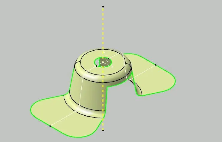
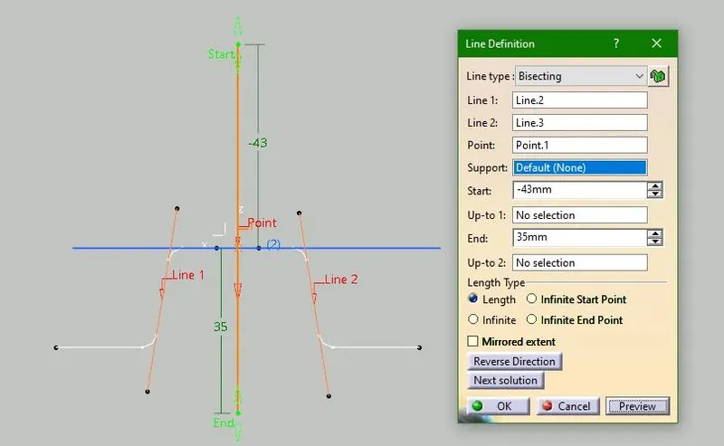
Do the same process for another plane too and create a clearance tooling axis for Y-direction.
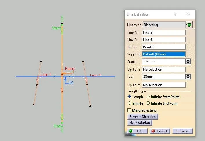
After creating two clearance axes, bisect them and create a line and it will be the final tooling axis. As we were not sure about the symmetricity of the component, for precision we took two clearance axes for two different planes.
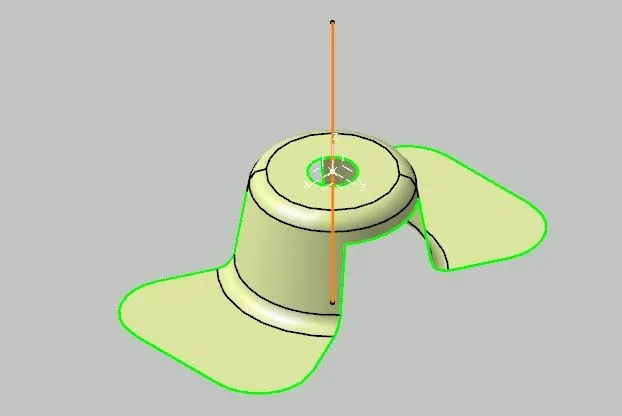
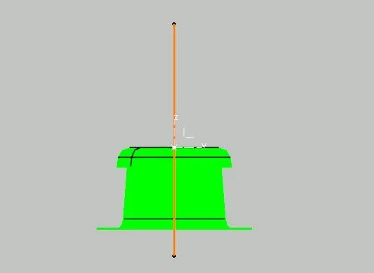
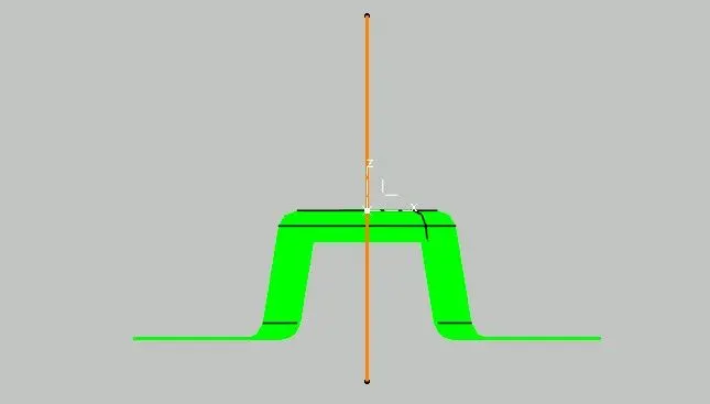
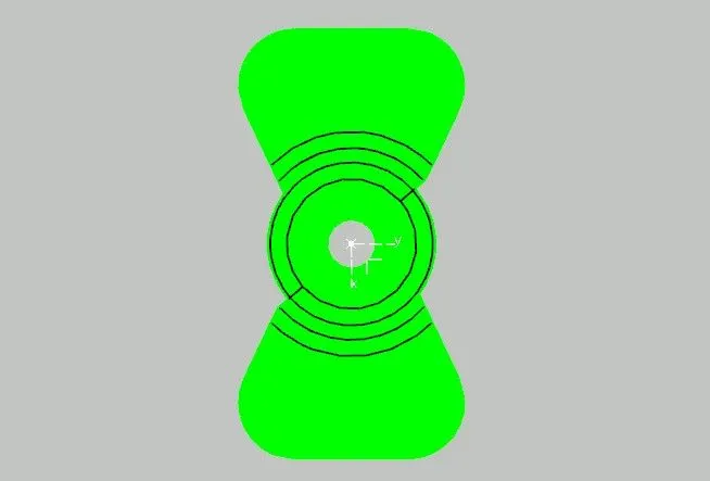
Next step is to analyze the part and check if the created tooling axis is correct or not and makes the component manufacfacturble. For this, under analysis pick draft analysis. One pop-up will be the colour code where we can set different colours according to our need. Here, we want minimum draft angle to be 3 degrees. In another pop-up we will pick orientation and drag and drop the compass along the tooling axis. Lock it and pick the component and it will show the results. Here, we got the green surface, that means it passed the draft analysis and the tooling axis is correct and also part is manufacturable.
Other colours shows incorrectness.

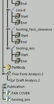
Tree Structure