Advanced Sheet Metal Design Using NX Cad Challenge_6_Bracket
DESIGNING A BRACKET IN NX
The Objective of this project is to design a metal sheet bracket in Siemens NX-12 and learn about the tools and features from NX.
INTRODUCTION : In this project, we will see a step by step procedure of creating a bracket in Siemens NX-12. All the features used during the creation are briefly explained. We will learn about them and see how to use them too.
The Approach towards the creation of model is shown through a flow chart :
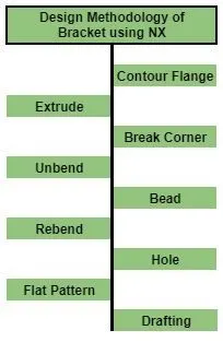
DESCRIPTION : The features used step by step during the procedure of designing are as under :
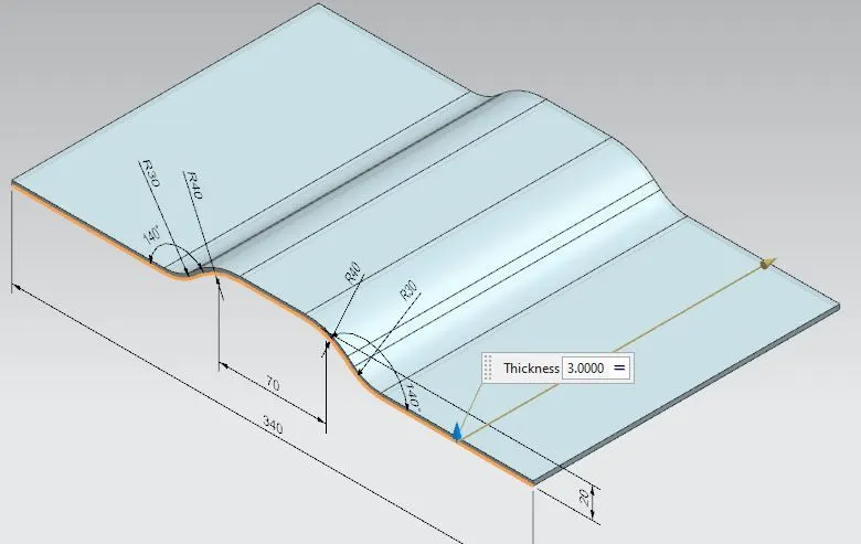
- Base Contour Flange : This is used to create a base sheet from a contour of sketch or simply extrudes an edge of a sketch along a vector.
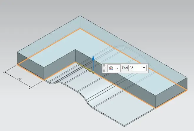
- Extrude : It thickens a sketch profile by adding material to it, along a vector. Here this feature is used to intersect the extruded part with an existing part and eliminating the rest part.
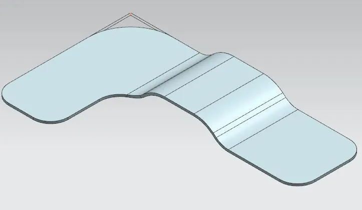
- Break Corner : This is used to convert sharp edges of model into round faces/fillet for given radius.
- Unbend : It flattens the bend of a work along with the adjacent faces and gives a planar face.
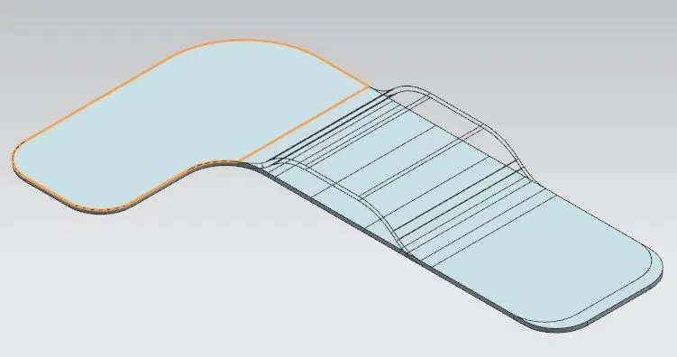
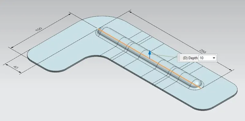
- Bead : This feature is used to raise material along the contour of sketch that simulates the stamping tool.
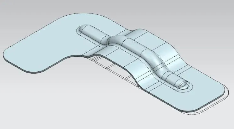
- Rebend : It recovers flatenned bends along with adjacent faces to its earlier position, along with the features added to it after unbending.
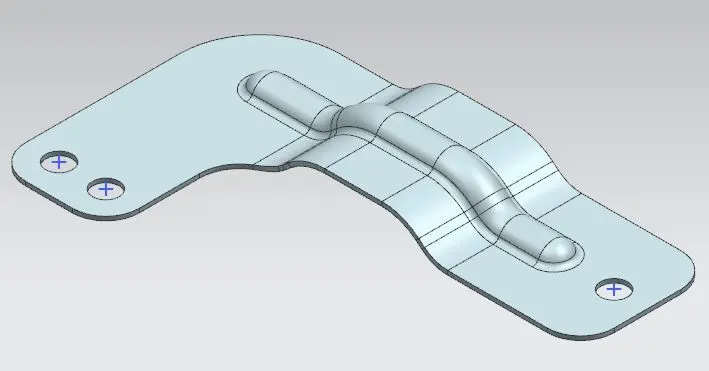
- Hole : This is used to add holes of specific diameter into a work model.
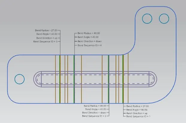
- Flat Pattern : This is used to create a flat pattern of the final model with all the necessary design parameters.
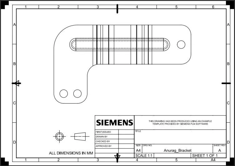
- Drafting : It is used to create a 2D drawing of the final model with proper orientation.
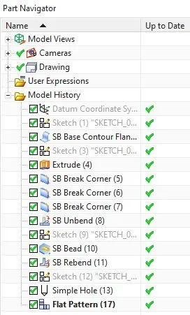
Feature Tree
Front View
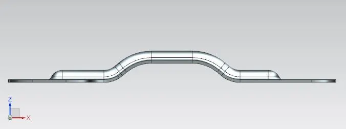
Side View
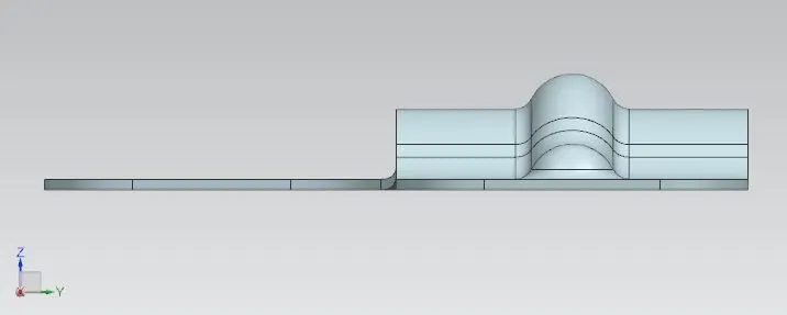
Top View
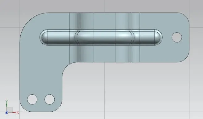
Isometric View
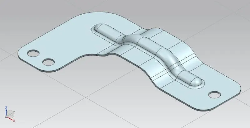
CONCLUSION : By following the procedure, we learnt about the features used and accurately designed a sheet metal bracket in Siemens NX.