To create Class B surface, Class C surface and attachment features of B Pillar From Master section
AIM: To create Class B surface, Class C surface and attachment features of B Pillar From Master section.
Introduction:
B Pillar-
B Pillar is the most complex component/structure of the vehicle body. This is because the front door closes on the B pillar while the rear door hinges onto it. The B pillar or the center pillar in vehicles is made of steel. It is welded to roof panel on top and the vehicle’s floor pan at the bottom. This pillar provides structural support to the vehicle’s roof.
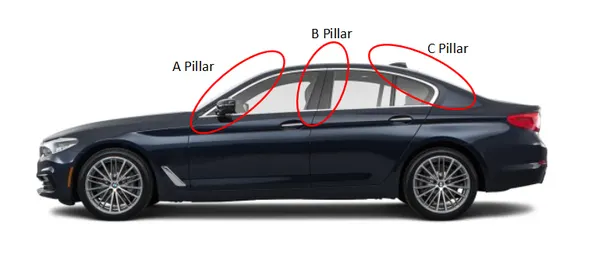
Manufacturers skip the B pillar while naming other pillars. Hence, some vehicles do not have a B Pillar. The carmakers term those cars as 'Hardtops.' Instead, the vehicle specification shows the rearmost pillar as the C pillar. The manufacturers offer the Hardtops in nearly all four-door body styles. They include sedans, coupes, and wagons/MPVs. The cars without B pillars increase passenger’s visibility. However, they have limited structural support and strength. General Motors later started providing B pillars in Hardtops. Thus, it created a new vehicle body type and thereby broadened the definition of Hardtops.
Master Section-
There are the guidelines provided to a design engineer which describe how a component would/must look like once it is modeled into a solid component from the class A surface.
PROCEDURE:
Create tooling axis:
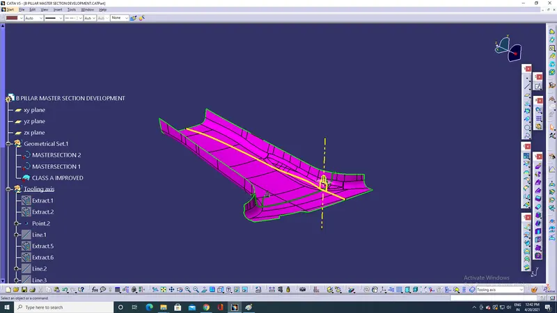
Tooling direction is the direction in which mold opens or Core and Cavity opens.
- To create the tooling axis, we need proper orientation or view thatgives the correct featues and draft available in the component.
- So here the component view from the Z direction gives the proper view for the tool to see the features present in the geometry.
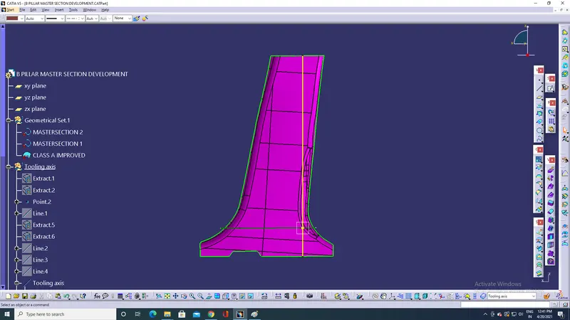
- To create the tooling axis from the Z direction we need the tooling axis from the other X direction since it gives the draft available at the slanted part.
- In B pillar model there are two tooling directions one on the main tooling and other on lifter side that is used to eject the parts during injection mlding. Lifter axis is used because he attachment feature is bounded by close walls.
- Tooling axis is created by using Bisecting method.
Draft Analysis:
Draft : Drafts are defined on molded parts to make them easier to remove from mold.
Drafting methods:
- By explicitly selecting the object.
- By selecting the neutral element
Major industries uses minimum draft angle of 3mm.
- Change the shading style to "shading with material".
- Go to insert>analysis>Feature draft analysis.
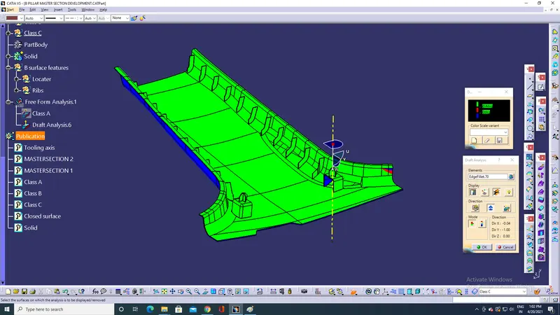
- Select compass icon in draft analysis dialogue box and drag the compass and place it on tooling axis and select lock draft direction option.
- Swith to quick analysis mode to see whether the surfaces are passed draft angles or not.
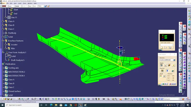
As can see some portion is not clearing for draft analysis so there is a need of changes in class A surface.
Create Class B surface
- Class B surface was created from the class A surface using Extract or MultiExtract option.
- Flanges are created according to master section.
- Class B surface was offseted at a distance of 2.5mm thickness from the class A surface.
- Fillets were applied after necessary calculations.
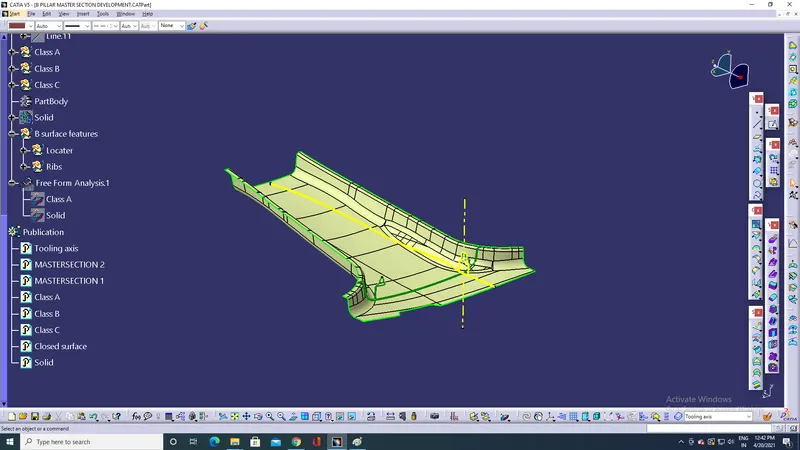
Fig: Class B surface
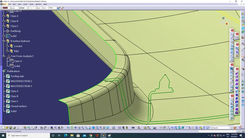
Fig: Flange created on class B surface as per master section.
Create Class C surface
- Class C surface was swept along the boundary of Class A using Sweep option at an angle normal to the class A surface with respect to the tooling axis.
- A nominal draft angle of 3 degrees was applied.
- The Class C surface joined along withhe class A surface.
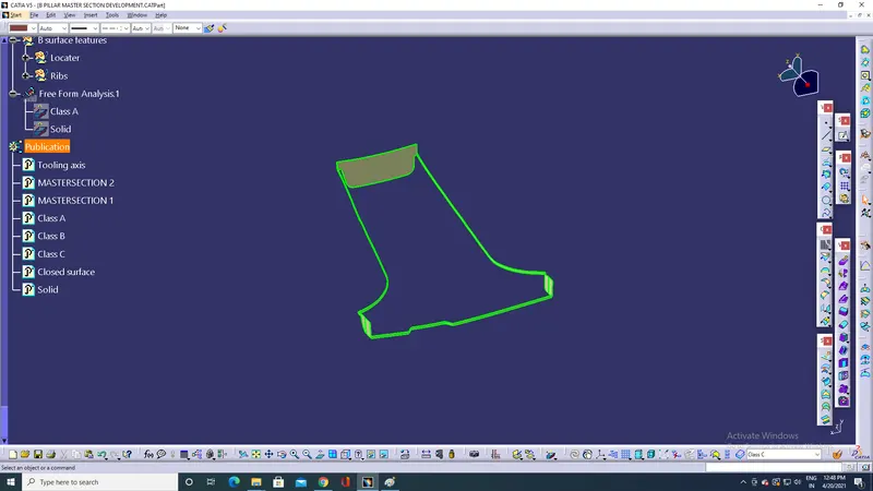
Create a closed surface
- Class A, B and C surfaces were joined together to form a single closed surface.
- Trim the Class B surface with the joined Class A and C surface to get closed surface.
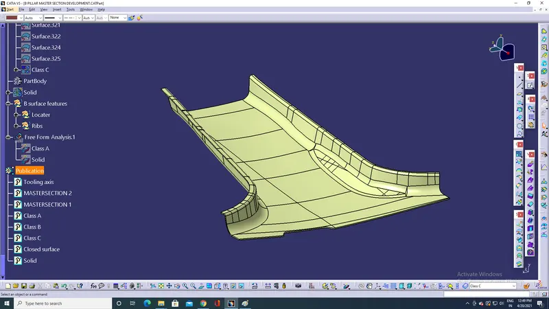
Create a solid part from closed surface
Insert a part body and create a solid part using closed in part workbench.
Attachment features:
- Doghouse with screw boss:
General Guidelines for Bosses:
- Draft - 0.5 degrees on walls of boss
- Thickness - Typically 40%* of the nominal wall at the base.
- Height to Diameter Ratio - 3:1
- Radii - 0.25mm maximum radii.
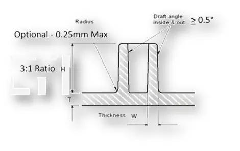
- General Guidelines for Doghouse:
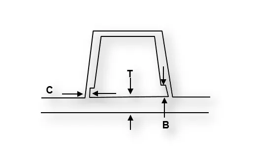
-
"C" is where the doghouse contacts the backside of the surface.
-
Doghouse wall thickness at the intersection of the part wall ( C ) should be 40% or less than the main wall stock ( T ).
-
Height of ( B ) should be between 3.0 – 6.0 mm
Procedure:
- Lines are extracted from the master section.
- Surfaces are created using extracted line.
- By using offset and trim option closed surface is ceated.
- Closed surface is converted into solid part.
- Draft angle of 0.5deg and fillet radius of 0.25mm is provided at all surfaces.
- Copy and mirror option is used to create another doghouse.
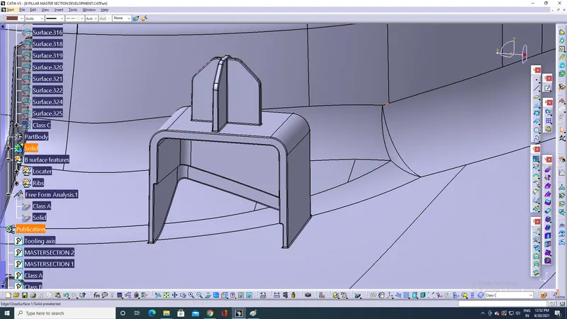
Fig: Doghouse
Draft analysis:
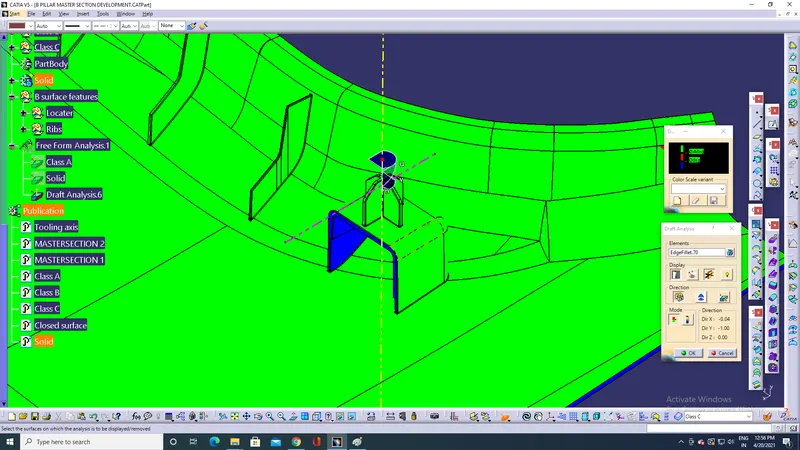
Fig: Draft analysis of doghouse(main tooling axis)
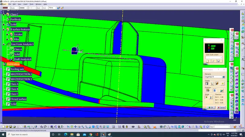
Fig: Draft analysis of doghouse(side core tooling axis)
- Ribs:
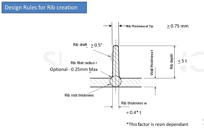
Procedure:
- Using Position sketch on this surface draw a line.
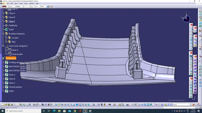
- Extract surface out of the line using 'Extract' option. Height of the rib to be maintained as 5 times the thickness of the component. The thickness of the component is 2.5mm so extrude the line up to 12.5mm.
- Convert the surface into solid by using 'thick' option in part workbench.
- The distance between the two ribs must be 50mm.
- Draft angle of 0.5deg and fillet radius of 0.25mm is provided at all surfaces.
- Copy and translate option can be used to create another rib.
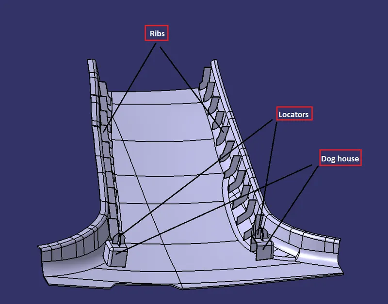
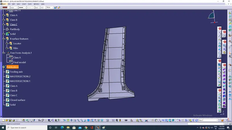
Final Model:
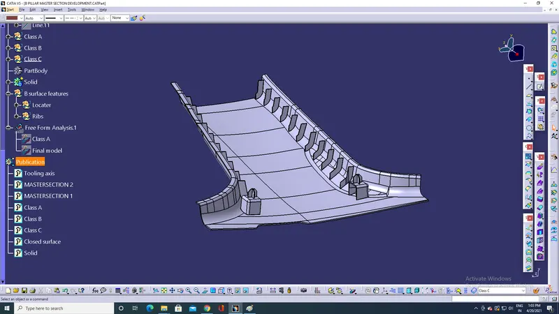
Draft analysis of final model:
CONCLUSION:
- Tooling axis created for the Class A surface of B pillar and draft analysis is perfomed for the same.
- Created Class B and Class C surface. Class A,B and C surface is joined to get closed surface and converted into solid part.
- Created Attachment features from master section.