Week 11 - Final project
AIM: To create Class B surface, Class C surface and attachement features for Door Trim Panel from master section.
SUMMARY:
Product life cycle in the automotive industry
Product life cycle is the process which involves forming strategy, organizing requirements, generating concepts, creating product & marketing plan, evaluating and subsequent commercialization, thereby bringing a new product to the marketplace. It involves-
- Concept sketch
- Styling Class A
- Feasibility Check
- Concept validation
- New product design
- product development
- Pototype build
- Design validation
- Pilot production
- Mass production
New Product design (NPD) CAD:
Every product you have in your home and interact with is the outcome of a design procedure. All those products have come into being after long hours of planning, sketching, rendering, 3D modeling. Not to mention the numerous prototypes and testing it has gone through to finally hit the shelves.
New product Design is the professional practice of conceptualizing and designing products, which are to be manufactured through techniques of mass production, eventually to be used by millions of people around the world every day.
An industrial product design process incorporates inputs from diverse domains such as ergonomics, form studies, studio skills, advanced cad, research methods, design management, materials & manufacturing processes and social sciences.
An industrial designer’s purpose is to emphasize on — appearance of a product, the functioning, how the product is manufactured and the value & experience it provides for users. Their sole intent is aimed at improving your life through design.
Door arm trim:
The door trim panel is the inerior plastic component attached to the sheet metal part of the door. It is designed differently based on the design of the sheet metal part of the door. Besides its aesthetic look, it also has many functional features attached to it such as an armrest, bottlr holder, speaker attachment, etc.
Maser section
There are the guidelines provided to a design engineer which describe how a component would/must look like once it is modeled into a solid component from the class A surface.
PROCEDURE:
1.Create the Tooling axis
Tooling direction is the direction in which mold opens or Core and Cavity opens.
- To create the tooling axis, we need proper orientation or view thatgives the correct featues and draft available in the component.
Procedure:
- Go to insert>analysis>Feature draft analysis.
- Select compass icon in draft analysis dialogue box and drag the compass and place it on class A surface
- Change the compass direction till all the surface of this portion passes for given draft angle.
- Lock the Compass direction.
- Go to 'lines'>select point and direction>select the point and direction as compass direction.
2.Draft Analysis:
Draft : Drafts are defined on molded parts to make them easier to remove from mold.
Major industries uses minimum draft angle of 3mm.
- Change the shading style to "shading with material".
- Go to insert>analysis>Feature draft analysis.
- Select compass icon in draft analysis dialogue box and drag the compass and place it on tooling axis and select lock draft direction option.
- Swith to quick analysis mode to see whether the surfaces are passed draft angles or not.
1.Door arm rest
- Upper part
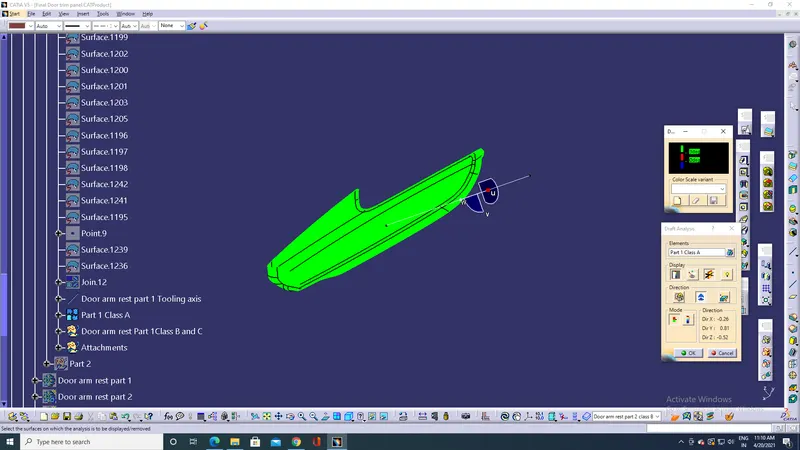
- Lower part
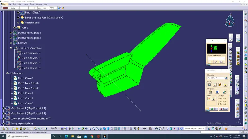
2.Upper map pocket
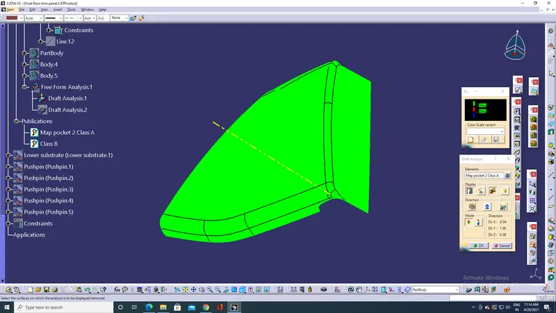
3.Lower map pocket
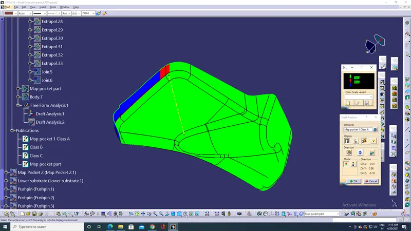
4.Lower substrate
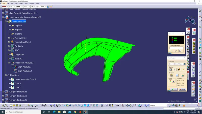
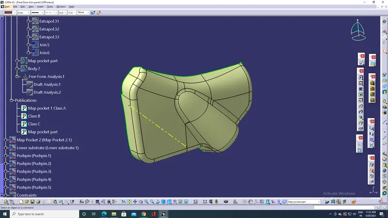
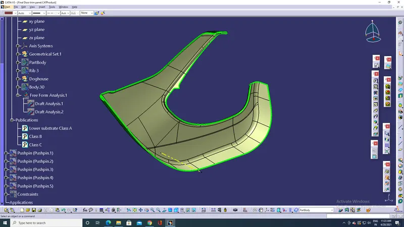
3.Create Class B surface
- Class B surface was created from the class A surface using Extract or MultiExtract option.
- Class B surface was offseted at a distance of master section thickness from the class A surface.
- Fillets were applied after necessary calculations.
1.Door arm rest
- Upper part
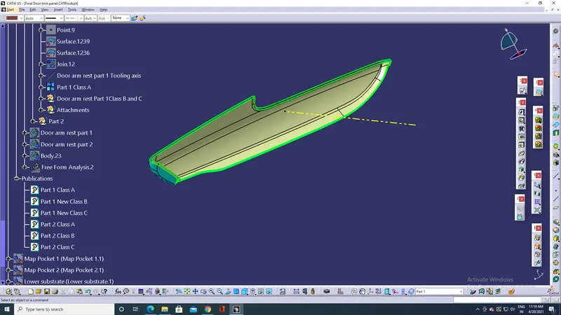
- Lower part
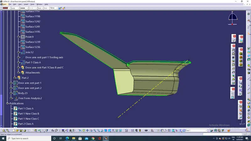
2.Upper map pocket
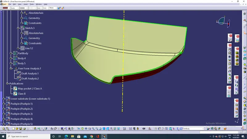
3.Lower map pocket
4.Lower substrate
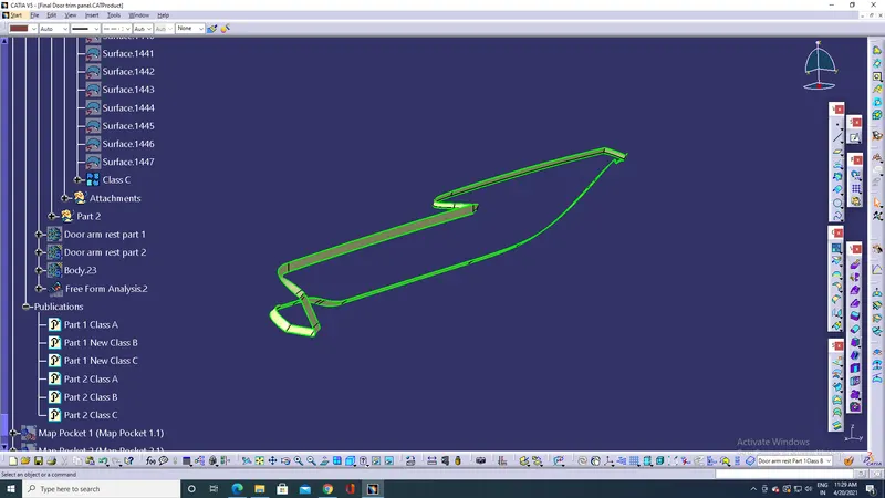
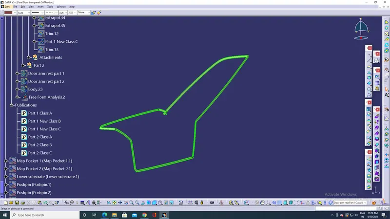
4.Create Class C surface
- Class C surface was swept along the boundary of Class A using Sweep option at an angle normal to the class A surface with respect to the tooling axis.
- A nominal draft angle of 3 degrees was applied.
- The Class C surface joined along with the class A surface.
1.Door arm rest
- Upper part
- Lower part
2.Upper map pocket
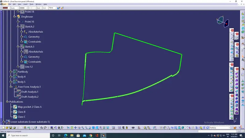
3.Lower map pocket
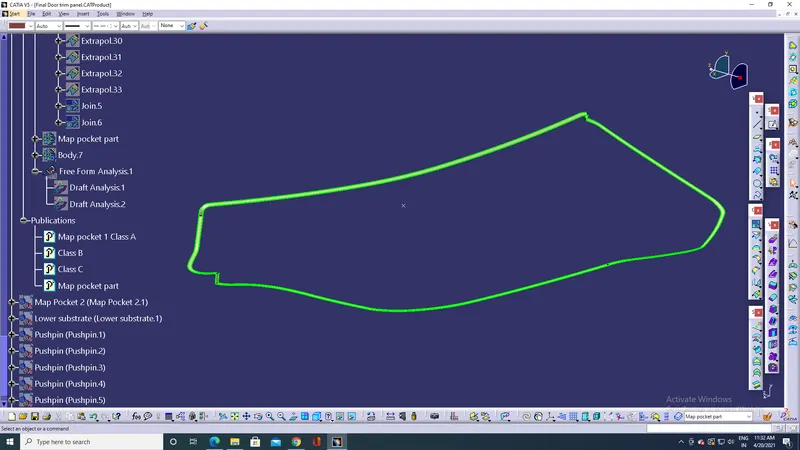
4.Lower substrate
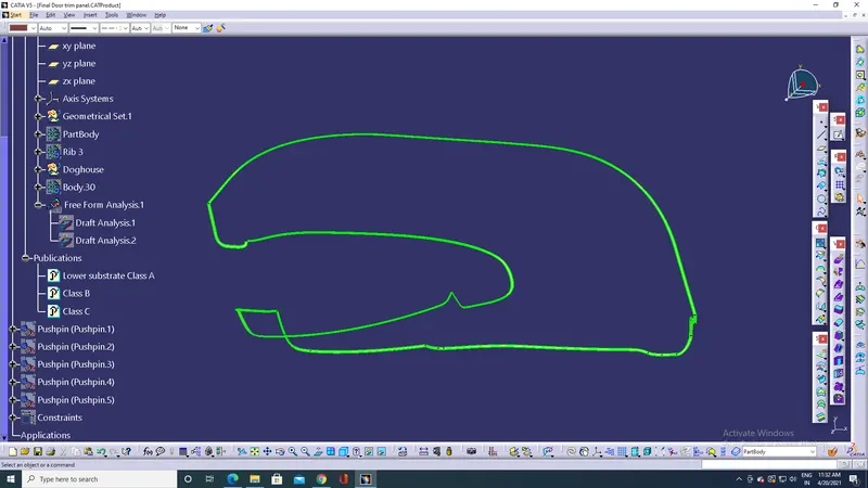
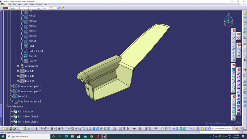
5.Create a closed surface
- Class A, B and C surfaces were joined together to form a single closed surface.
- Trim the Class B surface with the joined Class A and C surface to get closed surface.
1.Door arm rest
- Upper part
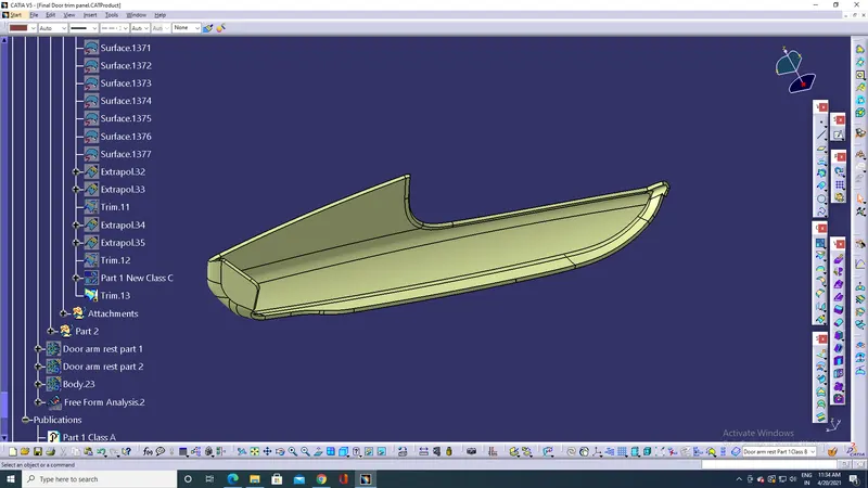
- Lower part
2.Upper map pocket
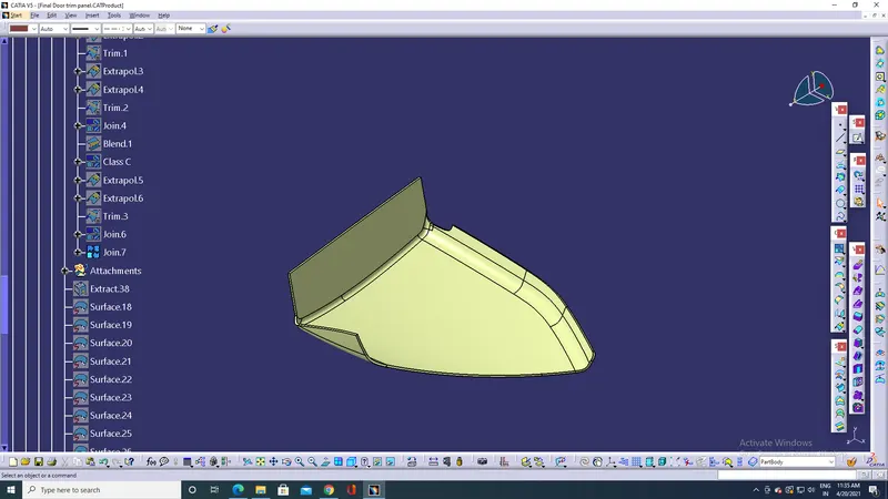
3.Lower map pocket
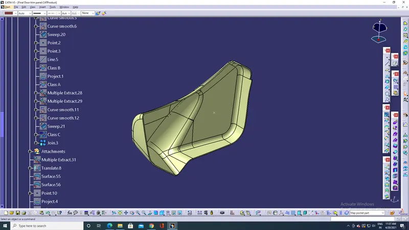
4.Lower substrate
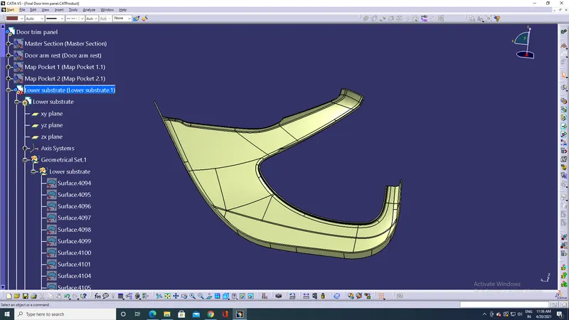
6.Create solid part
Convert closed surface into solid part by using closed option in part workbench.
1.Door arm rest
- Upper part
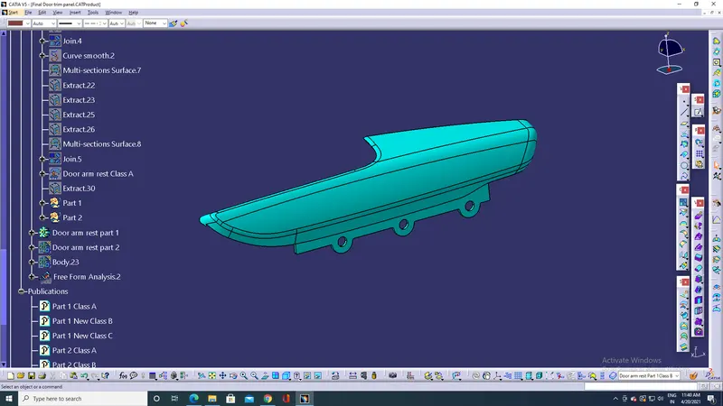
- Lower part
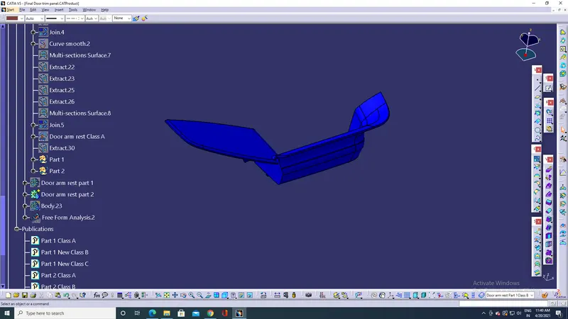
2.Upper map pocket
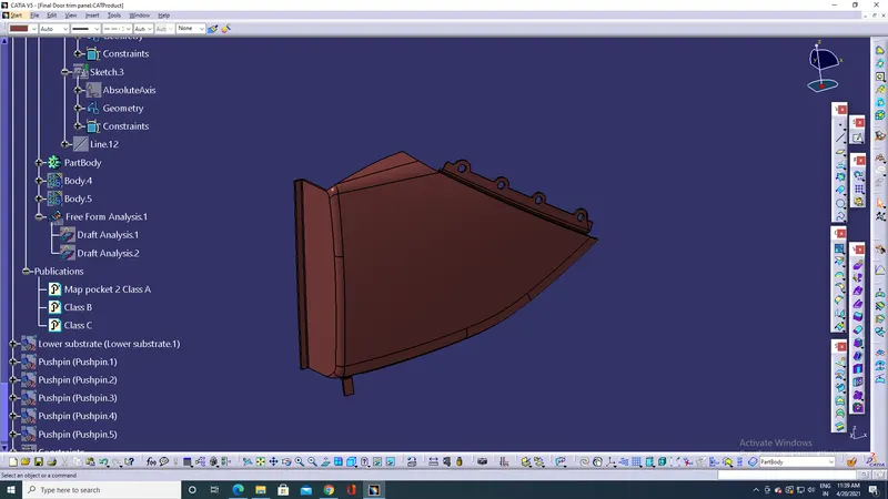
3.Lower map pocket
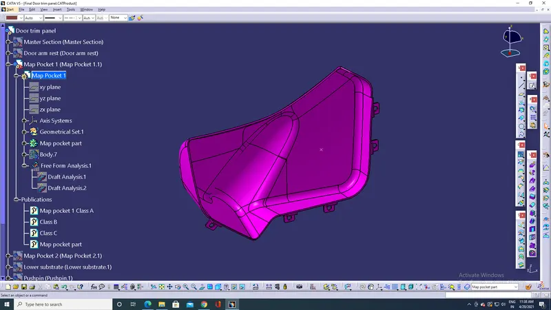
4.Lower substrate
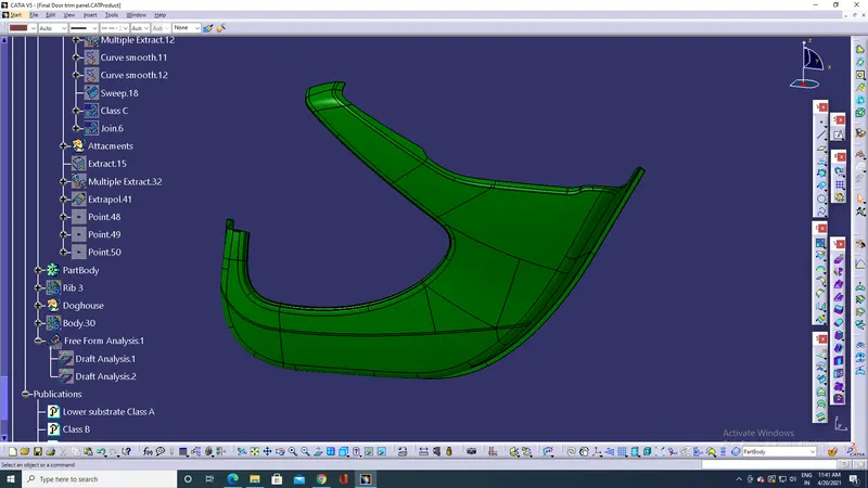
7.Attacment features:
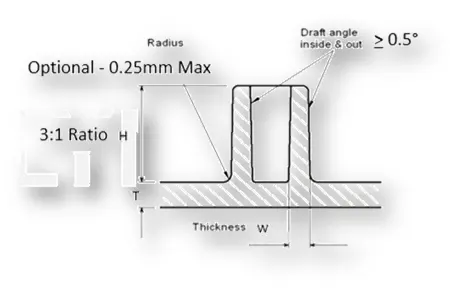
General Guidelines for Bosses:
- Draft - 0.5 degrees on walls of boss
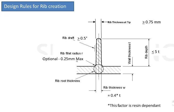
- Thickness - Typically 40%* of the nominal wall at the base.
- Height to Diameter Ratio - 3:1
- Radii - 0.25mm maximum radii.
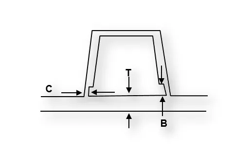
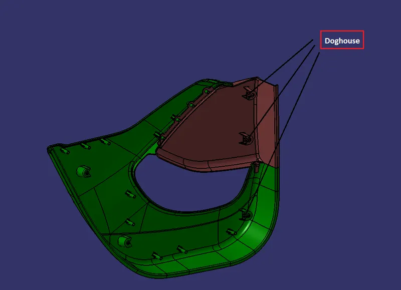
General Guidelines for Doghouse:
-
"C" is where the doghouse contacts the backside of the surface.
-
Doghouse wall thickness at the intersection of the part wall ( C ) should be 40% or less than the main wall stock ( T ).
-
Height of ( B ) should be between 3.0 – 6.0 mm
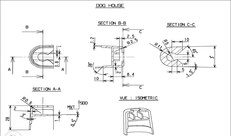
Procedure:
- Lines are extracted from the master section.
- Surfaces are created using extracted line.
- By using offset and trim option closed surface is ceated.
- Closed surface is converted into solid part.
- Draft angle of 0.5deg and fillet radius of 0.25mm is provided at all surfaces.
- Copy and mirror option is used to create another doghouse.
"Add pic of Doghouse"
Ribs:
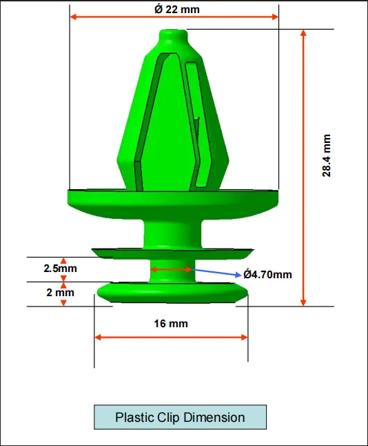
Create Locators and Pushpins:
- Create a locators and Pushpins as per given dimensions
- Give draft angle of 0.5 deg and fillet of radius 0.25mm for all the surfaces.
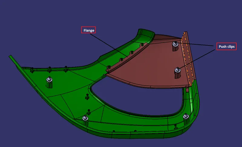
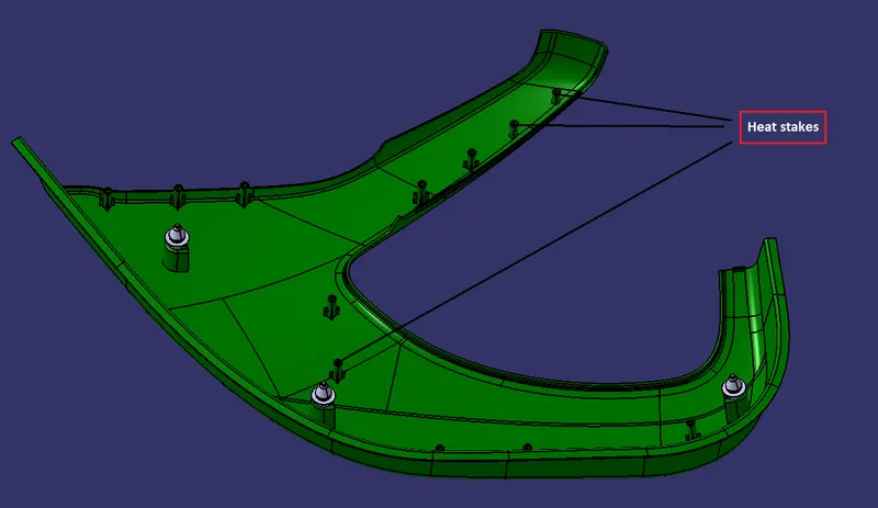
Create Heat stakes:
- Create a heat stake sketch on the Class B side of the solid part using positioned sketch and pad it.
- The clearence between the heat stake and hole is 0.5mm.
- Give draft angle of 0.5 deg and fillet of radius 0.25mm for all the surfaces.
- Use Copy and translate option to create more heat stakes.
8. Draft analysis of finished model
1.Door arm rest
- Upper part
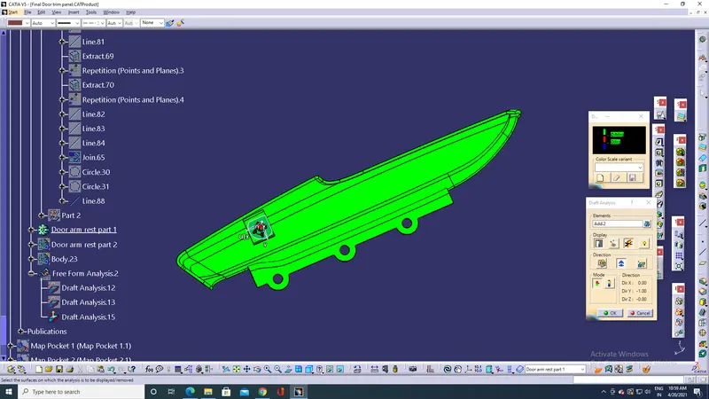
- Lower part
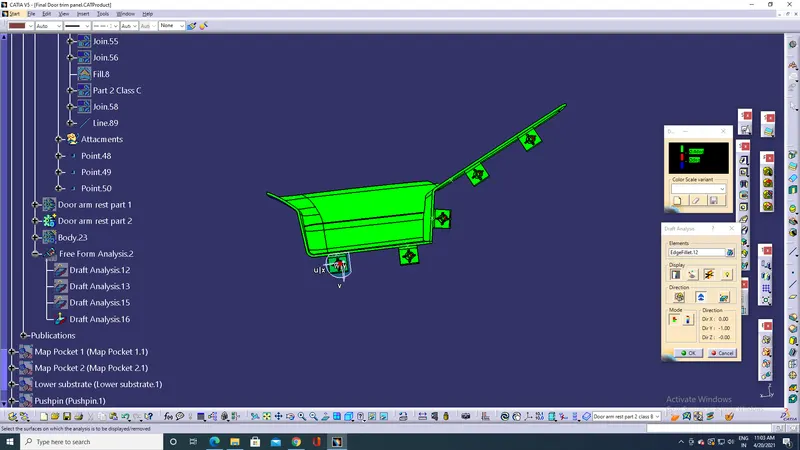
2.Upper map pocket
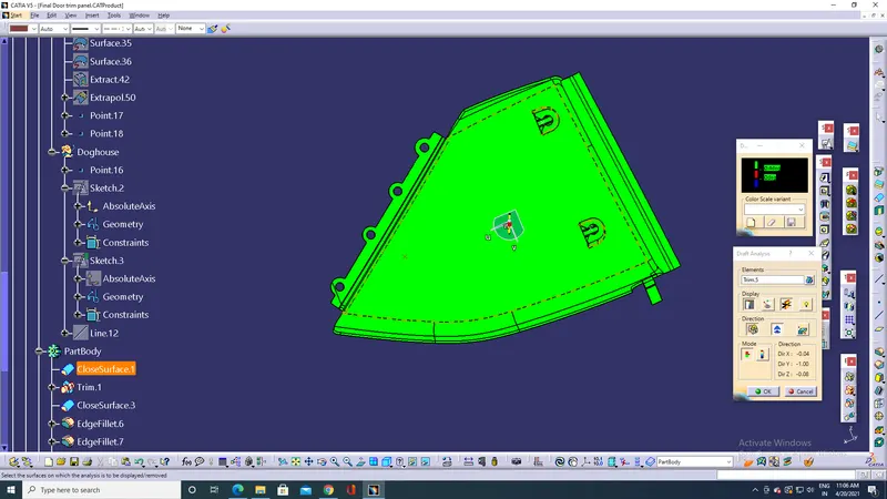
3.Lower map pocket
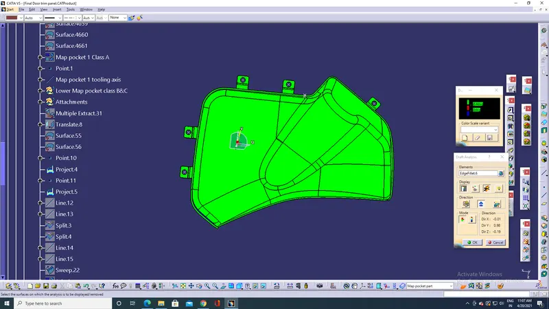
4.Lower substrate
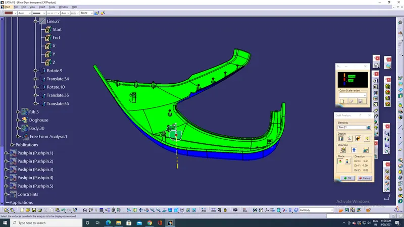
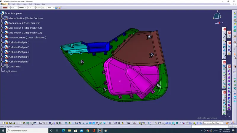
Final model
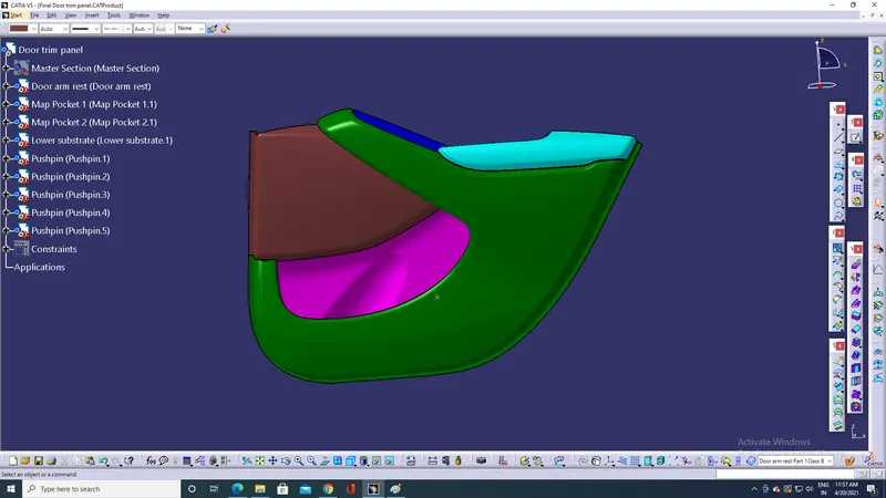
Inner side:
Outer side:
CONCLUSION:
- Created thickened part using master section reference.
- Created the mounting features as per design guidelines in the industry and with master section.
- Performed Draft analysis & Tooling analysis.
- Created of parting lines and checked tooling feasibility.