Full Frontal Crash Analysis of Dodge NEON BIW car model as per FMVSS standards
AIM: To setup the case for frontal crash BIW of car and run the simulation.
OBJECTIVE:
- Check unit system and either follow[Mg mm s] or [Kg mm ms].
- Create appropriate interface ,friction 0.2 and recommended parameters.
- Make sure of no penetrations and intersection.
- Correct rigid bodies if any issues.
- Create rigid wall with friction 0.1.
- Compare the model weight with the full scale 300k nodes model and use added masses to reach target weight 700kg while getting CG about the required range.
- Initial velocity 35 mph.
- Use model checker to ensure good quality.
- Time-step :0.5 to 0.1 microseconds.
- Run 80 ms.
Output requests:
- Sectional force in the rails at location of indicated node 174247.
- Axial force received on the rails from bumper.
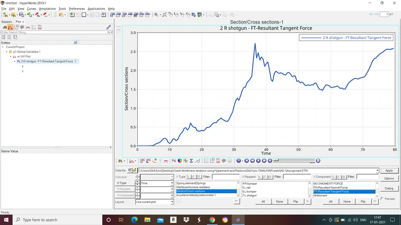
- Shotgun cross sectional forces.
- A pillar cross section.
- Acceleration curve received on the accelerometer at base of B pillar (on B pillar rocker).
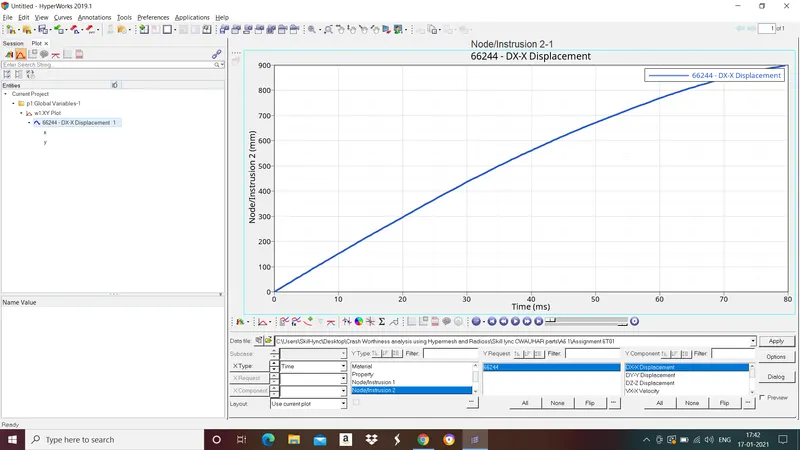
- Intrusions on the dash wall 66695,66244.
PROCEDURE:
- Import the Model:
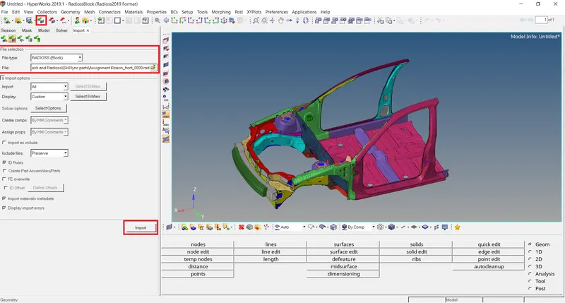
To import the model to Hypermesh goto file>import>solver deck>select the file>import.
- Check unit system:
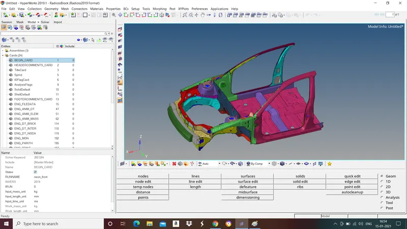
To check unit system go to model browser in tab bar>cards>BEGIN_CARD. In this Project we are following Kg,mm,ms.
- Create Interface and make sure of no intersections and penetrations:
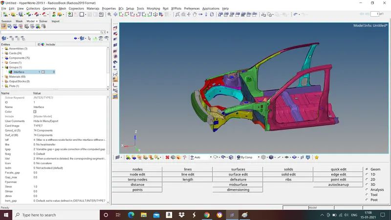
To create interface go to model browser in tab bar>right click select groups>in card image select "type 7" and select nodes and surface.
Recommended parameters for Type 7 interface.
Istf=4 (stifness of interface is based on softer of master and slave segments)
Igap=2 (Variable gap take into account)
Idel=2 (Remove slave nodes from contact because of element deletion)
Stmin=1000 N/mm (minimum stiffness between nodes and surface)
Gapmin=>0.5mm (minimum gap between nodes and surface)
Inacti=6 (gap is reduced and scaled)
Iform=2 (Sliding forces are computed using stifness parameters)
To check intersections and penetrations
Go to Tools>penetrations check>select the group>check.
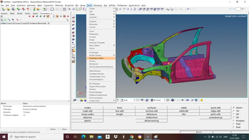
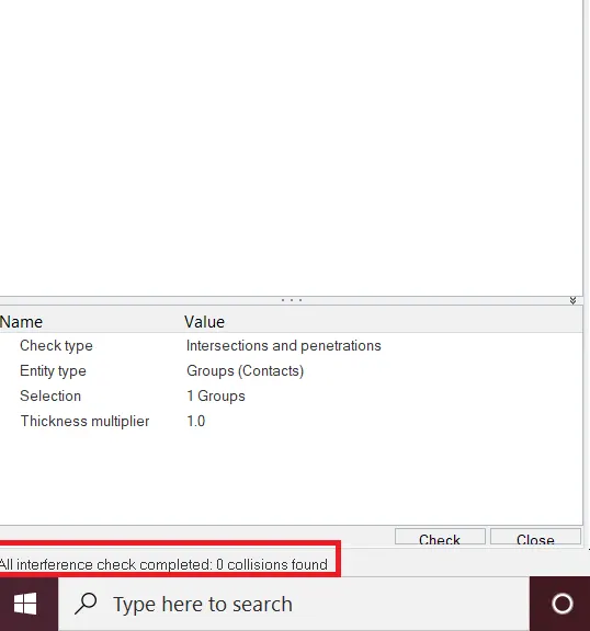
As we can see there are 0 penetrations and intersections found that means the model is free from penetrations and intersections.
- Create rigid wall with friction 0.1
To create rigid wall go to boundary conditions>create>Rigid walls.
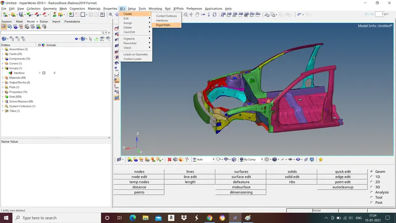
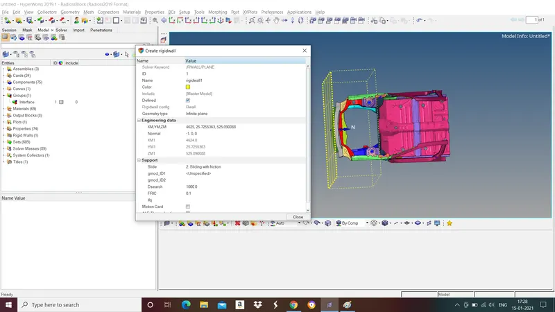
In rigid wall dialogue box select
- geometry type = Infinite plane
- Give XM,YM,ZM values
- Give normal values
- slide = sliding with friction
- FRIC = 0.1
- Dsearch = 1000
- Add masses to reach target weight 700kg while getting COG about the required range
The cog should be at the center of the body. To have cog at that position we need to balance the mass of the entire body.
To check the cog and mass of the body go to tools>mass details>mass,cog,inertia.
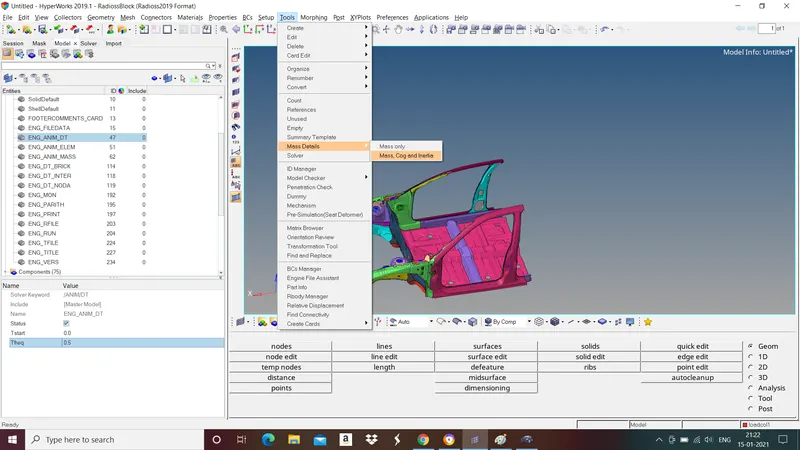
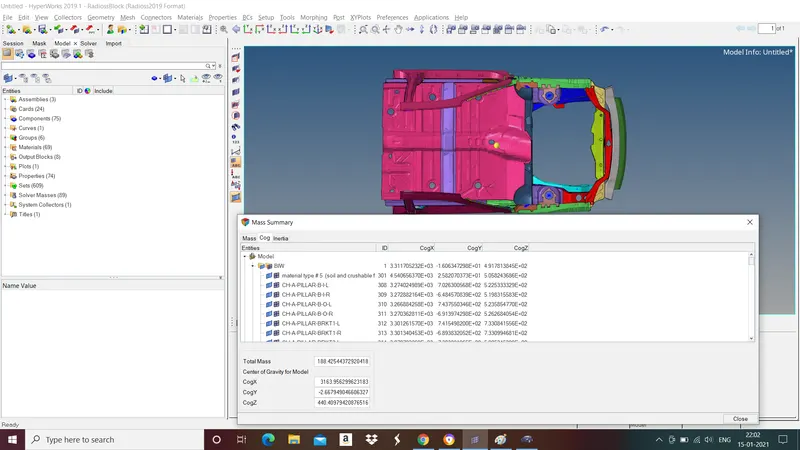
To know where is the cog in the model note down cogx,y and z value. Go to nodes>XYZ>give X,Y,and Z value.
Since cog is not at the center of the body add mass to the body to move the cog to required position.
To add mass goto model browser in tab bar>right click and select solvermass>select masstype 1(Mass/no. of nodes is added to the each node)>select nodes and mass.
Add mass to the bottom portion of the body beacause height of the cog is also matters in crash test of a car.
We got COG at the right position and also achieved target weight.
- Apply Initial velocity of 35 mph
To apply initial velocity go to model browser in tab bar>right click and select load collector>give velocity value and select the nodes.
Note:Convert given velocity units to required units i.e., mph to mm/ms.
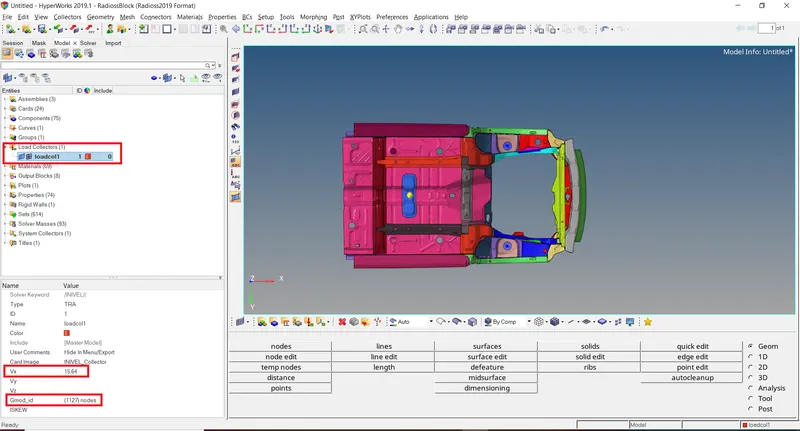
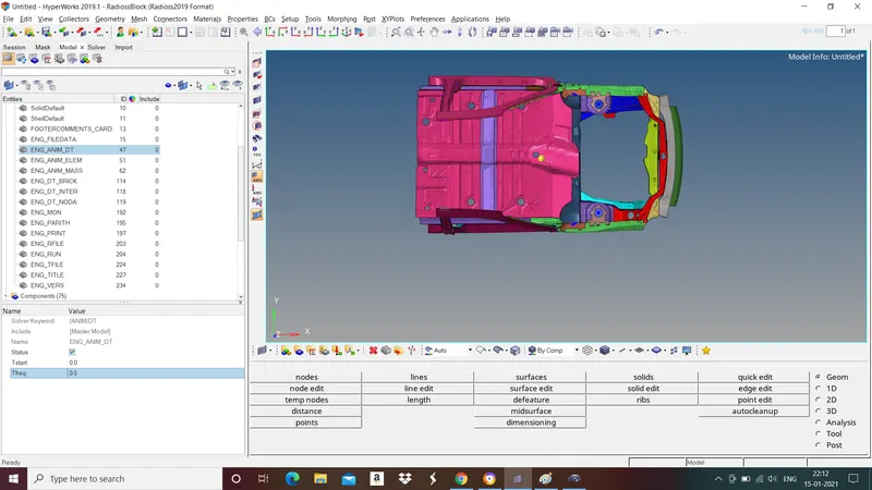
- Give time step of 0.5-0.1 microseconds and run for 80ms.
To give time step go to model browser in tab bar>cards>ENG_ANIM_DT>Give time step value in Tfreq.
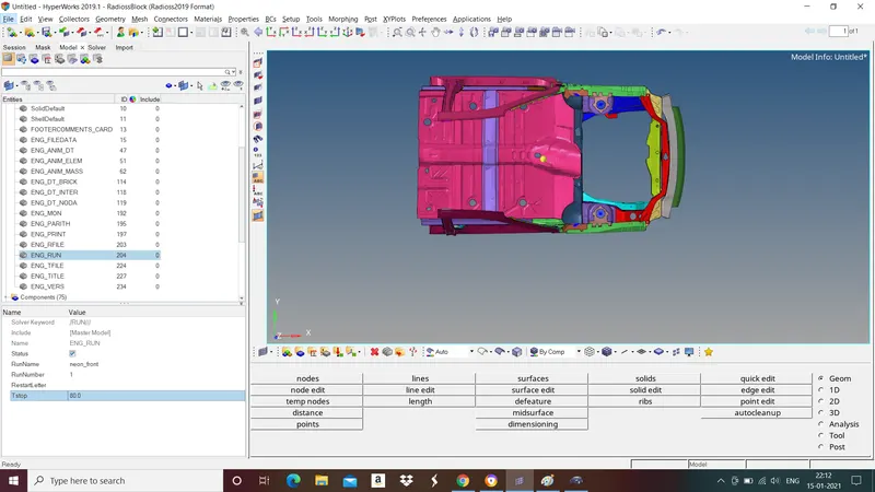
To give simulation time go to model browser in tab bar>cards>ENG_RUN>Give run time in Tstop.
Output Requests
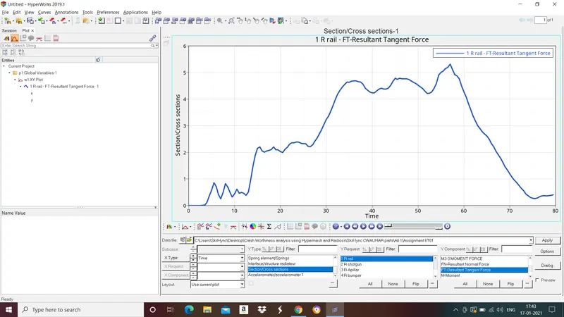
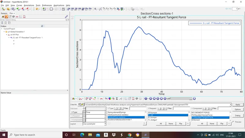
- Sectional force in the rails at location of indicated node 174247.
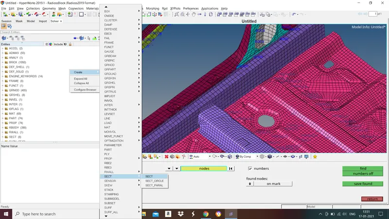
To create the cross section go to solver browser>right click select sect>sect.
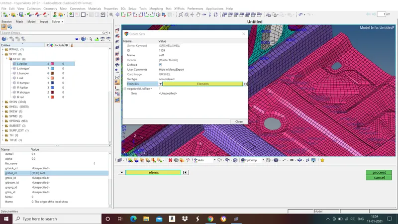
To select shells right click "grshel_id" section>create>click on elements>select shell elements and select proceed>close.
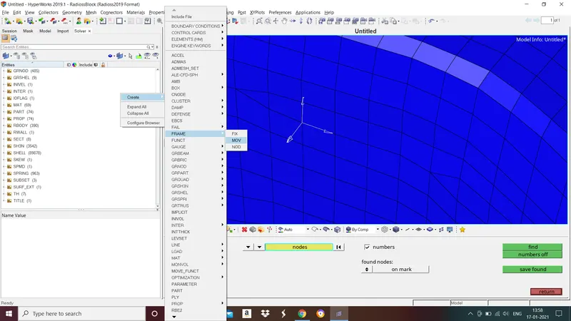
Now create moving frame for section. Go to solver browser>right click>Frame>mov.
- In first from left "node" select the node where frame must be located.
- In second "node" select x axis.
- In third node select xy axis.
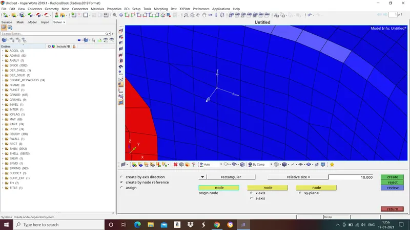
Now goto section again in Frame_id select the created frame.
Now we need to call outbput block, to do that go to slover browser>right click, in create>TH>SECTIO.
In entity IDs select the cross section.
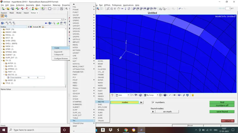
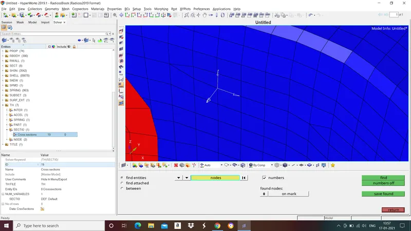
Follow the same procedure to create section for remaining cross sections.
- Acceleration curve received on the accelerometer at base of B pillar (on B pillar rocker)
To create accelerometer go to solver browser>right click IN create select ACCEL. Under "node_id" select a node on b pillar where we want to create accelerometer and give "Fcut" value as 1.65.
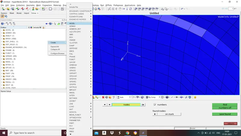
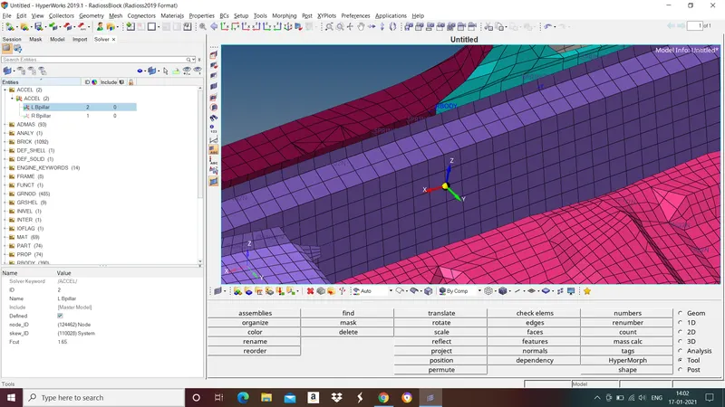
Now we need to call outbput block to do that go to slover browser>right click, in create>TH>ACCELEROMETER.
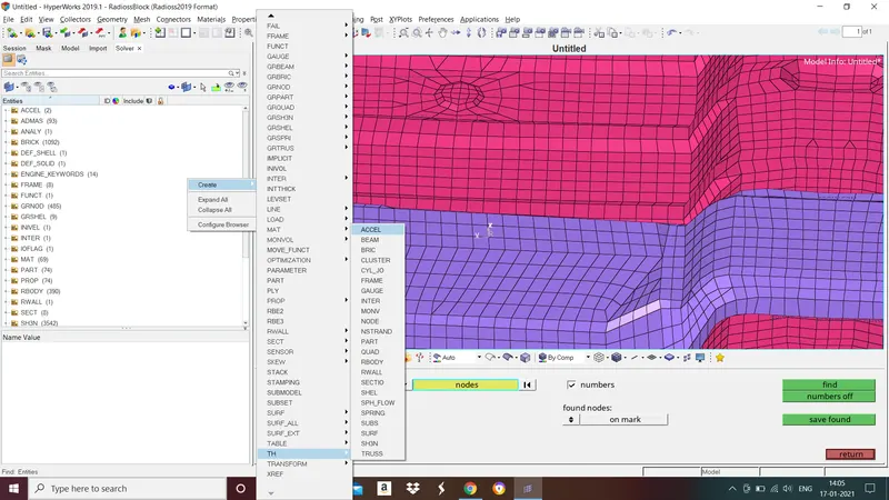
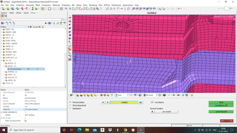
In enitity IDs select the accelerometer.
- Intrusions on the dash wall 66695,66244.
To check instrusions on dash wall at 66695 and 66244 node Ids.
Go to "find" in tools select nodes>right click and select by id>give node id and select ok.
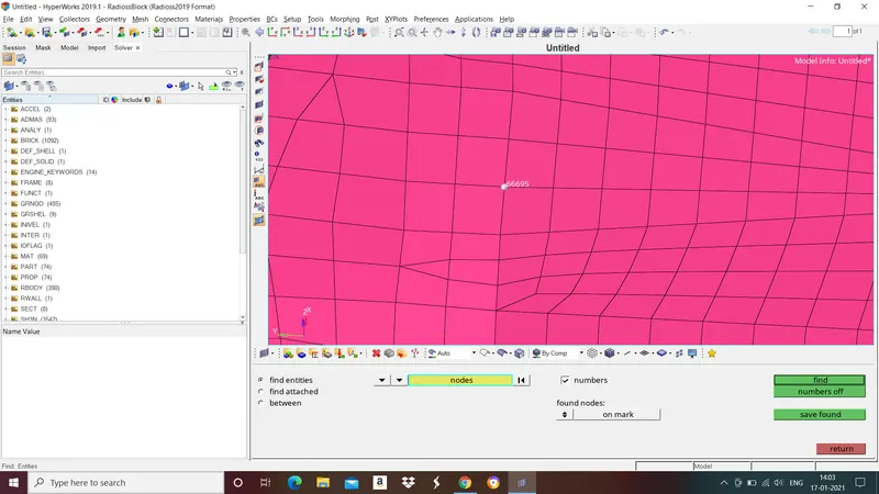
We need create moving Skew to do that go to solver browser>right click and select skew>mov.
- In first from left "node" select the node where frame must be located.
- In second "node" select x axis.
- In third node select xy axis.
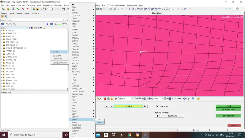
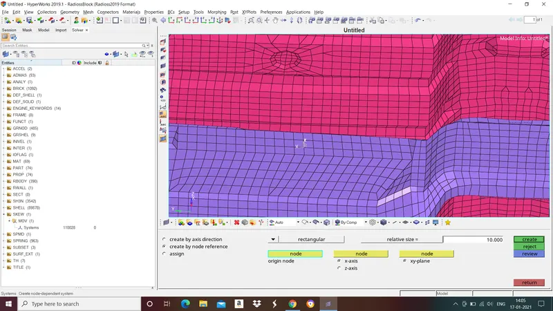
Now we need to call output block for above nodes to do that goto solver browser>right click and select create>TH>NODE.
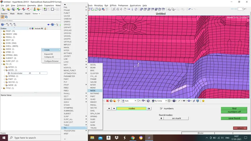
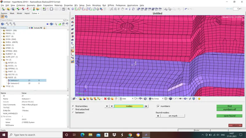
In entity IDs select node and select moving skew in Iskew. Do the same for another node.
Errors faced:
Final part of any pre processing is checks for errors and fixing it. To check the model open the file in Hypercrash to do that go to file>export>give file name>export.
Now go to Applications>Hypercrash>select the unit system>open.
In Hypercrash>file>import>select the rad file>open.
Go to Quality>Model checker>Run.
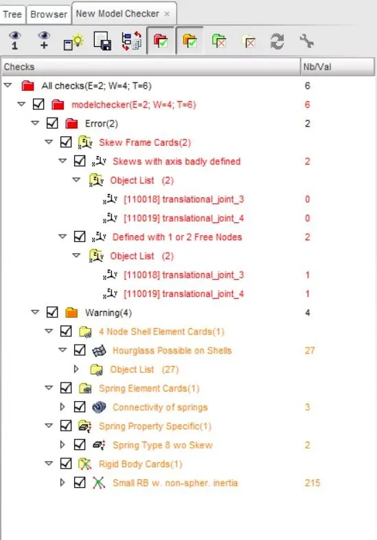
I deleted those translational joints skews since those are not required for the simulation.
After fixing errors export the file by go to file>export>select the folder and give file name>export.
To run simulation open the file in HyperWorks>Analysis>save the file>radioss.
SIMULATION RESULTS:
Animation result:
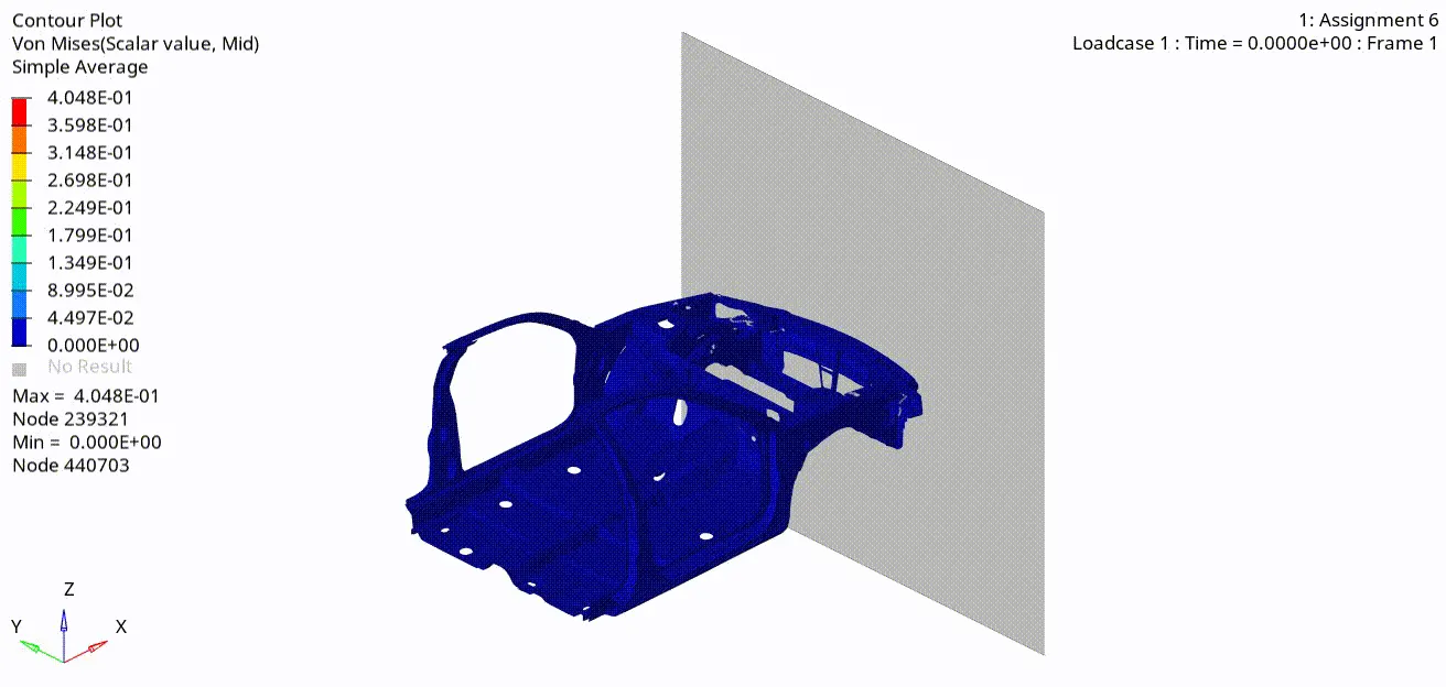
It can be observed from the animation that frontal portion of the body getting deformed very quickly as it hit the rigid wall but after a certain point we can observe that less deformation taking place in the body. This is due to the cross section which helps in better force distribution. Because of that there will be less impact in the dash wall which results in less injuries to occupants.
Internal energy and Kinetic energy:
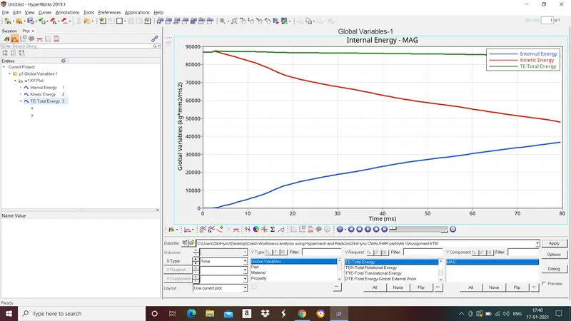
The kinetic energy that body has before the impact is transformed into internal energy, mostly by plastic deformation of the car body material (Body in white). Total energy is the sum of Kinetic energy and internal energy.
Contact energy and Hourglass energy:
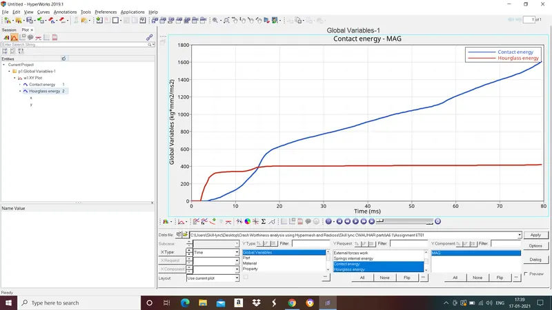
Since we have checked for penetrations and there were no penetrations found which helps in less contact energy developed in the body. There is very less hourglass energy is developed in the body because we have used fully integrated elements with recommended properties.
Intrusion at node 66695 and 66244 ids
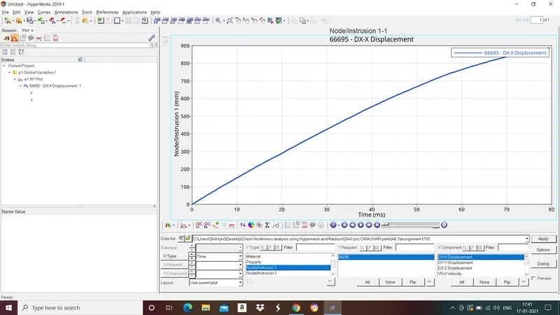
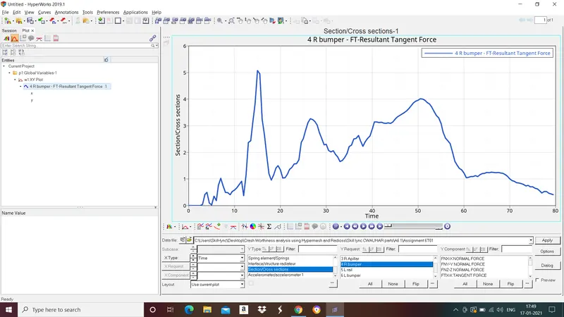
Cross sections
1. Right side rail
2.Left side rail
3.Right shotgun section
4.Left shotgun section
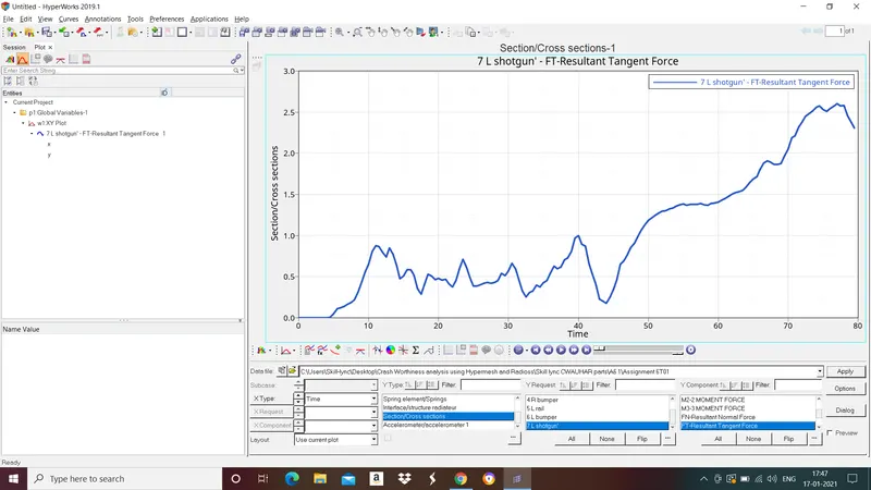
5.Left A-pillar section
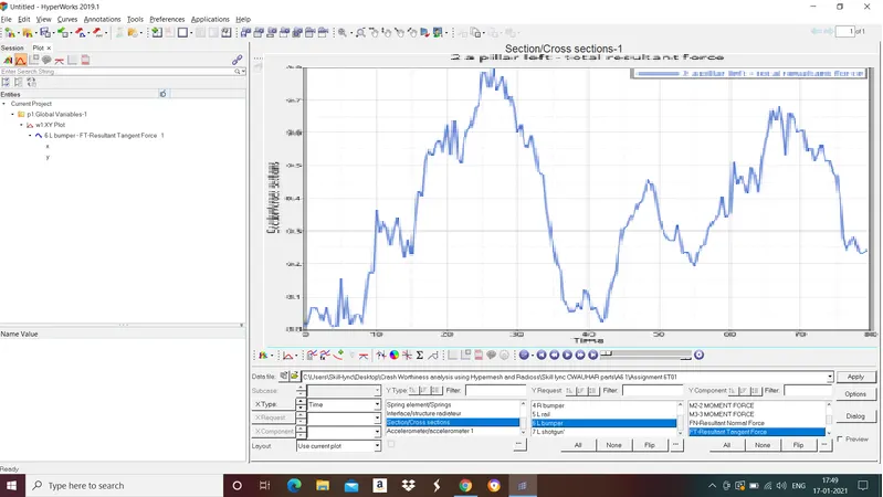
6.Right A-pillar section
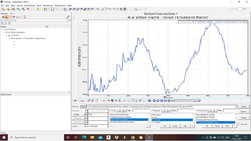
7.Left bumper
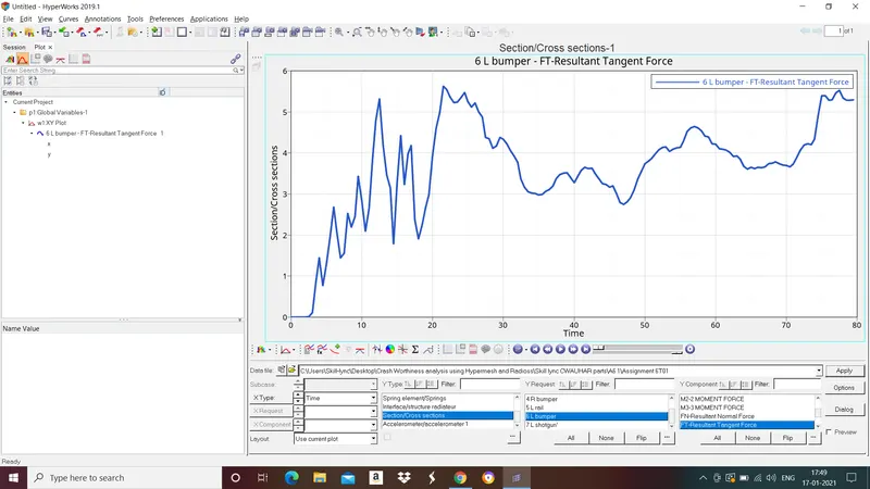
8.Right bumper
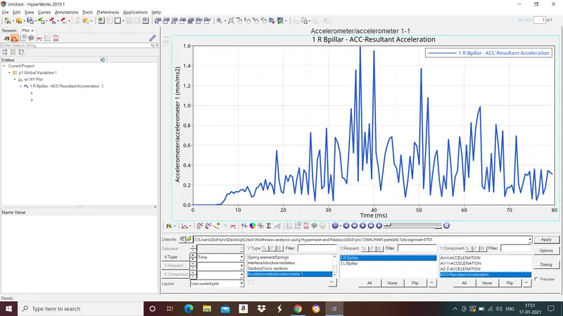
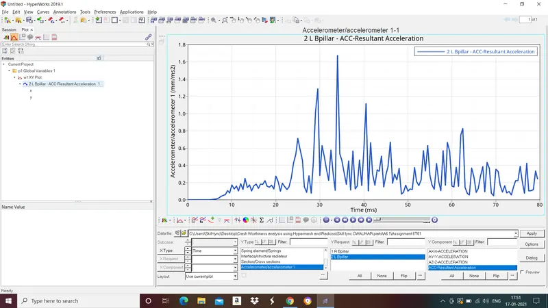
Acceleration on B-pillar
Ride side
Left side
Below values were noted at the end of simulation
Energy Error: 0 - -1.4%
Mass error: 0.01429% - 0.02991%
Simulation time: 5679.24 seconds
No. of cycles:80001
CONCLUSION:
The case for frontal crash BIW of car was setup seccessfully and simulation for the same was run.