To check for the geometrical errors, mesh with the given element Quality criteria and Connect different parts using suitable Connectors for Rear Suspension Assembly
AIM : To check for the geometrical errors, mesh with the given element Quality criteria and Connect different parts using suitable Connectors for Rear Suspension Assembly.
METHODOLOGY :
- Geometry Cleanup.
- Assign PID.
- Mid Surface Extraction for sheet metal components and meshing with given element quality criteria.
- Surface meshing and volume meshing for thick components with given element quality criteria.
- Connect different parts using suitable Connectors.
PROCEDURE :
STEP 1 : Input CAD file to ANSA.
Goto 'File'>'Open'>select the CAD file>'ok'.
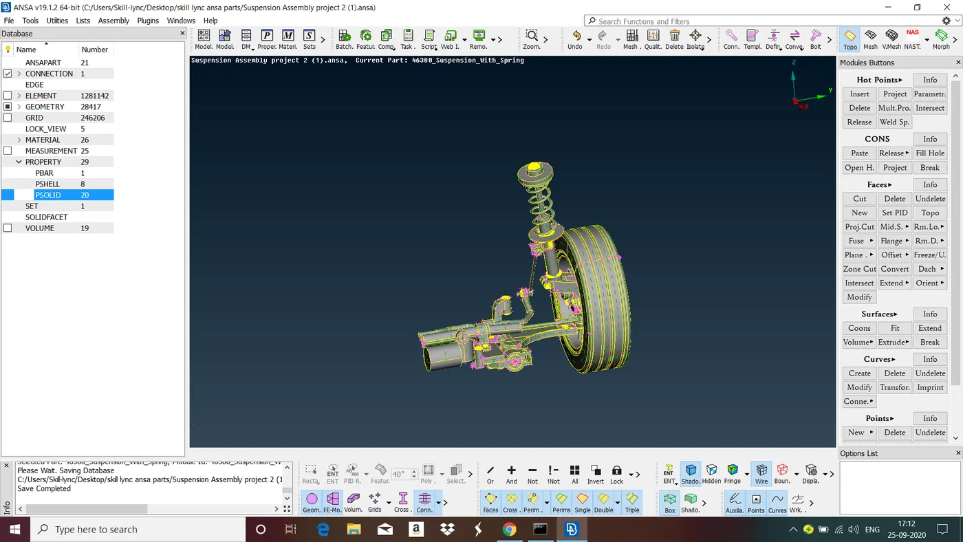
Fig : Rear Suspension Assembly
The CAD file is read and topology is applied. You should see the part as shown. Change the view of the part to better understand the geometry. Notice that as by default the visibility mode of the model is set to ENT (Entity), you can see the red, yellow and cyan CONS (Curves ON Surfaces). The coloring has to do with the connectivity of the Faces.
Red: a Single free edge CONS
Yellow: a Double CONS shared by two neighboring connected Faces
Cyan : a Triple CONS shared by three or more connected Faces.
STEP 2 : Geometry Cleanup
To make things clearer, you can activate and deactivate the visibility of each of the three types of CONS separately using the “Single”, “Double” and “Triple” flag buttons located in the FOCUS toolbar. De-activating here the “Double” flag only the free red and triple cyan CONS are left visible. Apart from the free edges of the sheet metal there are other openings (gaps, untrimmed Faces etc.) that must be corrected.
Start cleaning up the geometry of the model by Click on the “Checks” button, located in the “Tools” toolbar on the top of the screen and select “Geometry”.The Checks Manager window opens. Here you can select the type of problems that may exist in the geometry of the model to be investigated by activating the corresponding flag in the lower part of the window. Keep the default options and click Execute. ANSA can identify and isolate on the screen the problematic areas that require the user’s attention.
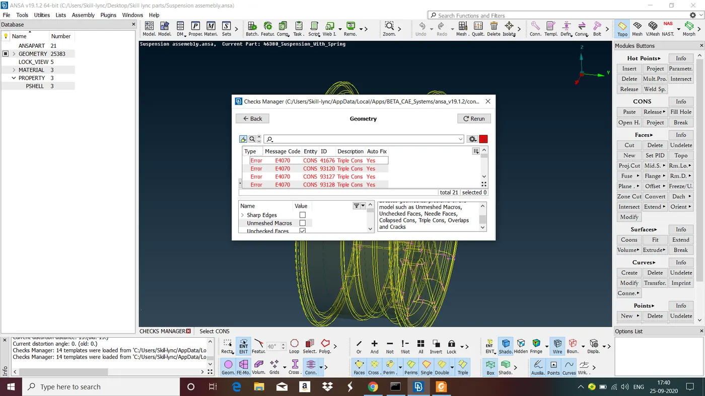
Fig : Geometrical errors present in the rim.
ANSA identifies a total of 21 errors in the geometry of the model. You can highlight any of the problematic areas by left-clicking on it, or isolate it on the screen by right-clicking on it and selecting “Show only”. Depending on the type of the problem ANSA also offers the option to automatically fix it.
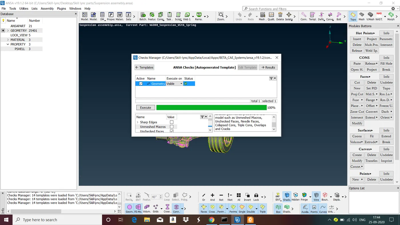
Fig : Checks manager showing zero geometrical errors.
Now the model is free from geometrical errors we can move to next step.
STEP 3 : Assign PID for each parts
Goto 'property Manager'>right click select 'New' change the name of the PID as you want select 'ok'>select the PID right click select apply>select the part that you want to create PID>close property manager.
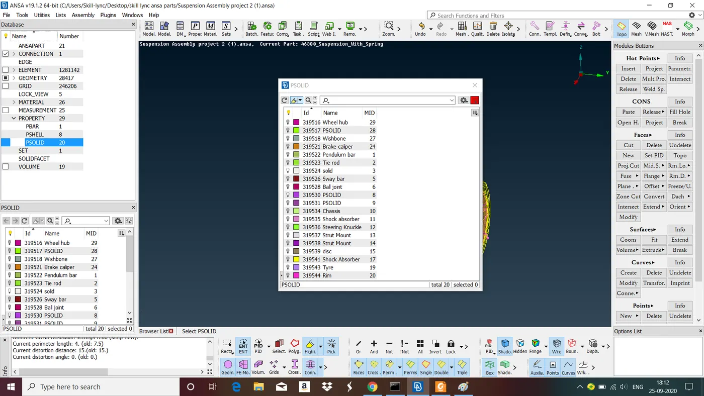
Fig : Assigning PID for each parts.
STEP 4 : Mid Surface Extraction for Sheet Metal Components.
We take Midsurface for the components having thickness less than 5mm. We can generate mid surface by two methods.
1. Auto Method : In this method we can generate mid surface of the given component in one shot using 'Skin' and 'Casting' options.
Advantages : Gives mid surface in one shot and less time consuming.
Disadvantages : May give improper result for complex geometry.
2. Manual Method : In this method we take midsurface of the given component entity by entity using 'Offset' and 'Middle' options.
Advantages : Gives accurate result.
Disadvantages : More time consuming.
Since the sheet metal components in the model have uniform length along its length we go with auto method.
To take midsurface for components having uniform length goto 'Middle surfaces' in 'Faces'>select 'Skin'>Select the component that you want to take midsurface and middle click>give offset value>select 'yes' or 'no' for 'Delete original faces' dialogue box.
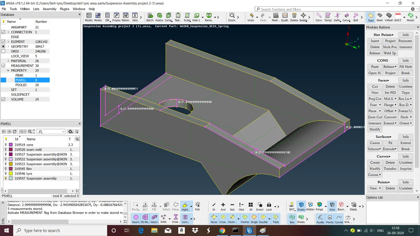
Fig : Above part has uniform length along its length.
We follow the same steps explained in above to generate midsurface for components having uniform thickness along its length.
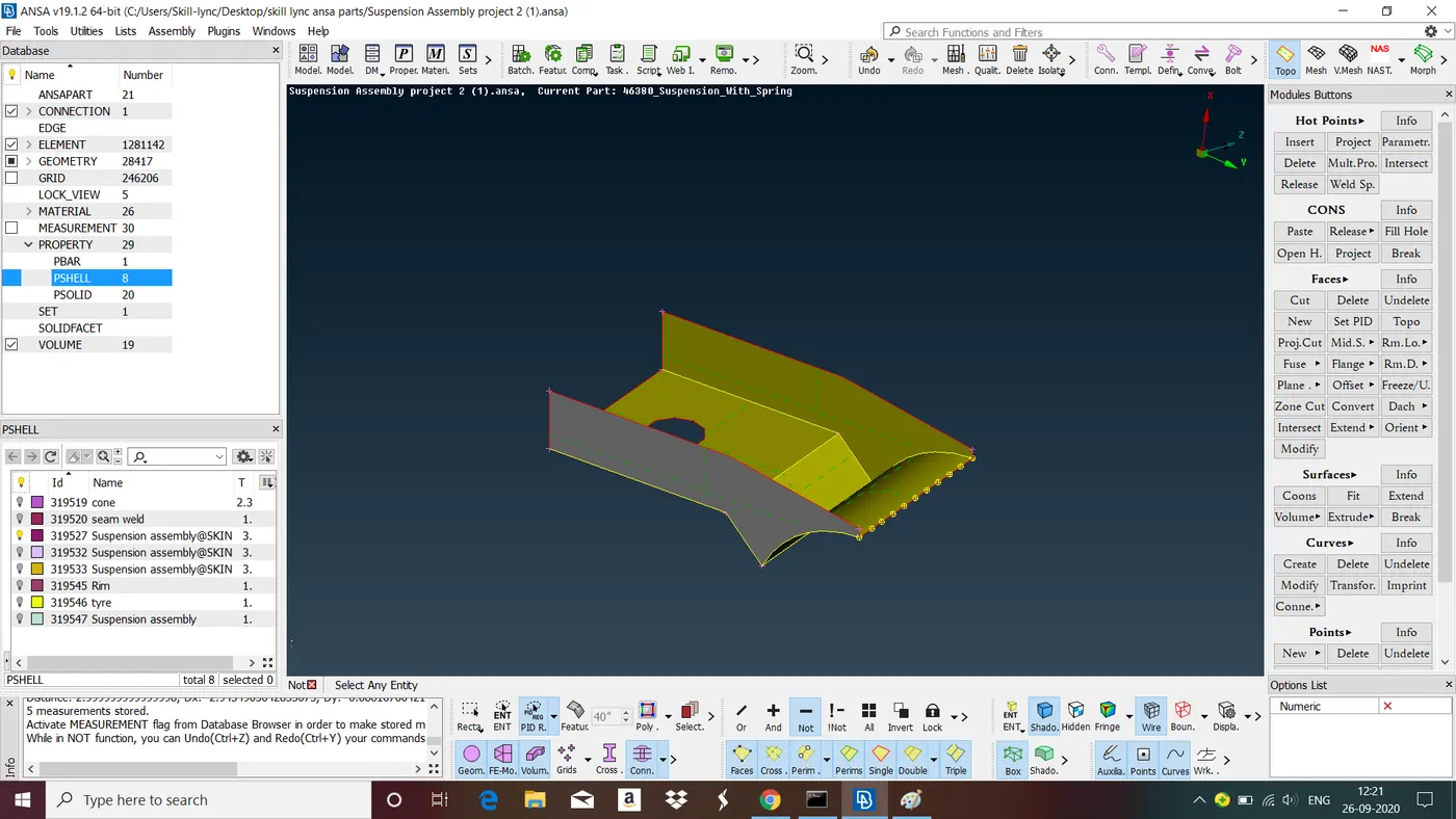
Fig : Midsurface of the component.
We follow the same steps to generate midsurface for other components.
STEP 5 : Meshing for middle surface generated components.
A mesh is a network that is formed of cells and points. It can have almost any shape in any size and is used to solve partial differential equations. Each cell of the mesh represents an individual solution of the equation which when combined for the whole network results in a solution for the entire mesh.
steps involved in meshing
1. Define element size
To give element size goto>'Length' in 'perimeters'>select the component give length size>select 'ok'.
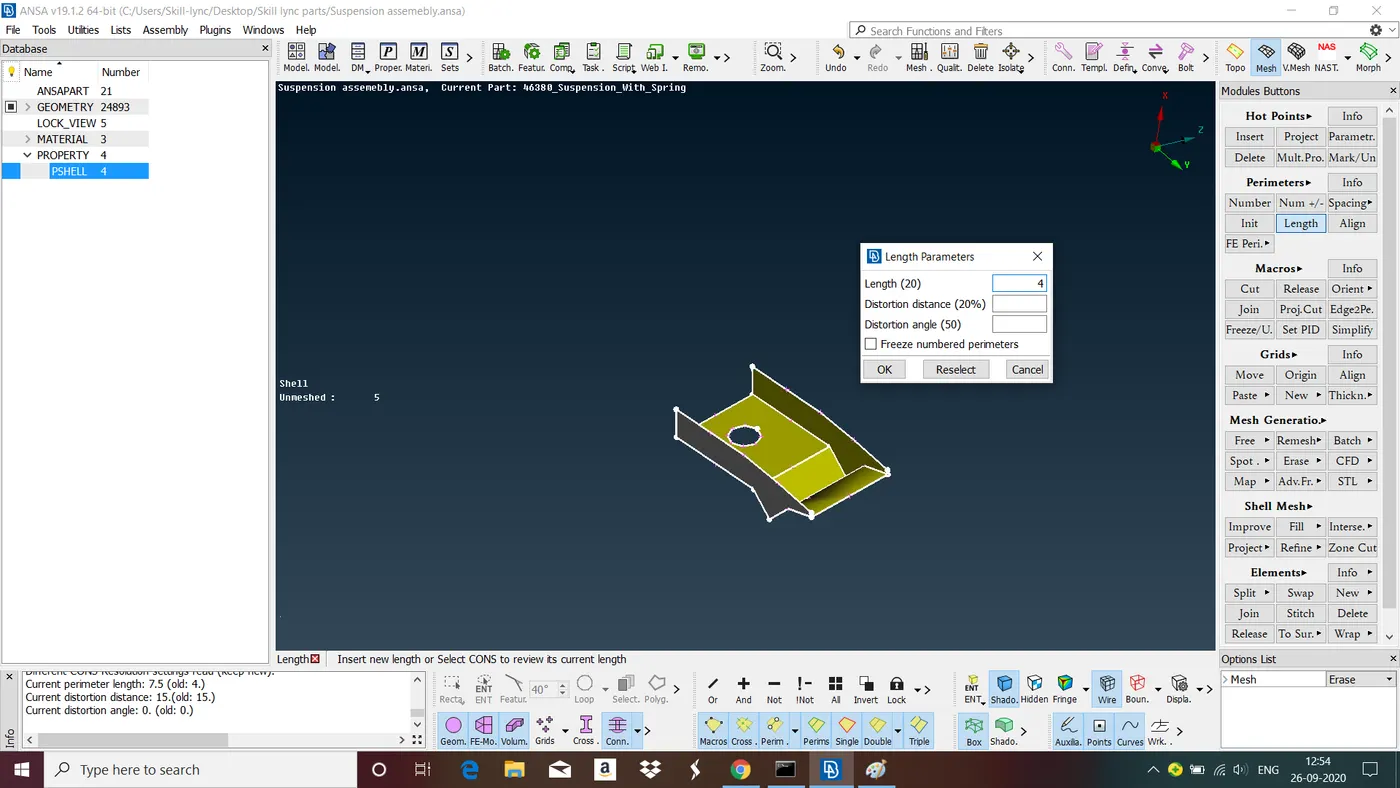
Fig : Giving element size for the mid surface generated component.
2. Choose element type
To give element type goto 'Mesh parameters'>in 'Basic' select element type (usually we use mixed for meshing of sheet metal components)>give Target length, 'Minimum target length' and 'Maximum target length'>select 'ok'.
Given Mesh Parameters
|
S.No |
Mesh Parameters |
Value |
|
1 |
Target/Average length |
4 |
|
2 |
Minimum Length |
2 |
|
3 |
Maximum Length |
6 |
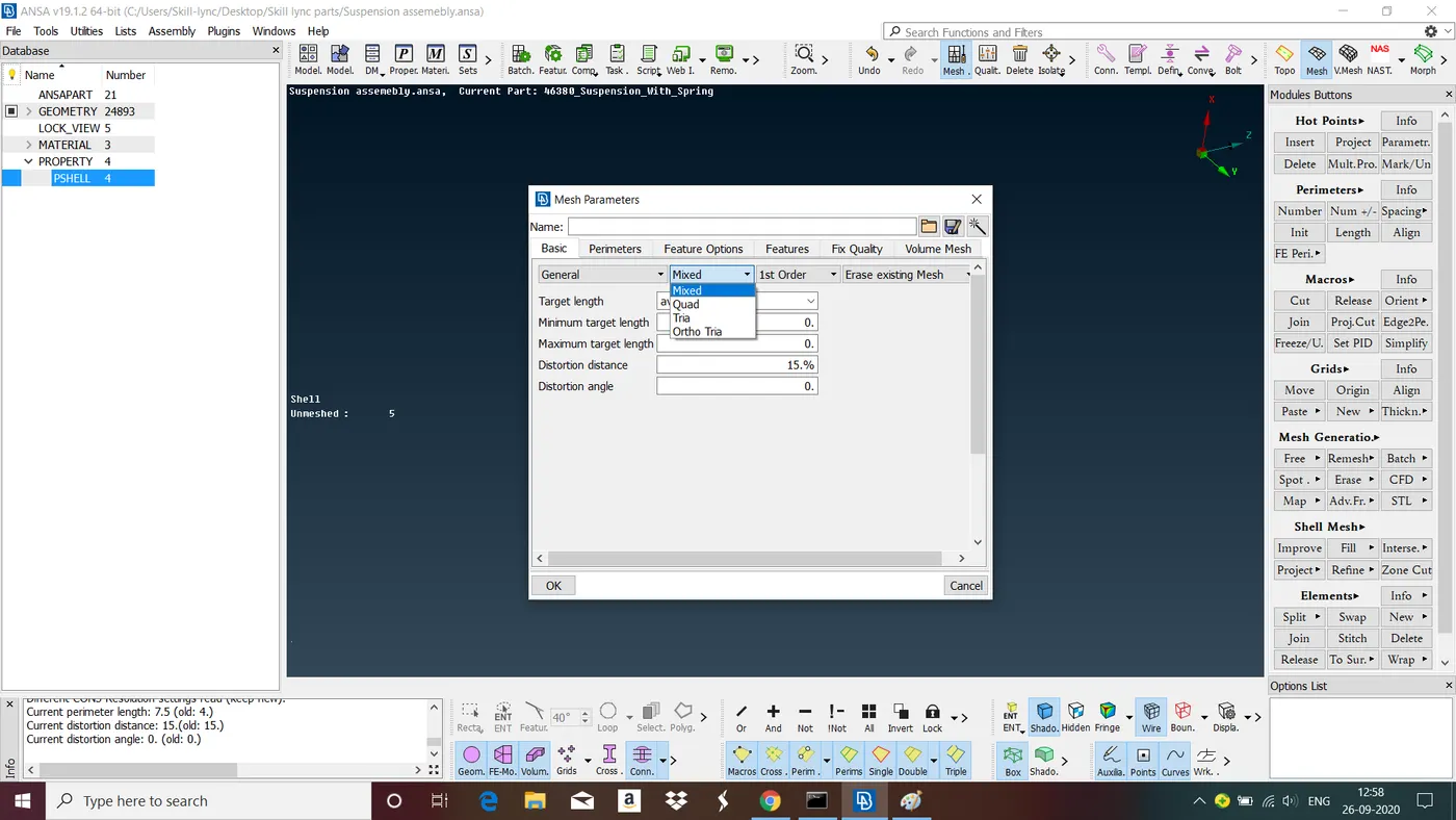
Fig : Selecting Element type.
3. Give quality criteria
-
The shape of Elements in FE Analysis must be distorted from their Ideal shapes when meshing the irregular or complex geometric shapes.
-
Every element is designed to work properly within a certain range of shape distortion. Exactly how much distortion and what type of distortion is allowed before an element degenerates depends on factors such as element type, numerical procedures used in the element design, and so forth.
-
The Ideal shape of [2D Elements] a triangular element is an equilateral triangle and a quadrilateral, it is a square.
-
The Ideal shape of [3D Elements] a Tetrahedron element is a Regular or Isosceles Tetrahedron and a Hexahedron, it is a Cube etc.,.
-
If the actual shape that the element assumes after mapping onto model geometry differs too much from the natural shape, the element becomes degenerated and produces erroneous results.
- The major types of degeneration are Aspect Ratio, Skewness, Jacobian Ratio, Warping Factor, Maximum Corner Angle, Orthogonal Quality.
-
Generally, large angles between edges (close to 180 degree) are more degenerating than small angles (close to 0 degree).
-
Each FE mesh should be run through an element quality check, and degenerated elements should be eliminated.
-
In order to get reasonably accurate results, it is always important to generate a structured mesh with good quality parameters.
-
If Elements are Degenerated they will become too stiff and underestimate the deformations (Field Variables) and its derivatives like strain & stress values become erroneous.
Given Mesh Quality Critiria
| S.No | Quality Criteria | Value |
| 1 | Aspect | 3 |
| 2 | Warpage | 15 |
| 3 | Skewness | 45 |
| 4 | Jacobian | 0.7 |
| 5 | Minimum Quad Angle | 45 |
| 6 | Maximum Quad Angle | 135 |
| 7 | Minimum Tria Angle | 30 |
| 8 | Maximum Tria Angle | 120 |
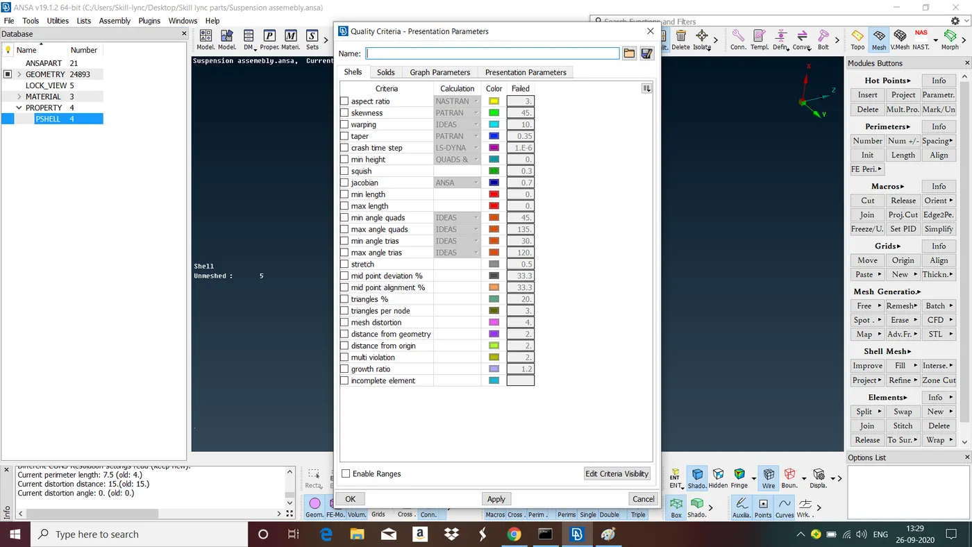
Fig : Giving Mesh Quality Critiria
4. Meshing
Now start meshing entity by entity using various types meshing tools provided by ANSA to get good mesh flow.
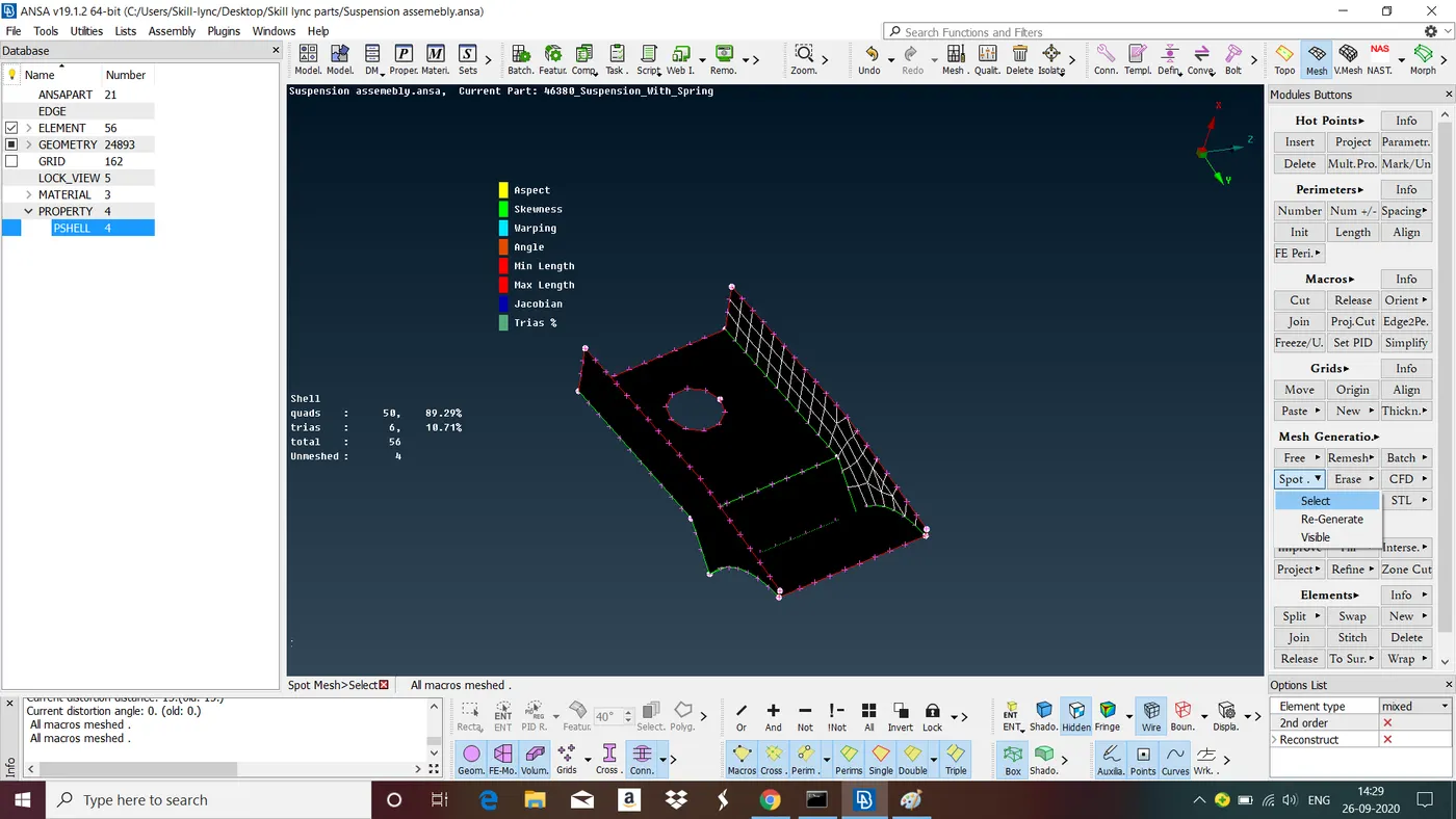
Fig : Meshing entity by entity using 'Spot' option.
5. Remesh for mesh quality improvement
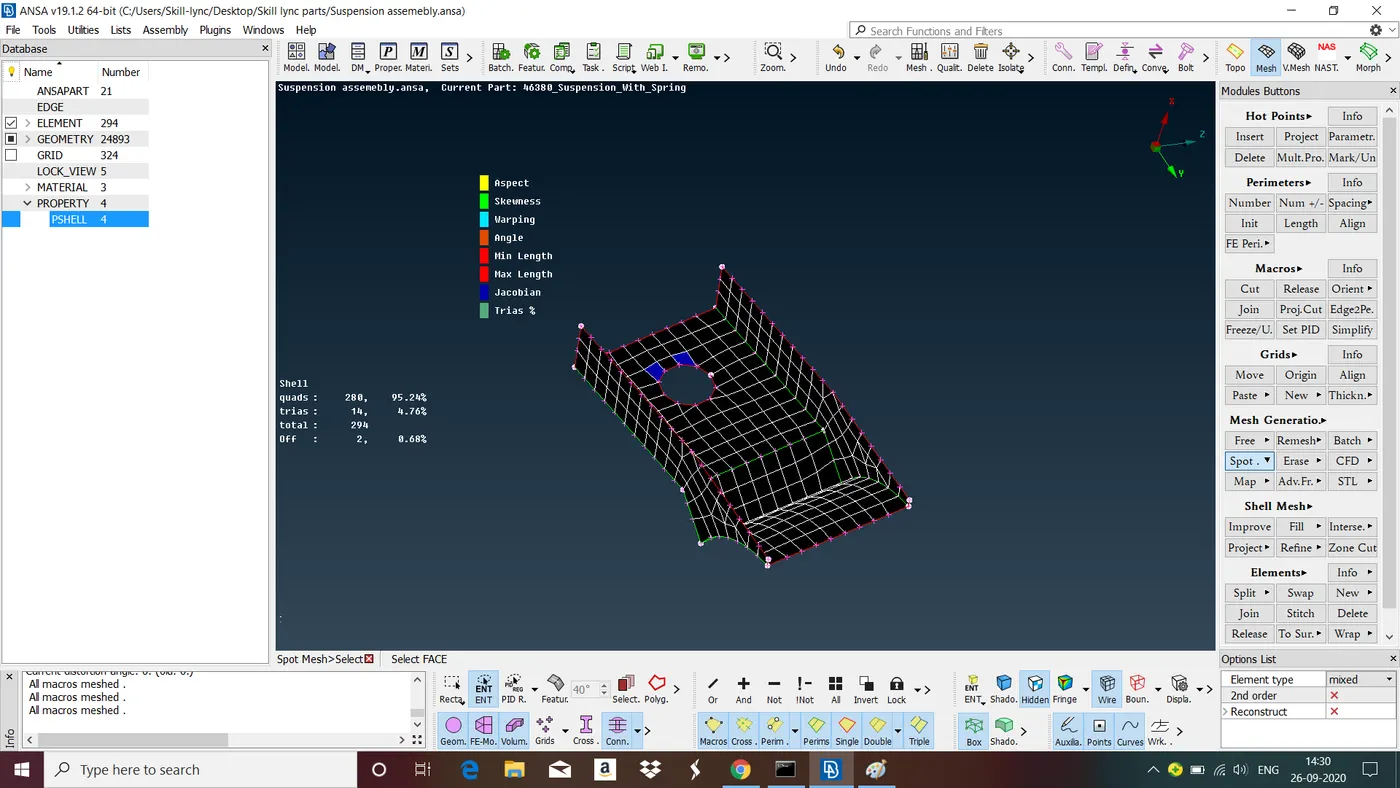
Fig : Component after meshing.
In the above figure we can see there are some mesh elements failing for quality criteria and number trias also more. The component after meshing it must be free from quality criteria errors and we should reduce number of trias as much as posiible. Improve the quality of the mesh by using various tools provided by the ANSA for ex : Reconstruct, Split, Swap, Join etc.
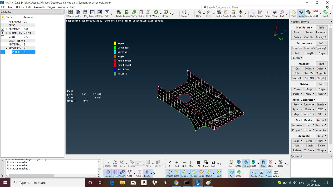
in the above figure we can see that after reconstructing the mesh, part is free from quality criteria errors and number trias also reduced.
Follow the same steps for meshing as explained in above for all midsurface generated components.
STEP 6 : Surface meshing and Volume meshing for Thick components.
- For tetra mesh we use only tria and ortho tria for mesh mesh generation.
- For flat sufaces use normal tria for mesh generation.
- For curved surfaces use ortho tria mesh generation because it captures the featues more accurately than normal tria.
- Generate good quality of tria surface mesh because these mesh only mapped into the volume while doing volume mesh.
Give Element size, Mesh Parameters and Quality Criteria as explained in above.
Quality Criteria for Tria Elements (Tyre and Rim)
|
S.No |
Quality Criteria |
Value |
|
1 |
Target/Average length |
6.5 |
|
2 |
Minimum Length |
5 |
|
3 |
Maximum Length |
10 |
|
4 |
Skewness |
45 |
Quality criteria for Tria (For other components)
|
S.No |
Quality Criteria |
Value |
|
1 |
Target/Average length |
4 |
|
2 |
Minimum Length |
2 |
|
3 |
Maximum Length |
6 |
|
4 |
Skewness |
45 |
Common Quality Criteria for Tetra elements are
|
S.No |
Quality Criteria |
Value |
|
1 |
Tet-collapse |
0.2 |
Surface Meshing :
Mesh the surfaces using various types of meshing tools provided by the ANSA to get good mesh flow. Defeature the curves which are fails for minimum length quality criteria but dont delete the features which are critical even if it is fails for minimum length. Use Reconstruct, Split, Swap, Join,etc to get better mesh flow.
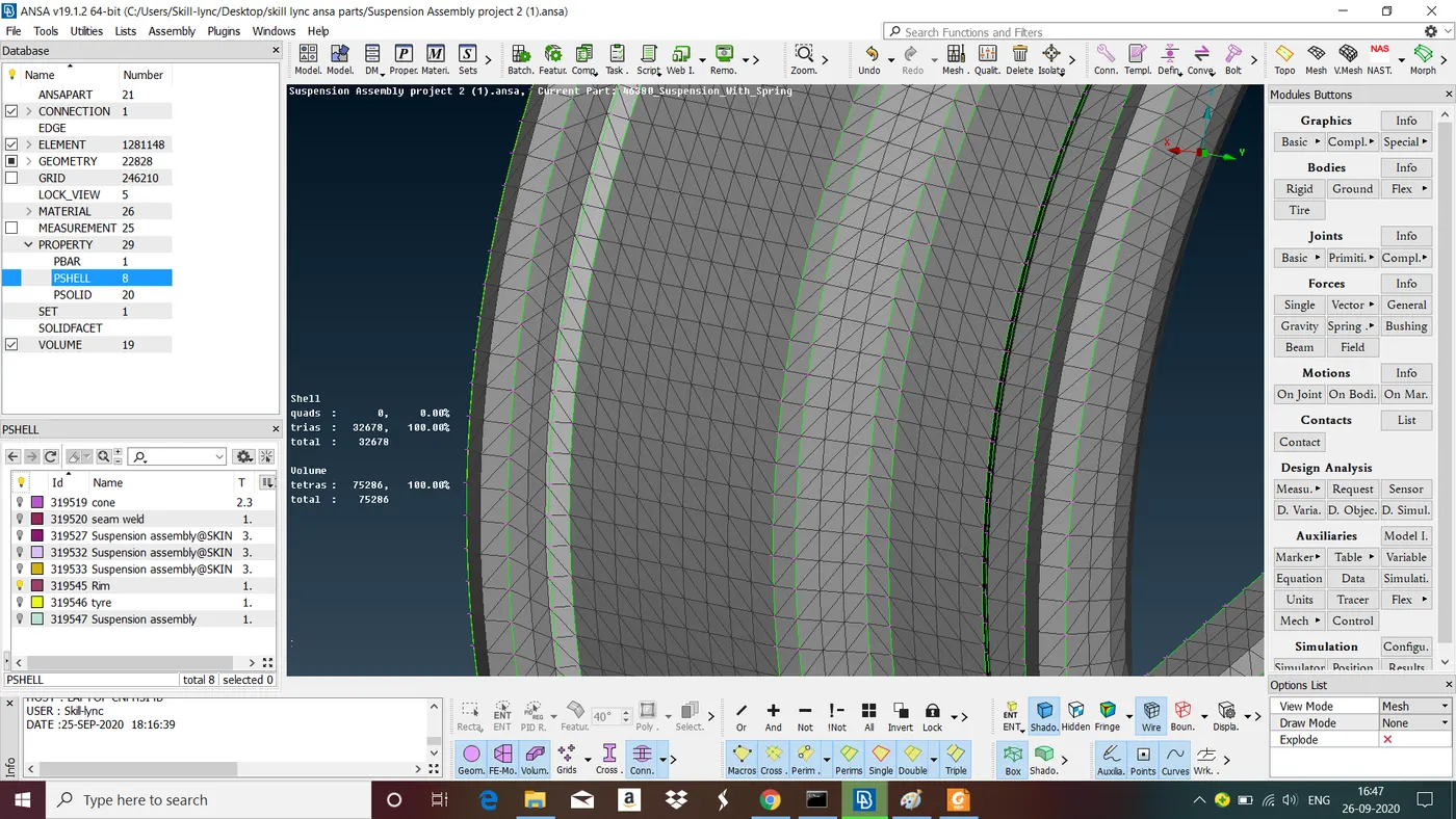
Fig : Curved surfaces are meshed with Ortho tria elements.
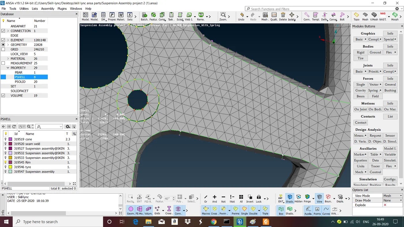
Fig : Flat surfaces are meshed with normal tria elements.
By following above steps mesh all surfaces for thick components.
Volume Meshing :
In order to mesh the component with tetra elements we must first define the Volume entity.
Activate the VOLUMEs>DEFINE function. Keep the Auto flag active in the Mode window. Left click on one of the Macros that form the volume. The Auto mode recognizes and selects all the Macros that form a closed volume. Press middle mouse button to accept. The Properties window appears so that we can assign a Property for the solid elements that will be generated. As there is no available Property in the list click on NEW to create one. A new Solid Property card appears. Click OK to accept the default values. Next, the Part Manager appears, in order to allocate the Volume entity to a Part.
Select NEW [PART] to create a new Part. A new empty Part appears in the Part Manager. Click on the name and change it to "volume". Then left click on the new part to place the Volume entity in it. Make sure that the VOLUME. Visibility flag button is active, otherwise you cannot see or select a Volume entity.
To verify the Volume entity creation, activate the VOLUMEs>INFO function and pick the Volume. This becomes highlighted for a preview. Press ESC to exit.
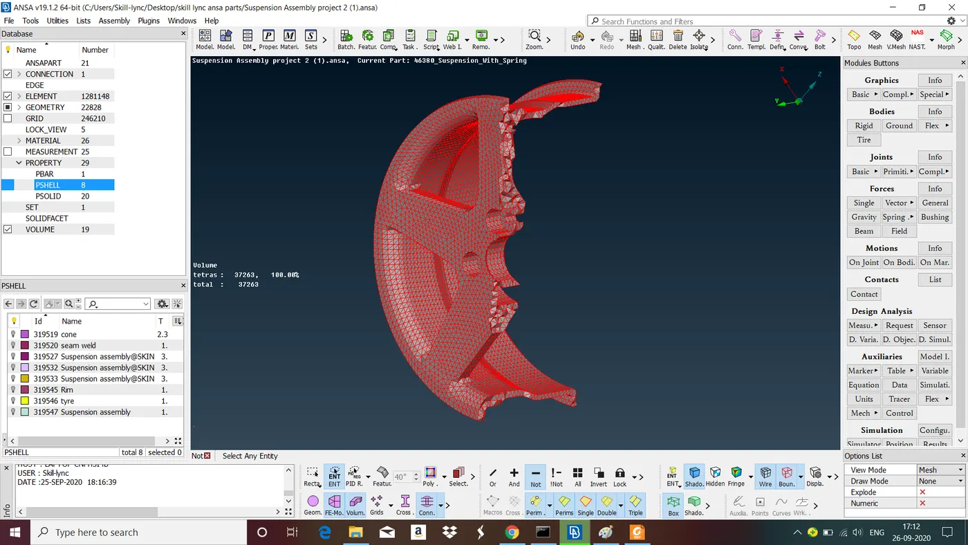
Fig : Rim After volume Meshing.
Follow the same steps to do volume meshing for all thick components.
Modelling of Spring :
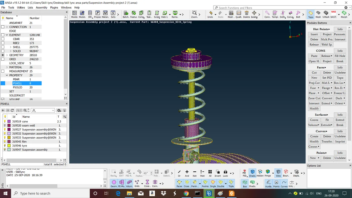
Fig: Spring in the suspension Model.
Springs, Torsional beams,etc can be volume meshed but it takes more time to simulate. We can use 1D model instead of 3D model by using CBAR Elements.
Step 1 : Convert spring into a curve by using 'Middle' option in 'Curves' and make it a one single curve by 'connect' 'multi' option in 'Curves'.
Step 2 : In solver deck module>'Elements'>'CBAR'>in curves select box selection>select curve by box selection>ok>give Element length>Give the name as 'spring'>ok.
Step 3 : In property manager in PBAR double click 'spring' property ID. In 'A'(area) right click>select 'select from list'>give radius of circle and thickness(if the bar is hollow)>'ok'>close the PID manager.
Step 4 : Now goto Quality criteria>Presentation Parameters>tick 'Line elements presentation' to get 3D view.
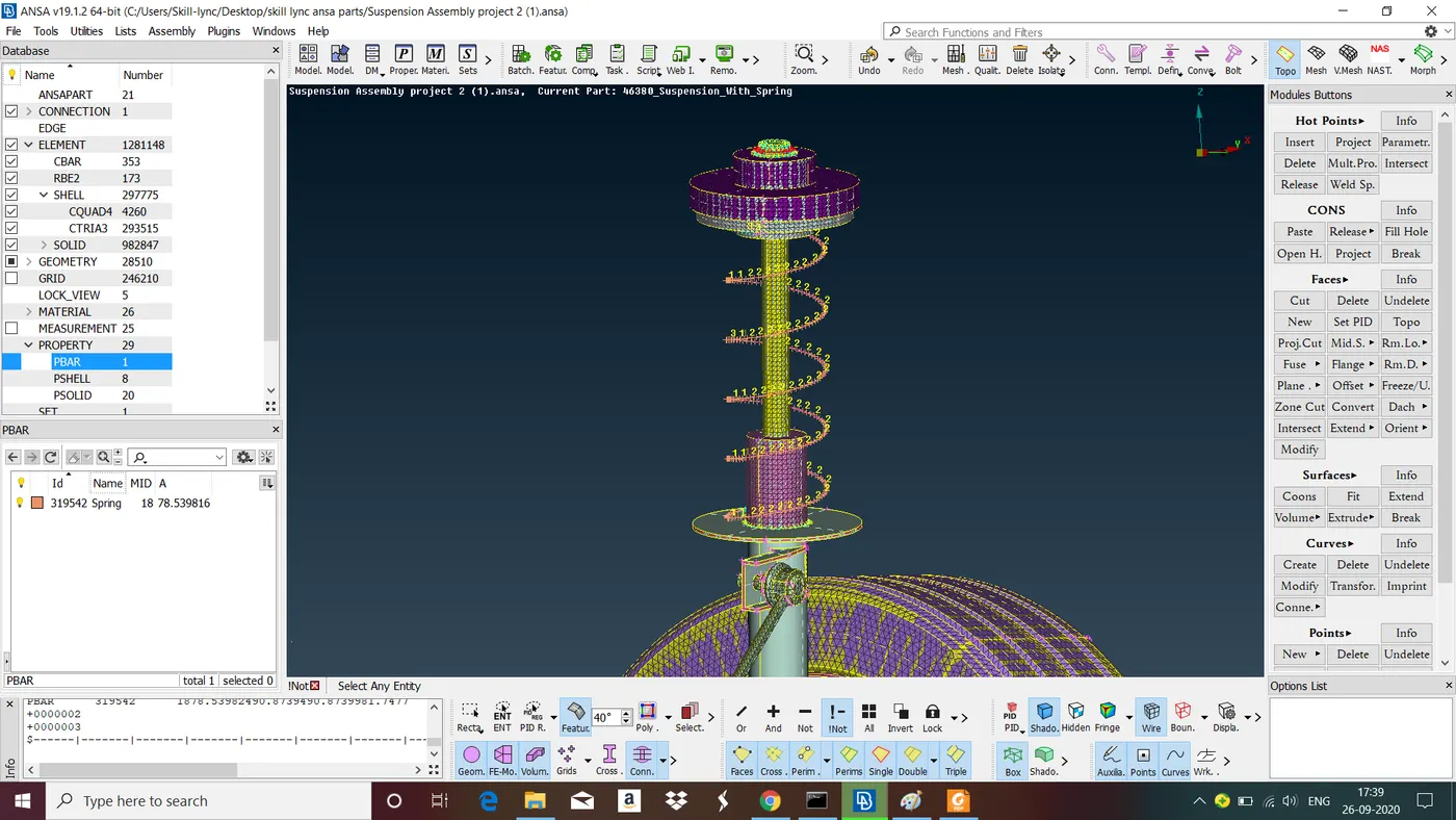
Fig : After 1D modeling of spring.
STEP 7 : Connections
If the two components connected by temporary or permanent joint we have give connections in FEA for analysis.
We use RBE2 elements to establish firm connection(ex: Fasteners) between the parts.
To give firm connection
goto Solver deck>'Elements'>'RBE2'>'Many nodes'>select the slave nodes and middle click. Master node provided by itself>'ok'.
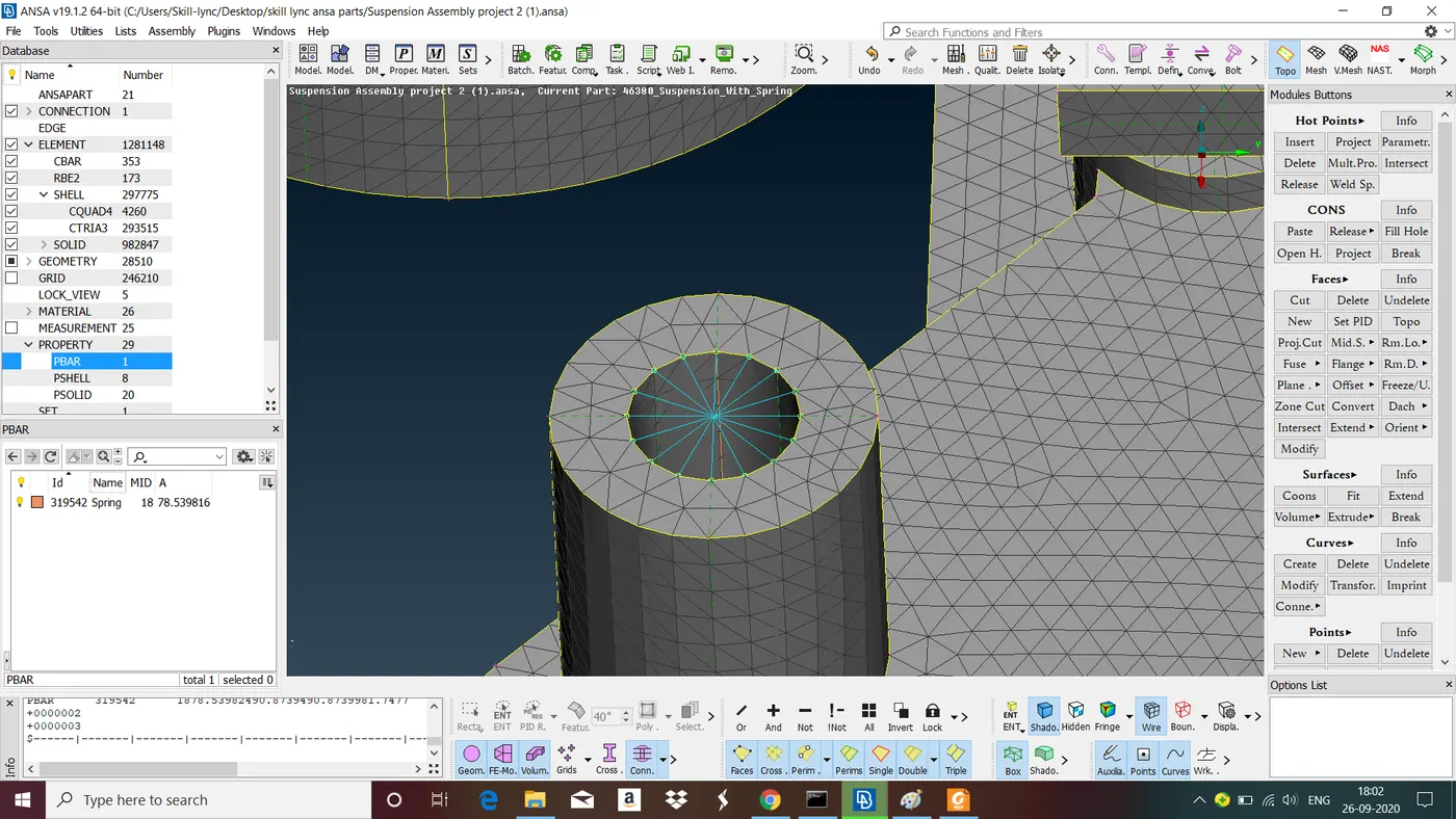
Fig : Bolt hole connection by using RBE 2 many nodes elements.
Follow the same steps to give bolt hole connection wherever required.
Welding connections :
step 1 : Create a curve of the length of the weld.
step2 : Convert curve into seam line by goto convert (in assembly manager)>select the curve>select seam line>ok.
step 3 : Now goto Connections(in assemebly manager)>select the seam line and middle click> in p1 right click>in modify press f1>select the feature. do the same in p2.
step 4 : In clipboard give FE Rep type, search distance, Base sheet and all the necessary parameters>Apply>Realize>close Connections Manager.
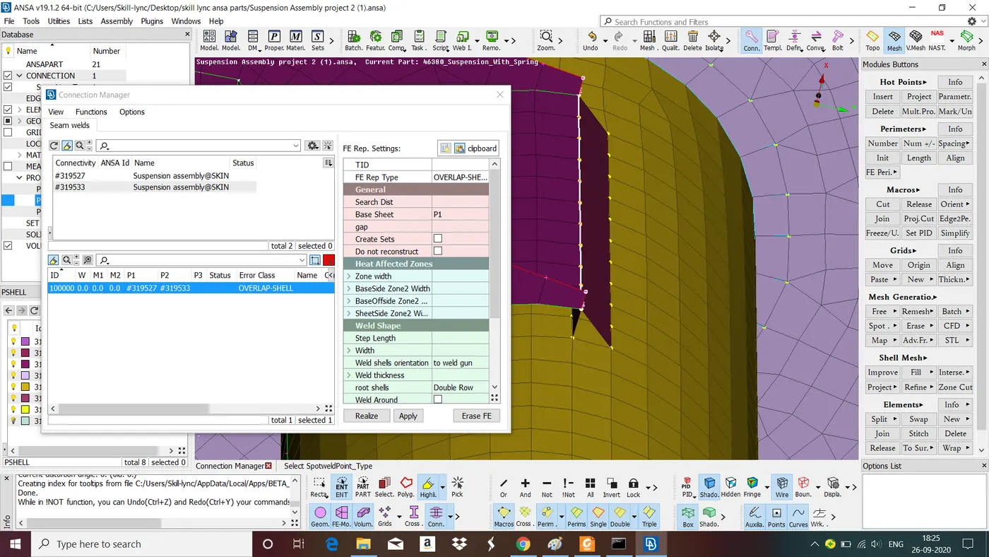
Fig : Welding Connections Between the parts.
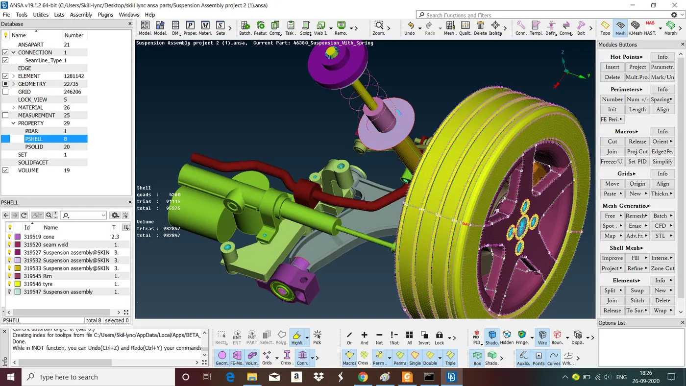
Fig : Model after giving Connections.
One half of the suspension assembly is completed now we have to mirror this half to get other half so the model will be completed as one rear assembly.
To do this goto>'Transform'>'Copy'>'Symmetry'>select 'Mirror 3 points plane'>select three colinear points and middle click>'Finish'.
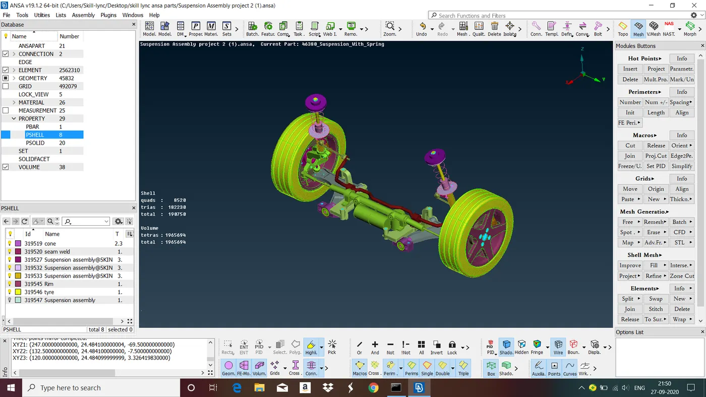
Fig : Final Model
LEARNING OUTCOME : In this challenge we have learned all the steps involved in geometry cleanup, midsurface extraction, 2d meshing, 3d meshing and connections.
CONCLUSION :
- Suspension model checked for geometrical errors and meshed with given quality criteria and obtained good mesh flow.
- The parts of suspension assembly connected by using suitable connectors.