Assignment 5
AIM:
- To create the mesh for bumper assembly.
- To discuss in detail about the given 6 cases.
PROCEDURE:
1.To create the mesh for bumper assembly.
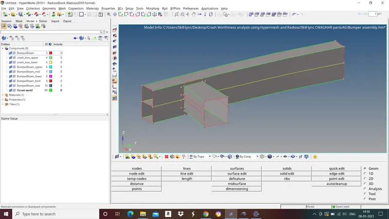
Import the model by go to file>import>geometry>select the file>import.
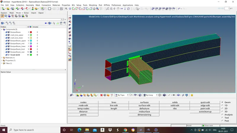
Go to 2D>automesh>select element size and element type>mesh.
2.To discuss in detail about the given 6 cases.
a.Run the crash tube model as it is
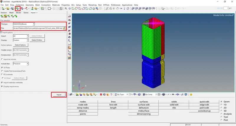
To import the model goto file>import>solver deck>select the file(0000.rad)>import.
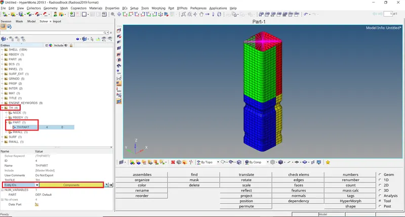
To create time history plots(TH/PART) for parts go to solver in tab menu>right click select create>TH>PART.
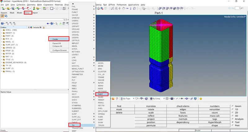
In TH>PART>TH PART>in entity IDs select the parts.
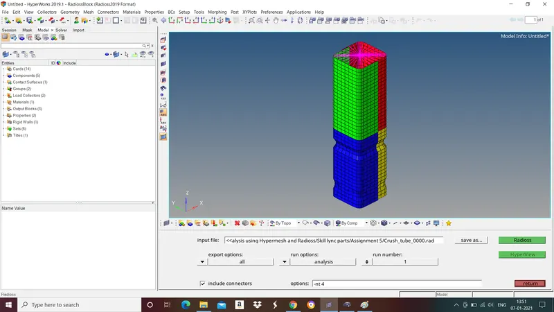
To run the simulation go to Analaysis>Radioss>save the file>radioss.
Simualtion results:
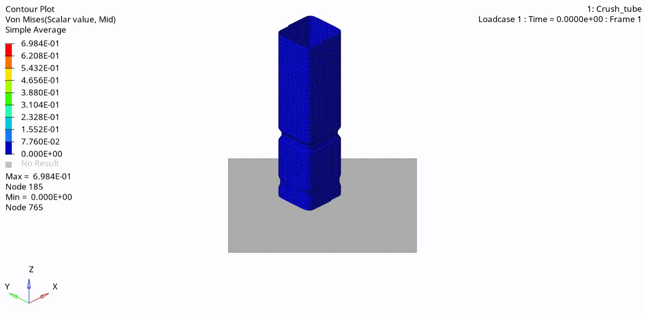
Fig: Vonmises Stress
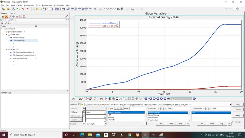
Fig: Internal enegry and contact energy graph.
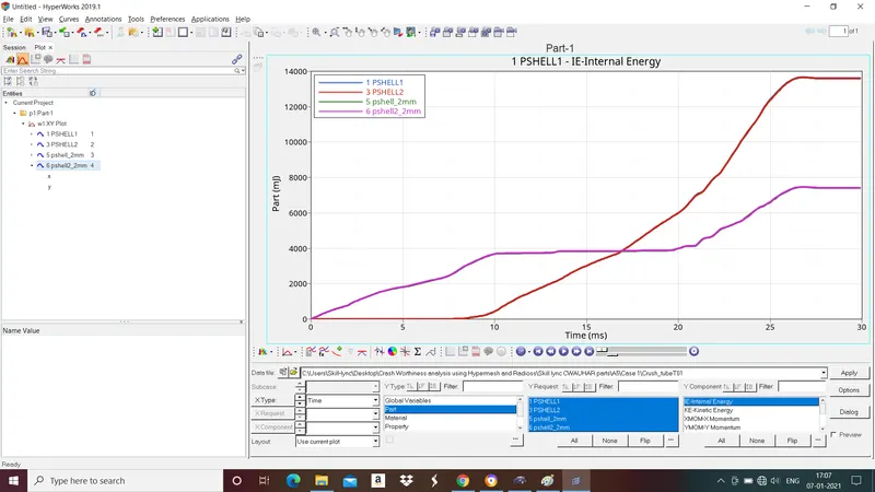
Fig:Internal energy graph (Parts).
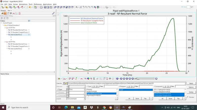
Fig: Rigidwall forces graph.
b. Change the Inacti=6 and run.
"Inacti" means Action to take if initial penetration exist.
Inacti=6(Gap is reduced and scaled. Gives good accuracy).
Import the rad file to hypermesh as explained in above. To change Inacti=6 go to groups in tab menu>groups>self contact>change inacti 0 to 6.

To run the simulation go to Analaysis>Radioss>save the file>radioss.
Simulation results:
Fig:Vonmises stress
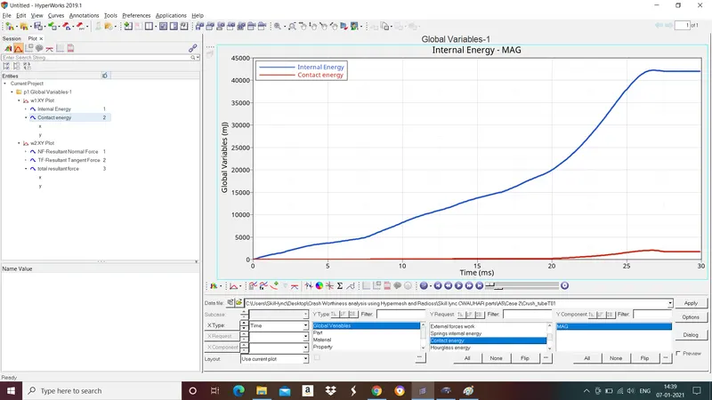
Fig:Internal energy and contact energy graph.
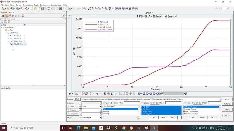
Fig:Internal energy graph (Parts).
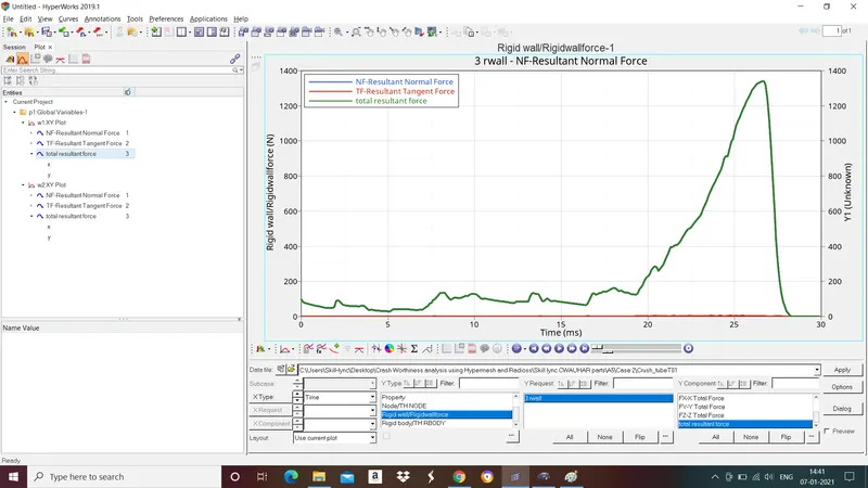
Fig: Rigidwall forces graph.
c. Create the type 11 contact and run.
Type 11 contact is an edge to edge contact.
To provide type 11 contact for the parts go to groups in tab menu>self contact>in card image select type 11 contact>select master and slave segments and give all the necessary parameters.
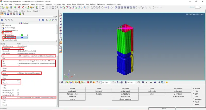
To run the simulation go to Analaysis>Radioss>save the file>radioss.
Simulation results:
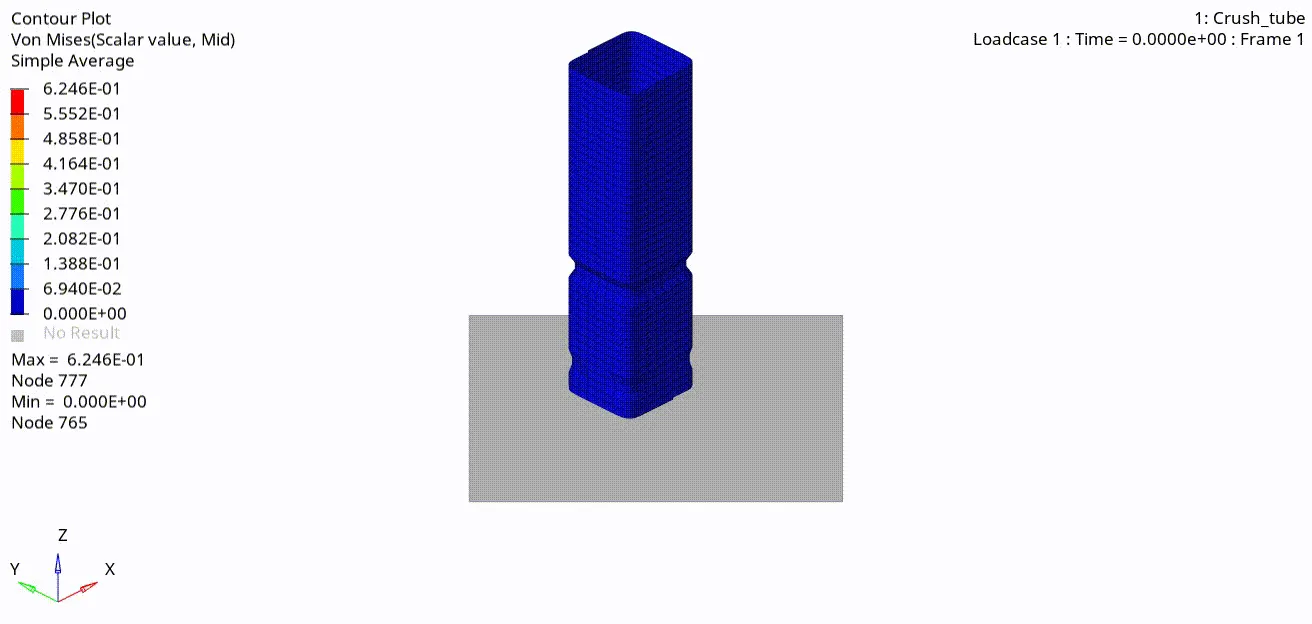
Fig:Vonmises stress
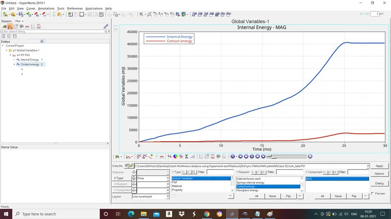
Fig:Internal energy and contact energy graph.
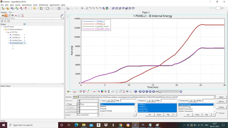
Fig:Internal energy graph (Parts)
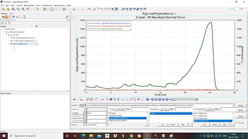
Fig: Rigidwall forces graph.
d.Remove both notches and remove boundary condition on rigid body node then run.
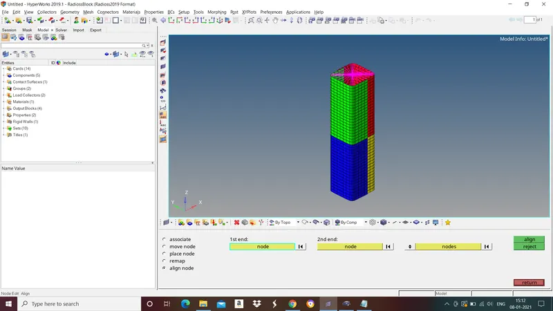
Import the rad file to hypermesh as explained in above. To remove notches go to geom>node edit>align node>select the nodes and select align.
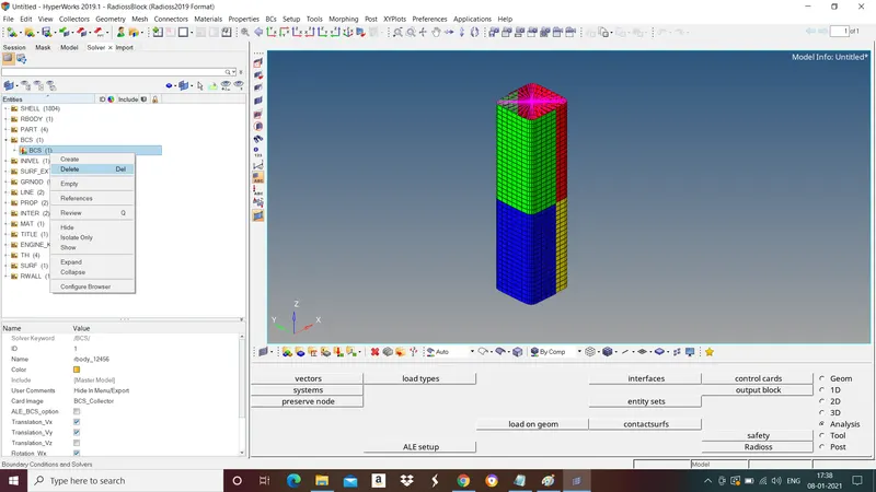
To remove boundary conditions go to solver tab menu>BCS>delete BCS.
To run the simulation go to Analaysis>Radioss>save the file>radioss.
Simualtion results:
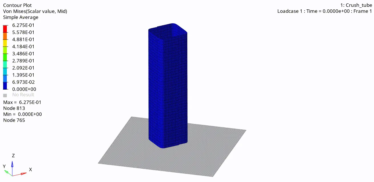
Fig:Vonmises stress
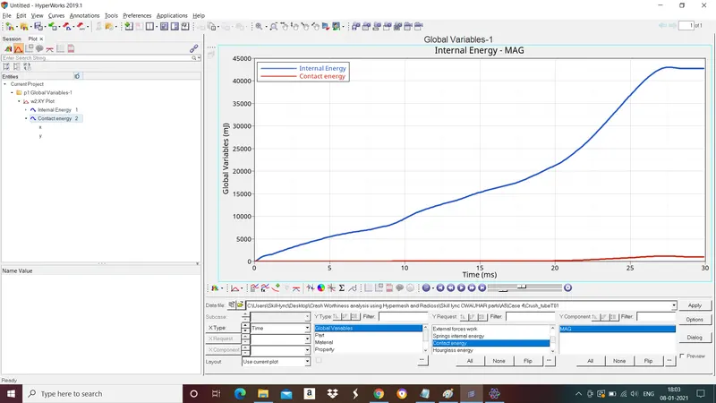
Fig:Internal energy and contact energy graph.
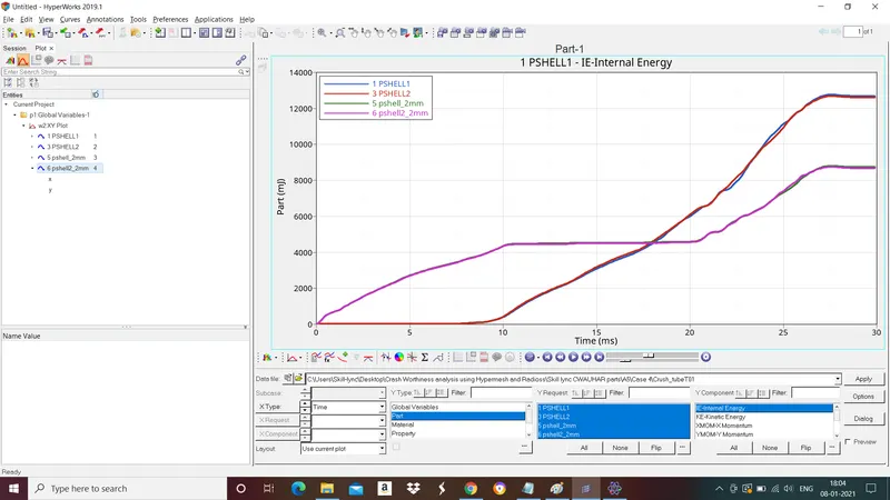
Fig:Internal energy graph (Parts)
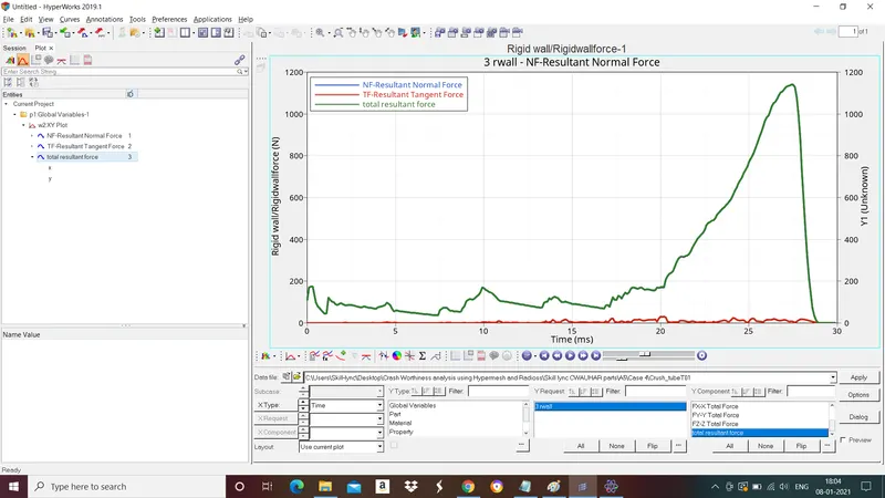
Fig: Rigidwall forces graph.
e.Create a new notch in the middle ,select the whole section and run.
Import the rad file to hypermesh as explained in above. To create a notch go to tools>Translate>select the nodes, direction vectors and give magnitude>translate.
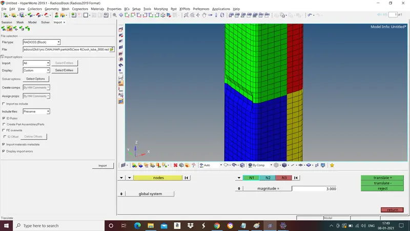
To run the simulation go to Analaysis>Radioss>save the file>radioss.
Simualtion results:
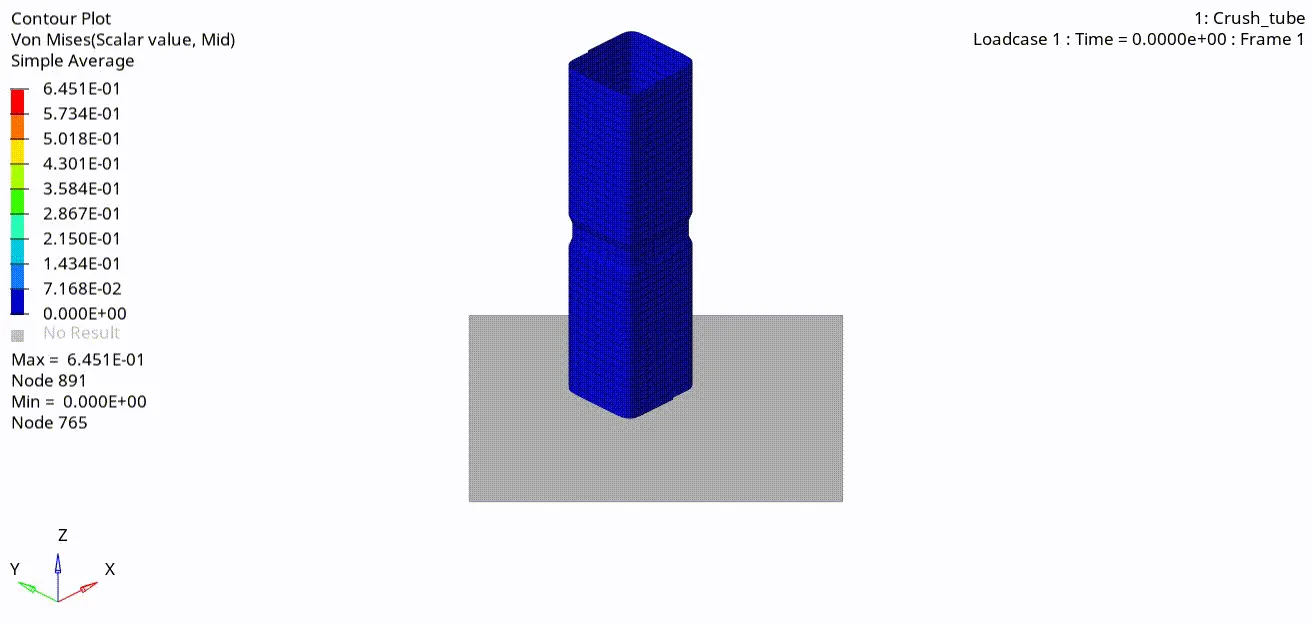
Fig:Vonmises stress
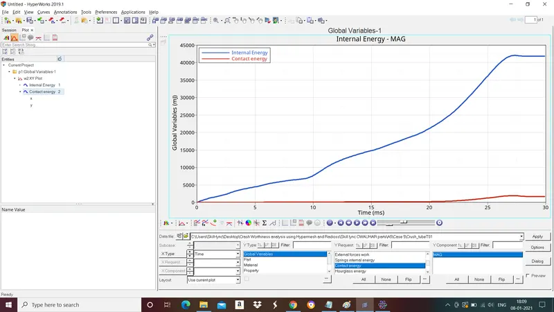
Fig:Internal energy and contact energy graph.
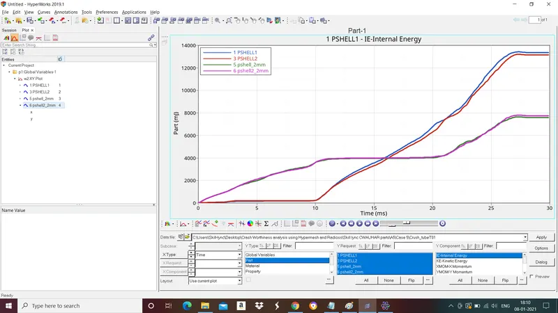
Fig:Internal energy graph (Parts)
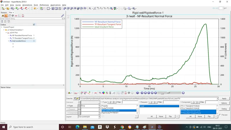
Fig: Rigidwall forces graph.
f.Create a new notch with nodes only from opposing 2 faces and run.
Import the rad file to hypermesh as explained in above. To remove notches go to geom>node edit>align node>select the nodes and select align. To create a notch go to tools>Translate>select the nodes, direction vectors and give magnitude>translate.
To run the simulation go to Analaysis>Radioss>save the file>radioss.
Simulation results:
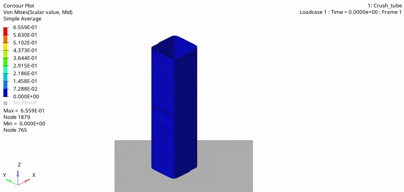
Fig:Vonmises stress.
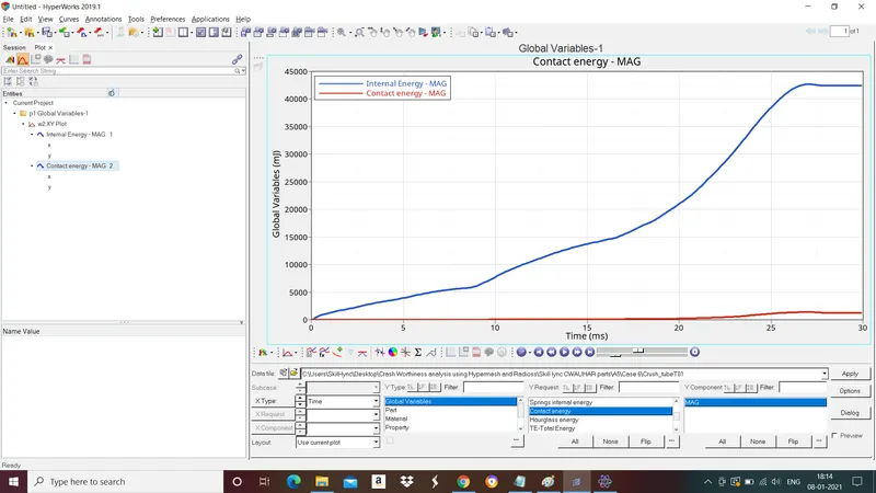
Fig:Internal energy and contact energy graph.
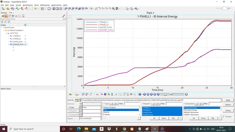
Fig:Internal energy graph (Parts)
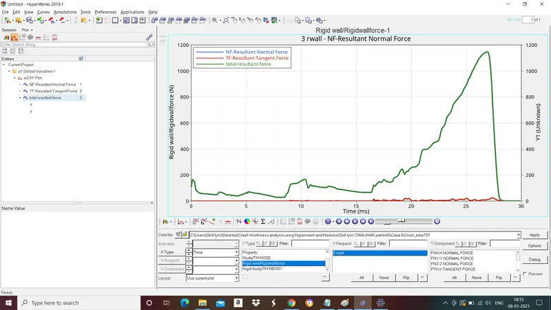
Fig: Rigidwall forces graph.
- Why there is a change in the internal energies?
The change in internal energy is due to the notch. With the removal of notch internal energy decreases.
- How does the notch affect the results?
Notches result in uneven stress distribution, leading to stress peaks known as the notch effect. The notch effect reduces the loading capacity and leads to early failure of material.
LEARNING OUTCOME:
Different types of Contact interfaces and its parameters.