To generate mid surface and meshing an automotive hood using HyperMesh
AIM : To generate mid surface and meshing an automotive hood along with quality criteria and thickness assignment.
METHODOLOGY :
- Import CAD Model
- Topology repair
- Midsurface extraction
- Assign thickness
- Meshing
- Remesh - Quality improvement
PROCEDURE :
1. Import CAD model to Hypermesh
Import geometry data via:
• Files > Import > Geometry>select the file>import.
• Common types of geometry files supported: Unigraphics (NX2, NX3, NX4, NX5).
• UG Part Browser : Import of *.prt files Requires an installation of Unigraphics to be available.
• CATIA (V4 & V5) : import of *.model files CATIA V5 license required to import V5 files.
• Pro/ENGINEER (Wildfire 2.0 & 3.0) : import of *.prt and *.asm files.
• IGES: Import of *.igs / *.iges files.
• STEP: import of *.stp files.
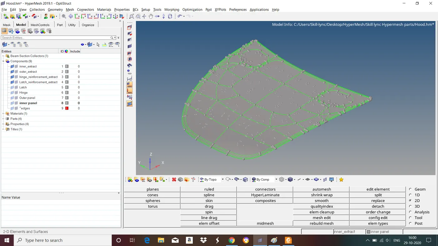
Fig : Given Hood Model
•Surface connectivity is controlled by the associated surface edges.
• If a surface edge is associated with more than 1 surface, those surfaces are considered to be connected (“equivalenced”).
• Surface edges are categorized, named, and colored according to the number of associated surfaces:
Free edge (red) :
• Associated with only 1 surface.
• Surfaces with a free edge between them are NOT equivalenced at that edge.
Shared edge (green):
• Associated with 2 surfaces.
• Surfaces are equivalenced.
Suppressed edge (blue):
• Surfaces are treated as though combined into 1 surface .
2. Topology Repair
Topology Repair consists of correcting connectivity errors between adjacent surfaces Possible errors include:
• Unconnected adjacent surfaces.
• Duplicate surface.
• Missing surfaces.
• Surface Deformations.
• Toggling the edges which are fails for minimum element length.
The Goal of Topology Repair is to restore the surface data to a perfectly clean representation of the part.
• Understand model size & scale to determine an appropriate global element size Set a cleanup tolerance based on the determined global element size.
• Set appropriate value in options, geom cleanup, and automesh : cleanup
• Cleanup tolerance specifies the largest gap size to be closed by topology functions.
• Tolerances > 15-20% of global element size can cause mesh distortions.
• Can change value multiple times for work on various areas of the model.
• Use topology display tools to decide what needs to be cleaned.
• Use equivalence to combine as many free edge pairs as possible.
• Make sure surfaces are not collapsed in undesirable manner.
• Use toggle to combine any remaining free edge pairs, 1 by 1.
• use replace function if more control is needed.
• Use find duplicates to check for any duplicate surfaces and delete them.
• Use filler surface to recreate any missing surfaces.
As we can see its an assembly contains 4 seperate components we have to do geometry cleanup seperately for each component.
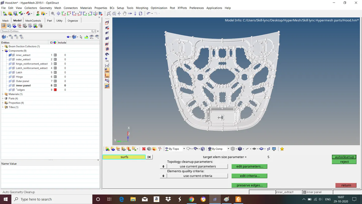
Fig : Performing topology cleanup for inner panel.
3. Midsurface extraction
Components which are having thickness less than or equal to 5mm we take midsurface for those components and mesh it with shell elements.
The child component extracted should be an exact replica of parent component.
To do this goto Geom>midsurface>select the surfaces>extract.
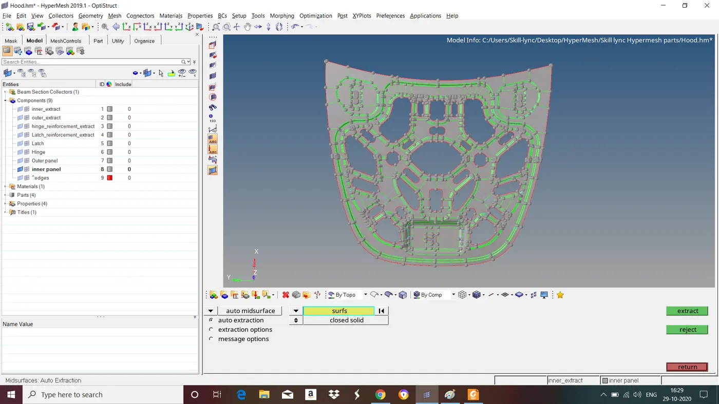
Fig : Midsurface of Inner panel.
Follow the same steps to extract midsurface from all the components.
4. Assign Thickness
After extracting midsurface we have to assign property,material and thickness for that midsurface.
To assign matarial goto tab bar right click>create>material>select newly created material and right click>edit>Give material and its properties>close.
To assign property goto tab bar right click>create>property>select newly created property and right click>edit>give thickness and material>close.
Now goto tab bar in components select midsurface component right click>edit>assign created property>close.
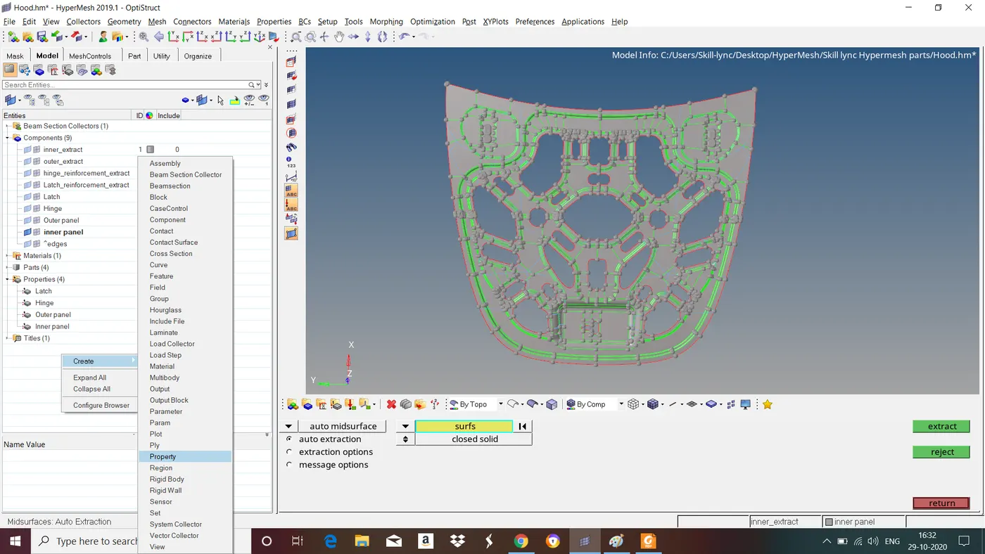
Fig : Assigning material, property and thickness.
5.Meshing
A mesh is network that is formed of cells and points. It can have almost any shape in any size and is used to solve partial differential equations. Each cell of the mesh represents an individual solution of the equation which, when combined for the wholw network, results in a solution for the entire mesh.
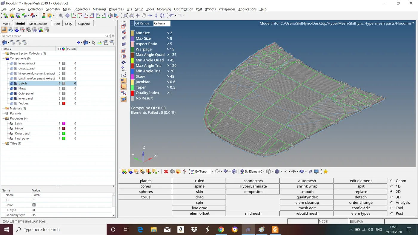
Before proceeding to meshing Give element length and quality criteria. To do this goto 2D>quality index>give quality criteria>close
S.N Quality Criteria Value
1 Aspect Ratio 5
2 Skewness 45
3 Warping 15
4 Taper 0.5
5 Min. Length 2mm
6 Max. Length 8mm
7 Min angle Quad 45
8 Max angle Quad 135
9 Min angle Tria 20
10 Max angle Tria 120
11 Tria % 10
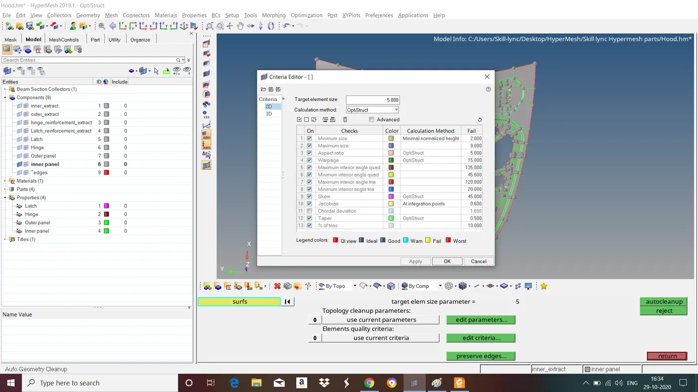
Fig : Giving target element length and mesh quality criteria.
Give washer splits for holes to get good mesh flow.
Now start meshing surface by surface to get better mesh flow. To do this goto automesh>select the surface>mesh.
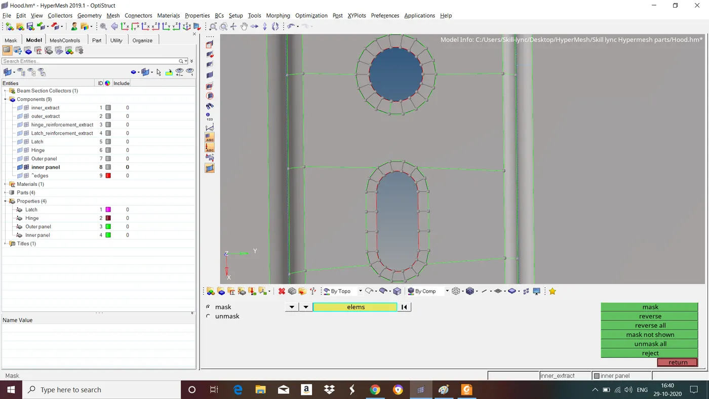
Fig : meshing
select element type based on surface to get good mesh flow. Use mixed type mesh for irregular shaped surfaces, use quads mesh for rectangular and square shaped surfaces.
Avoid :
- Trias in corner or edges.
- Opposite trias.
- Back to back trias.
- No trias in fillets or hemmings
- Rotational quads
- Trias share a boundary with feature line
For symmetry components meshing of one half of the component is enough another half we can mirror it by using reflect option. To do this Goto tool>reflect>select this axis that it shlould reflect to and base node>select the elements and duplicate it (Note : Dont duplicate more than once)>reflect.
After reflecting we have to combine the nodes at middle. To do this goto tool>edges>select the elements>preview equivalence>equivalence.
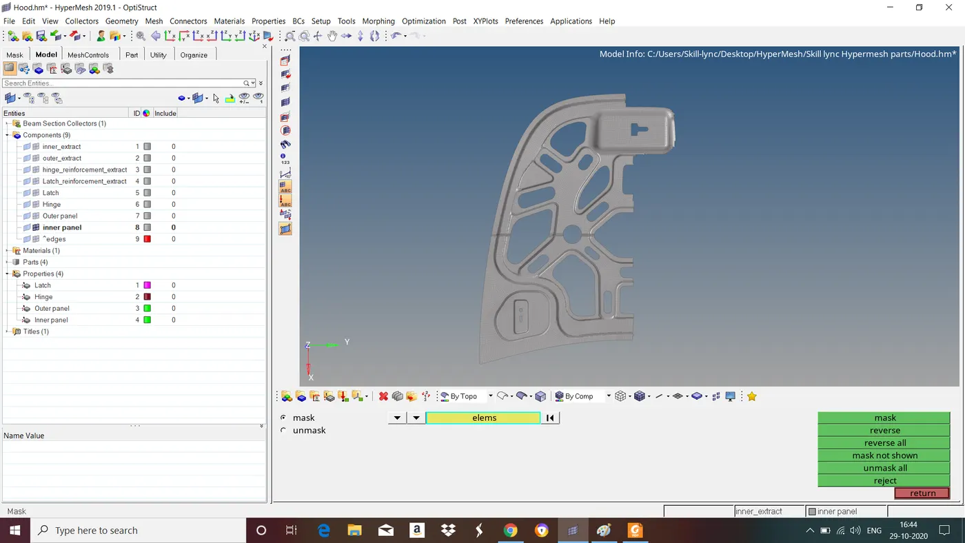
Fig : After meshing one half symmetry part of inner panel.
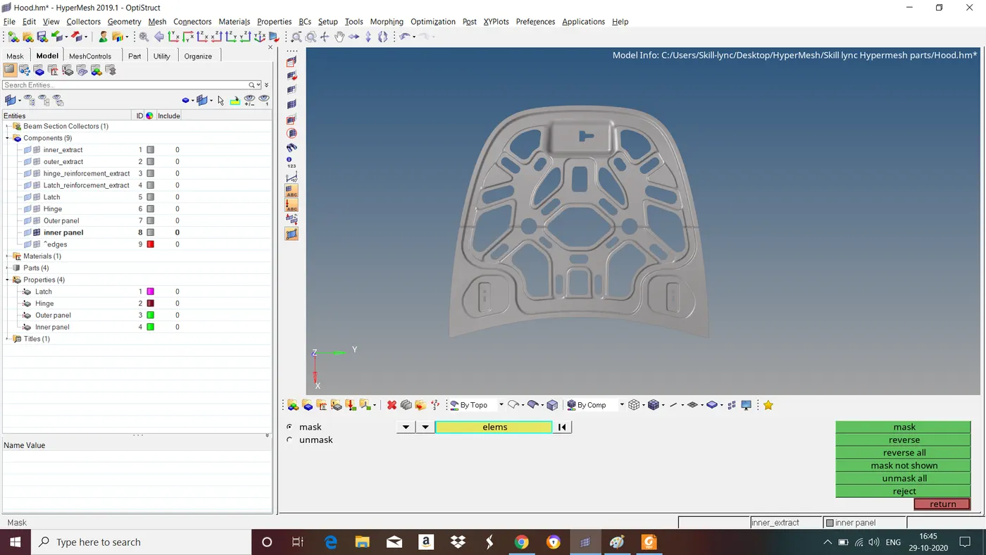
Fig : After mirroring and joining the nodes at middle.
Follow the same steps to mirror wherever necessary.
6. Remesh - Quality improvement
While meshing some of the elements may fail for some of quality criteria in compelex area this leads to poor mesh and results in inaccurate results. So we have to remesh on that areas to get good mesh flow.
To do this goto automesh>change to elements from dropdown menu>select the elements in that area>mesh.
Do this untill all failing elements are removed. If not we have do it by manually by using various options in Geom and tool panel.
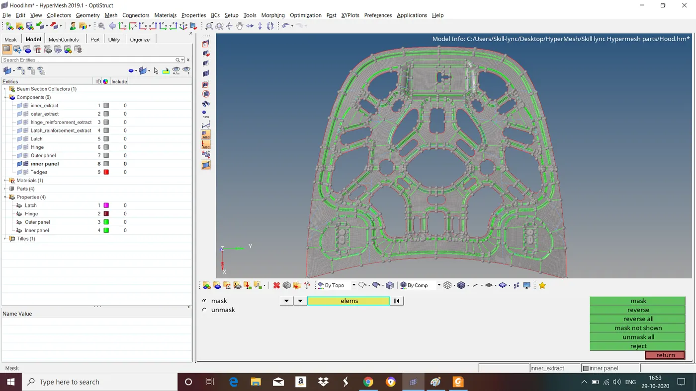
Inner panel :
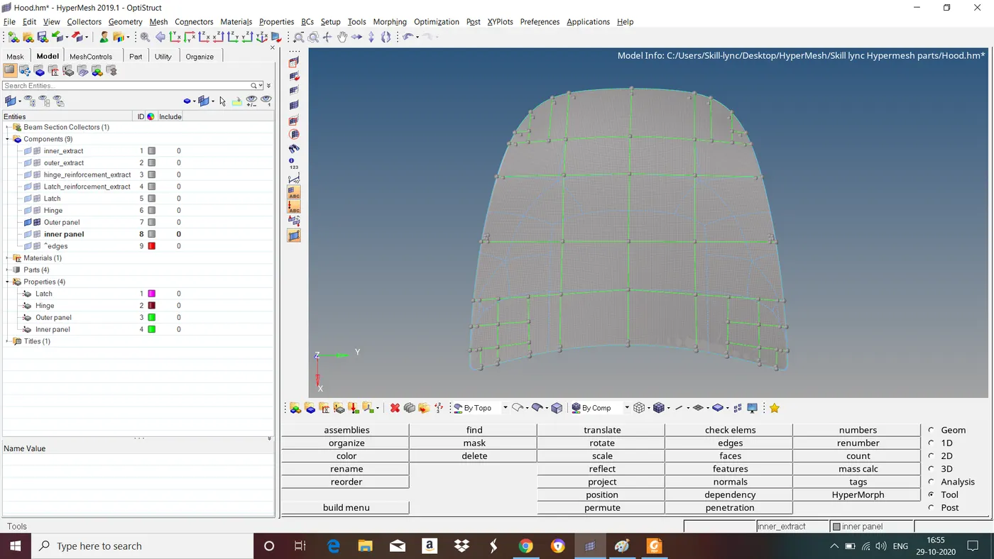
Outer panel :
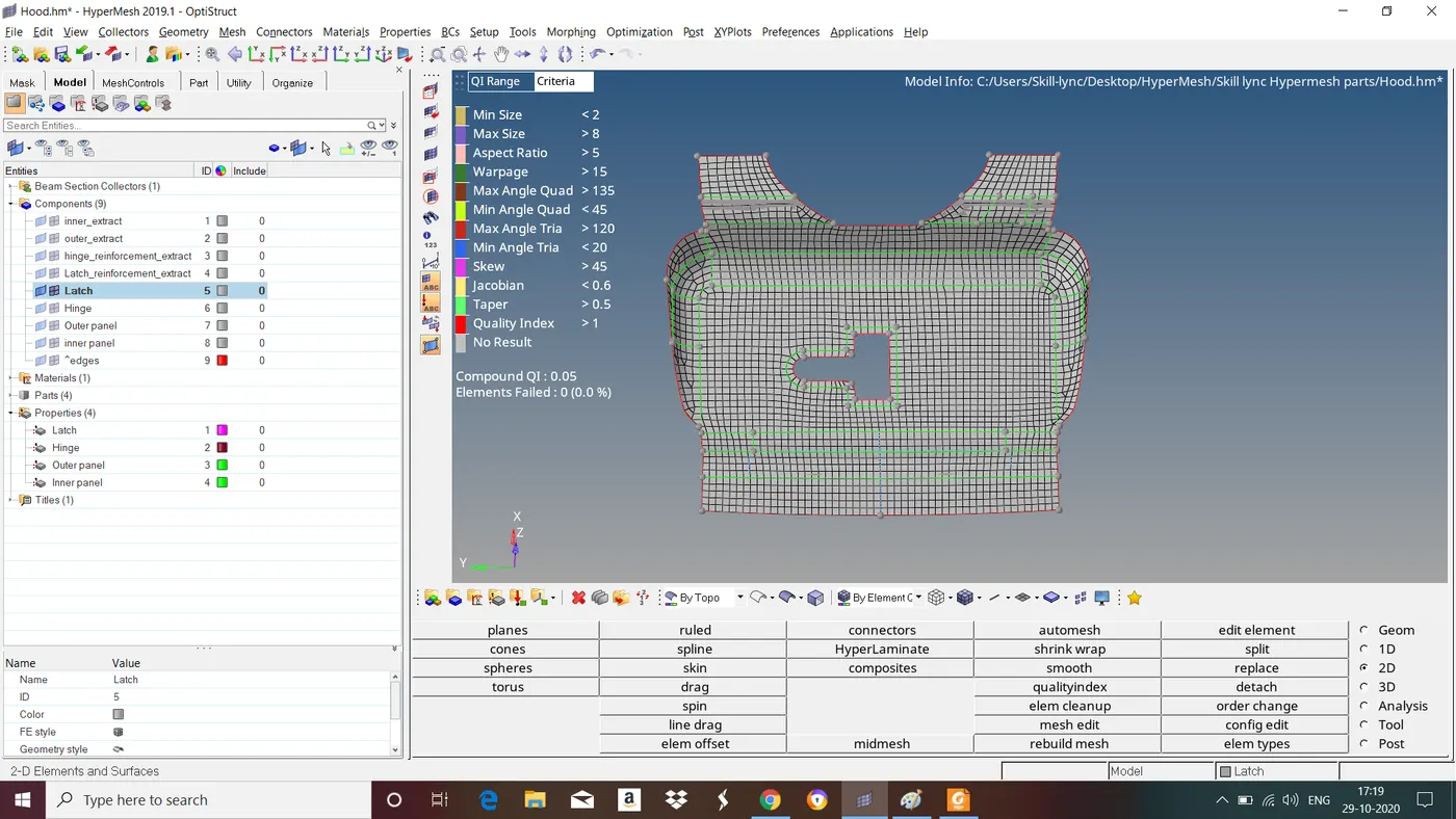
Latch :
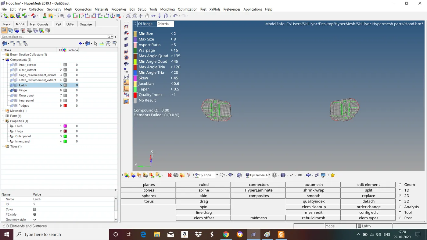
Hinges :
Final Model :
LEARNING OUTCOME :
- Performing the 2D Mesh.
- Correcting the mesh flow by using the different set of tools.
- Understanding the use of mesh quality.
- Exploring the tools that are used to clear the mesh quality errors.
CONCLUSION :
In this Challenge we have followed all the steps involved in topology cleanup, Midsurface extraction, assigning thickness and Meshing and obtained good mesh flow.