To Tetra Mesh for Rearview Mirror
AIM : To Tetra Mesh for Rearview Mirror.
PROCEDURE :
Step 1 : Import CAD Model to ANSA
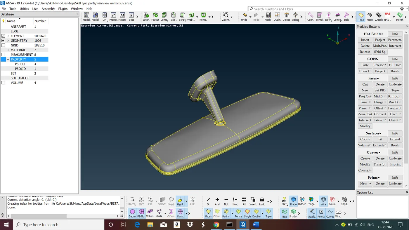
The CAD file is read and topology is applied.Notice that as by default the visibility mode of the model is set to ENT (Entity), We can see the red, yellow and blue CONS (Curves ON Surfaces).The coloring has to do with the connectivity of the faces.
- Red: a Single free edge CONS.
- Yellow: a Double CONS shared by two neighboringconnected Faces.
- Cyan(blue) : a Triple CONS shared by three or moreconnected Faces.
To make things clearer, we can activate and deactivate the visibility of each of the three types of CONS separately using the “Single”, “Double” and “Triple” flag buttons located in the FOCUS toolbar.
Step 2 : Geometry Cleanup
Before we start cleaning up the geometry of the model it is useful to perform a number of checks that are incorporated in ANSA. ANSA can identify and isolate on the screen the problematic areas that require the user’s attention. Click on the “Checks” button, located in the “Tools” toolbar on the top of the screen and select “Geometry”. The Checks Manager window opens. Here you can select the type of problems that may exist in the geometry of the model to be investigated by activating the corresponding flag in the lower part of the window. Keep the default options and click Execute.
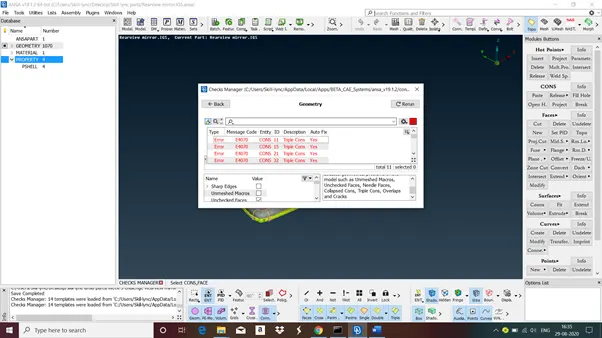
ANSA identifies the errors in the geometry of the model. We can highlight any of the problematic areas by left-clicking on it, or isolate it on the screen by right-clicking on it and selecting “Show only”. Depending on the type of the problem. ANSA also offers the option to automatically fix it.
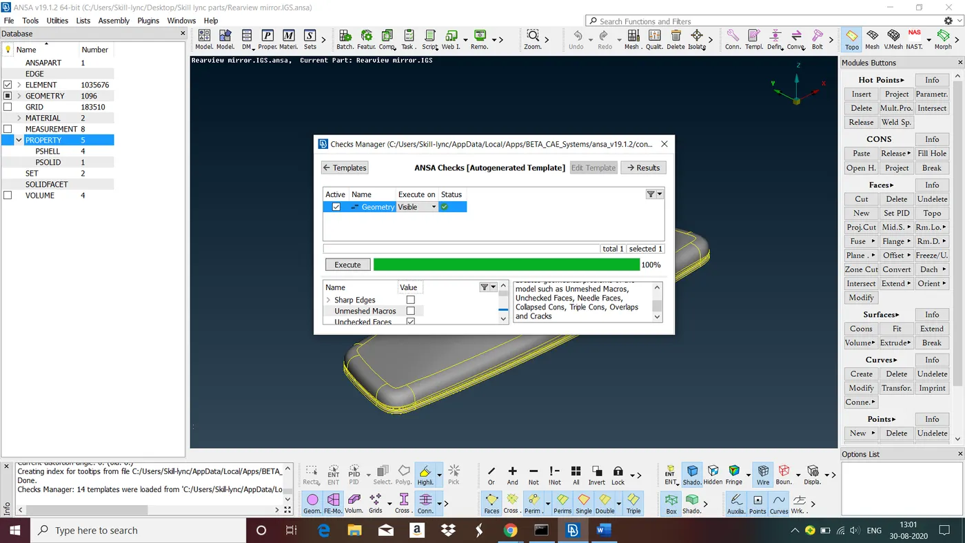
All the errors are fixed using auto fix. Now ANSA showing zero errors. Now we can move to meshing.
Step 3 : Give Element size, Mesh Parameters and Quality Criteria
- Element Size
Before proceeding to meshing, we should ensure that the correct element length assigned to all Perimeter Segments. To do that goto perimeters>Length>select the perimeters and give the length size.
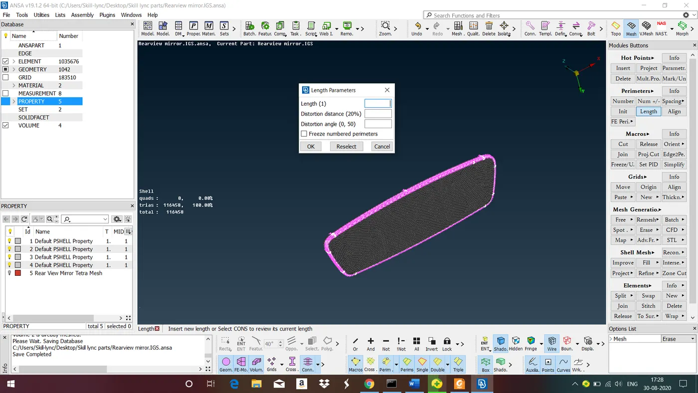
Above figure shows giving element length for the given model.
- Mesh Parameters
To do this Goto Utilities>mesh parameters>give mesh parameters>ok.
|
S .No |
Mesh Parameters |
Value |
|
1 |
Target length |
1 |
|
2 |
Minimum Length |
0.5 |
|
3 |
Maximum Length |
2 |
|
4 |
Mesh Type |
Ortho tria |
|
5 |
Element order |
1st order |
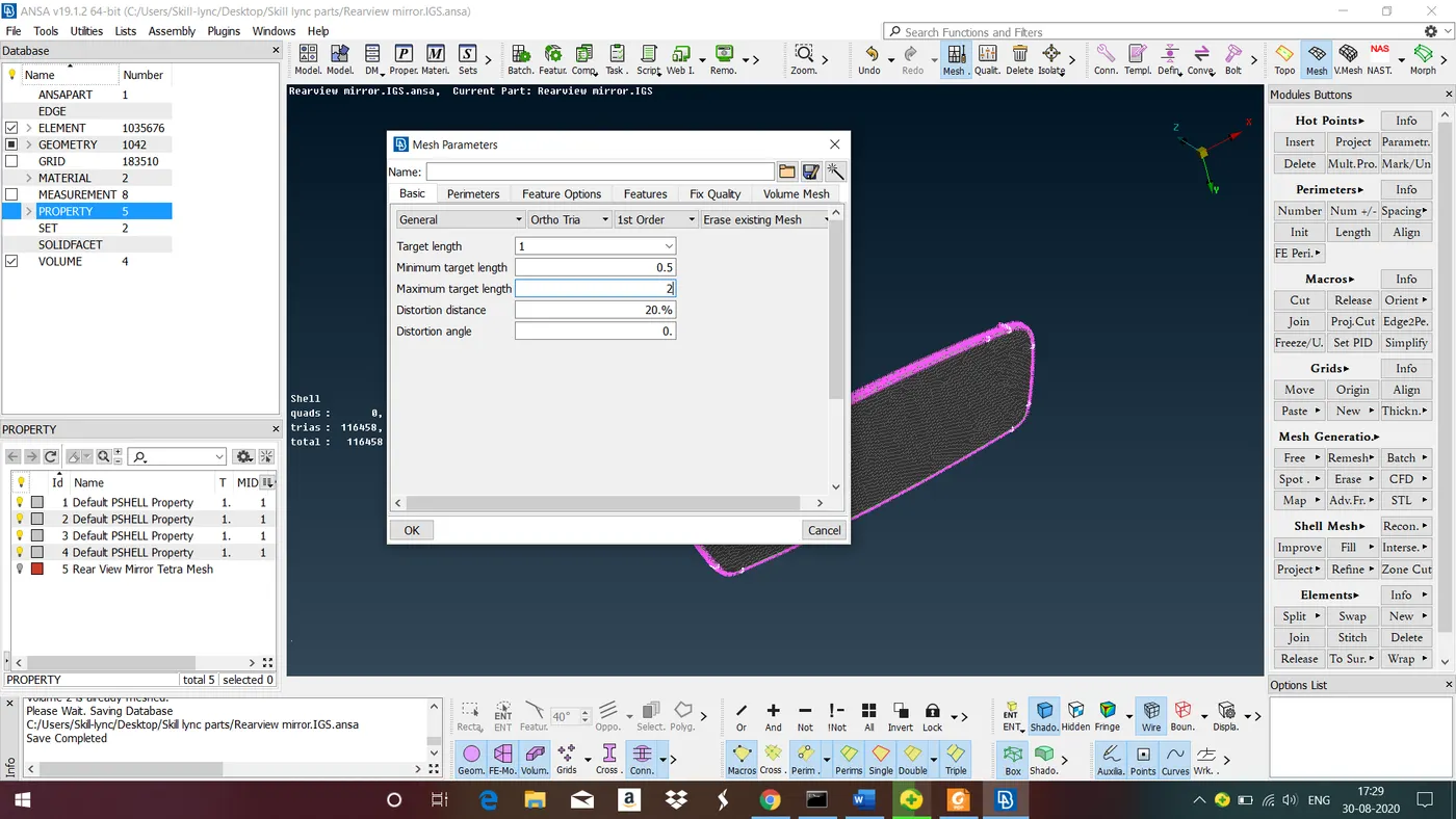
Figure shows giving mesh parameters.
- Quality Criteria
Reasons for giving Quality Criteria
-
The shape of Elements in FE Analysis may be distorted from their Ideal shapes when meshing the irregular or complex geometric shapes.
-
Every element is designed to work properly within a certain range of shape distortion. Exactly how much distortion and what type of distortion is allowed before an element degenerates depends on factors such as element type, numerical procedures used in the element design, and so forth.
- If the actual shape that the element assumes after mapping onto model geometry differs too much from the natural shape, the element becomes degenerated and produces erroneous results.
-
Each FE mesh should be run through an element quality check, and degenerated elements should be eliminated.
- In Tetra Meshing We only check for minimum length, Maximum length and Tet Collapse
|
S .No |
Quality Criteria |
Value |
|
1 |
Tet Collapse |
0.2 |
|
2 |
Minimum Length |
0.5 |
|
3 |
Maximum Length |
2 |
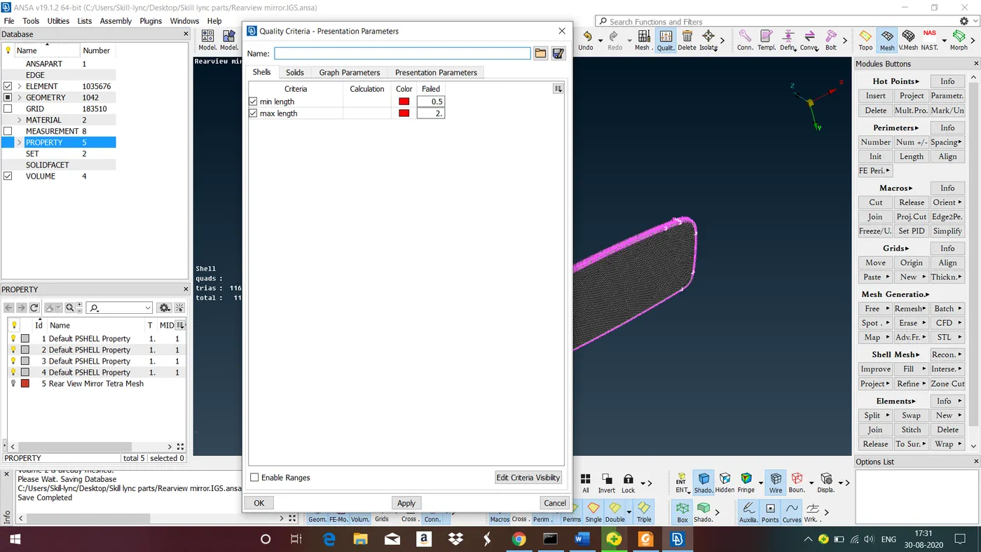
Figure shows Giving Quality criteria. Under shells select mini length and max length and give the values.
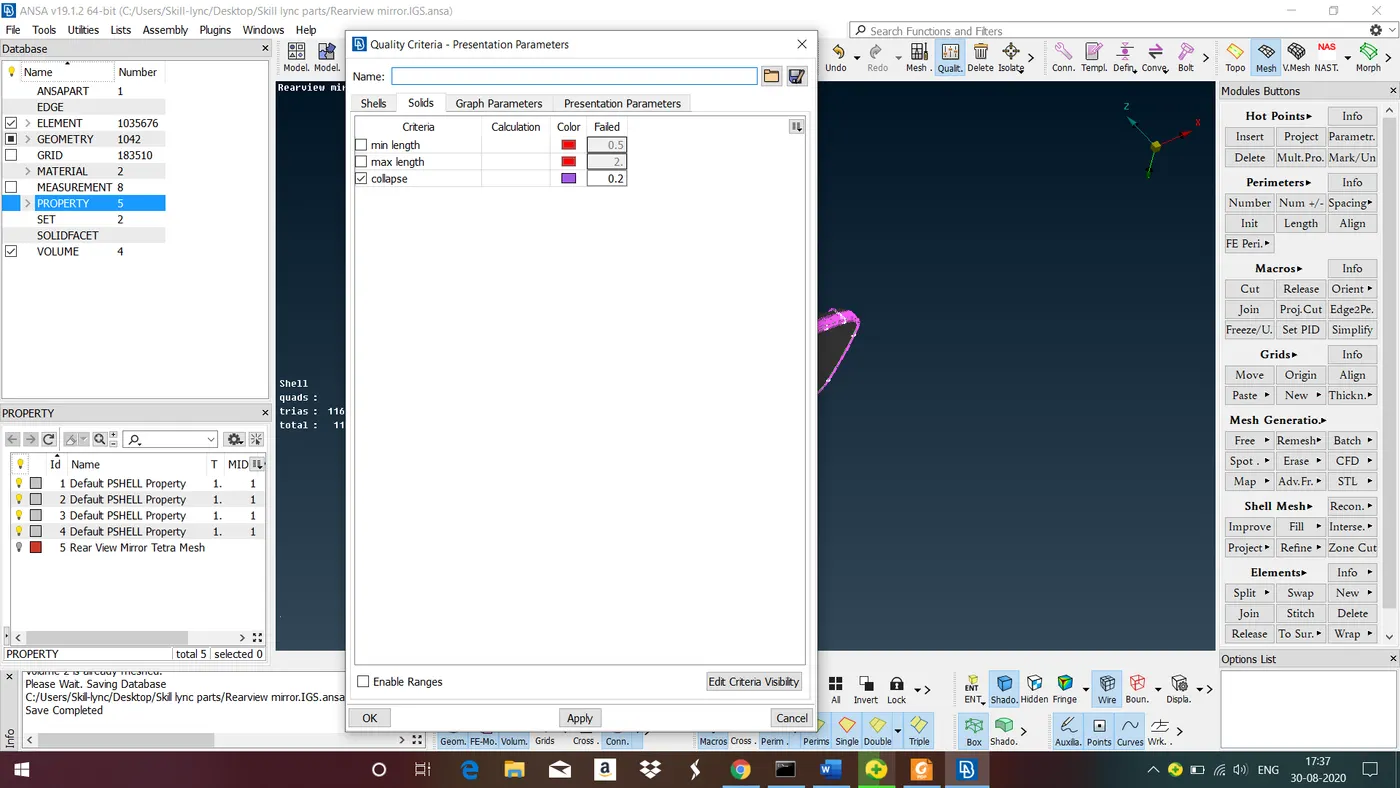
Under Solids select Collapse and give the value.
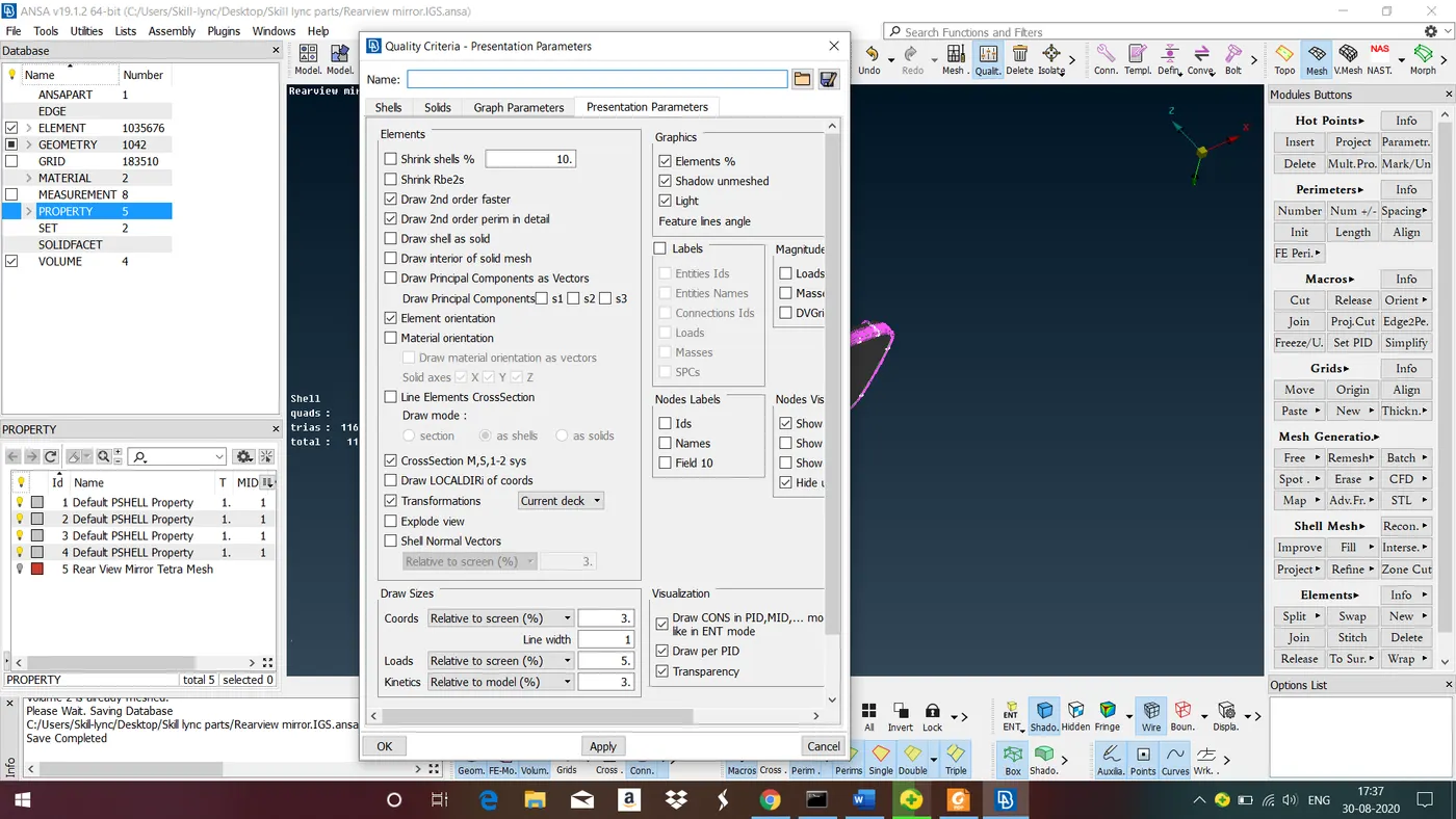
Figure shows Giving presentation parameters. Under presentation parameters under graphics tick 'Elements %'. Move the pointer to all 'Details' under 'Demand on Details Effect'
Step 4 : Generate the surface mesh
- For tetra mesh we use trias and ortho trias for mesh generation.
- For curved surfaces we use Ortho tria for mesh generation because it captures features more accurately than normal tria.
- For flat surfaces use normal tria for mesh generation.
- Generate a good quality of triangular surface mesh beacause these mesh only mapped into the volume while doing volume mesh.
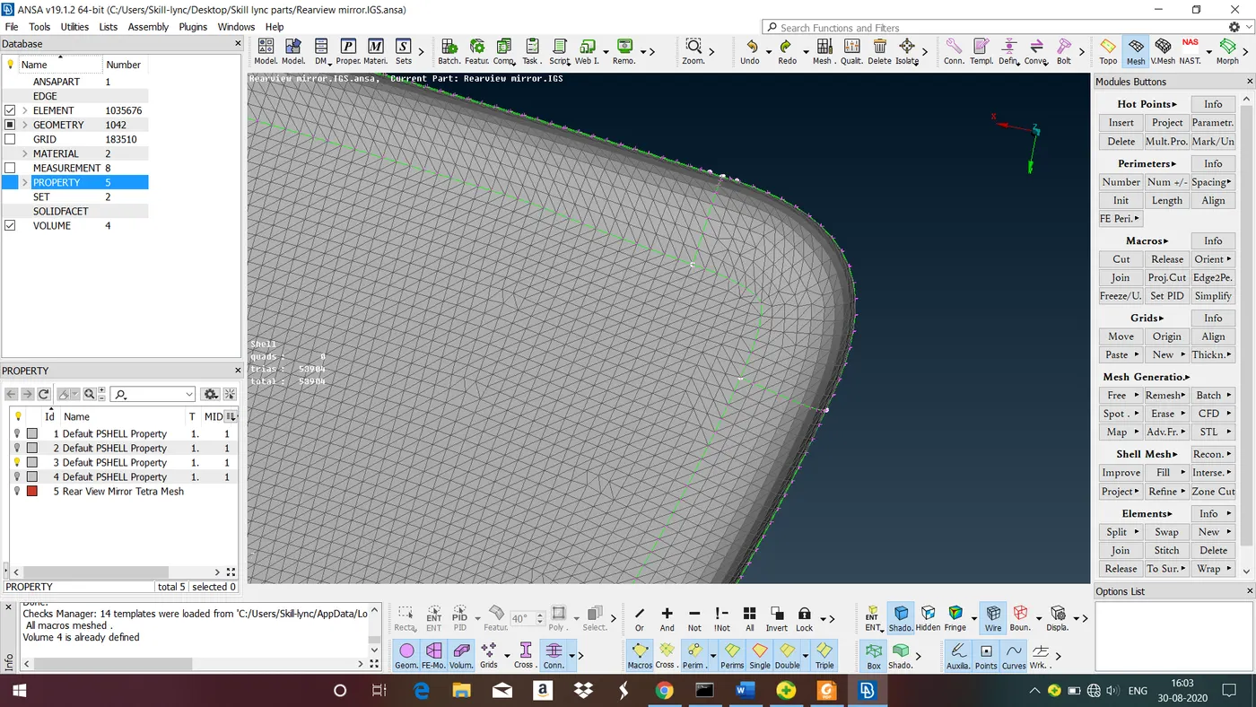
Above figure shows mesh generation using Ortho tria as element type in curved surfaces.
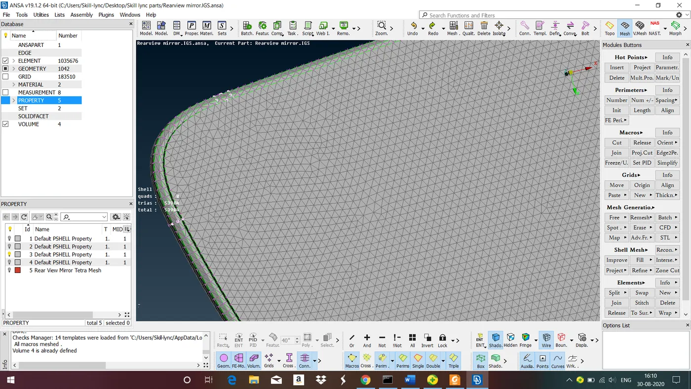
Above figure shows mesh generation using normal tria as element type in flat surface.
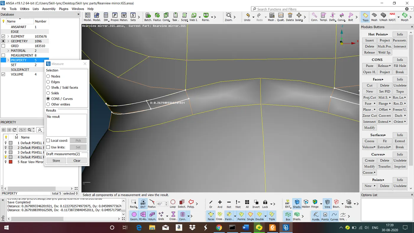
Above figure shows checking the length between the cons. Here distance between the cons is failing for minimum length criteria so now we have to do Defeaturing.
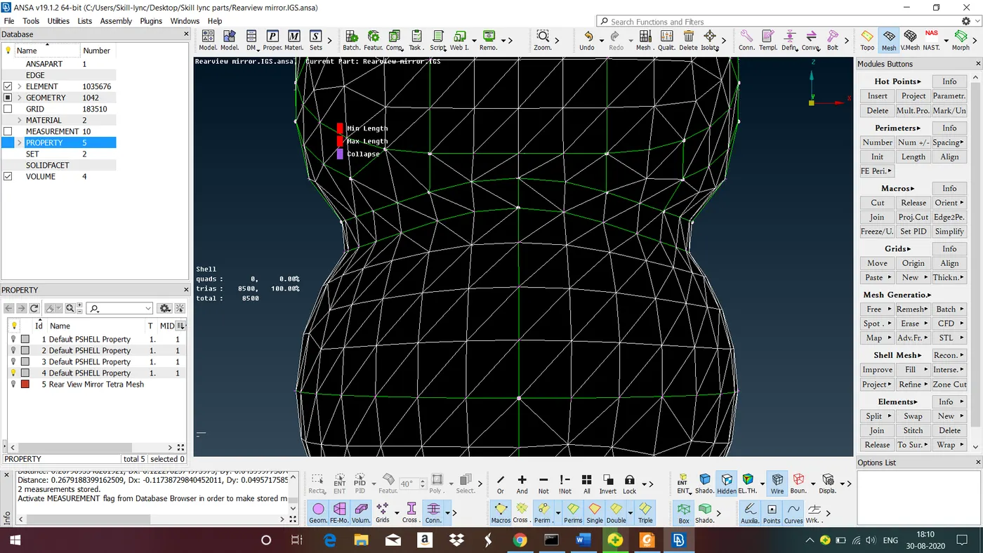
Above figure shows mesh is passing mininum length quality criteria after defeaturing.
Follow the same steps for all the surfaces for meshing.
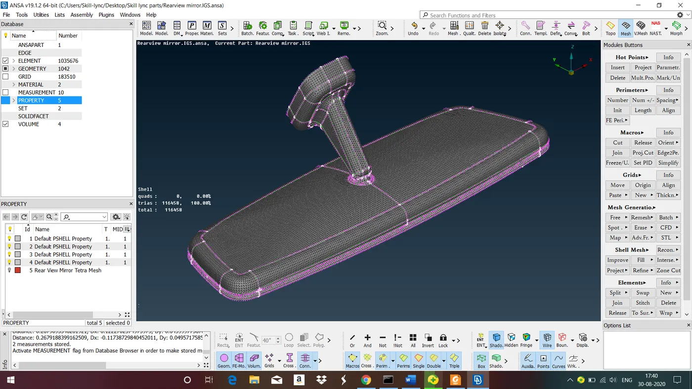
Above figure shows model after surface meshing with zero off elements.
Step 5 : Generate the Tetra Volume Mesh
In order to mesh the component with tetra elements you must first define the Volume entity.
- Activate the VOLUMEs>DEFINE function. Keep the Auto flag active in the Mode window.
- Left click on one of the Macros that form the volume.
- The Auto mode recognizes and selects all the Macros that form a closed volume. Press middle mouse button to accept.
- The Properties window appears so that you can assign a Property for the solid elements that will be generated.
- As there is no available Property in the list click on NEW to create one. A new Solid Property card appears. Click OK to accept the default values.
- Back to the Properties window, the newly created Property is highlighted in black. Double click on it in order to select it. The Part Manager appears, in order to allocate the Volume entity to a Part.
- Select NEW [PART] to create a new Part.A new empty Part appears in the Part Manager. Click on the name and change it to as 'Tetra Volume Mesh'. Then left click on the new part to place the Volume entity in it.
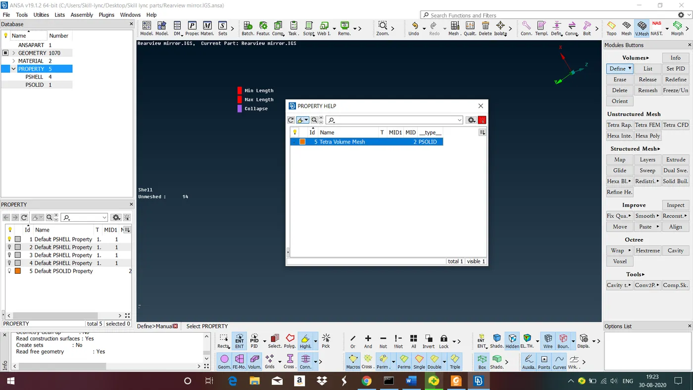
Above figure shows assigning a volume entity for a given model.
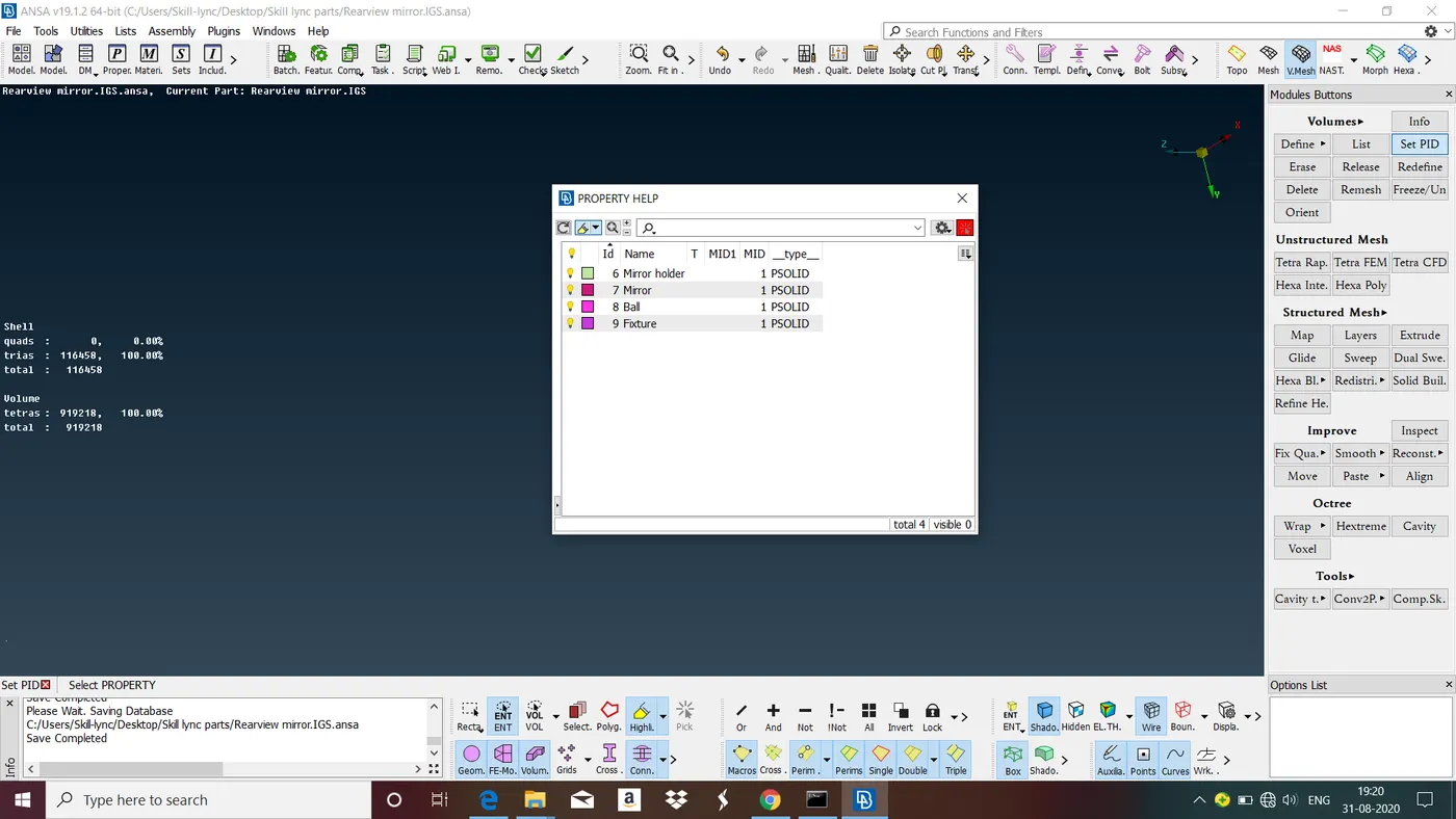
Above figure shows volume defined for all individual components.
To generate the volume mesh there are two methods
1. Goto unstructured mesh>select the meshing algorithm>select the volume>ok. Follow the same steps for all the volumes.
2. Goto list> select the volume and right click>remesh>select the meshing Algorithm>ok. Follow the same steps for all the volumes.
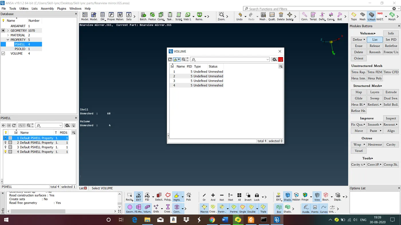
Above figure shows all the assigned volume showing in the list option.
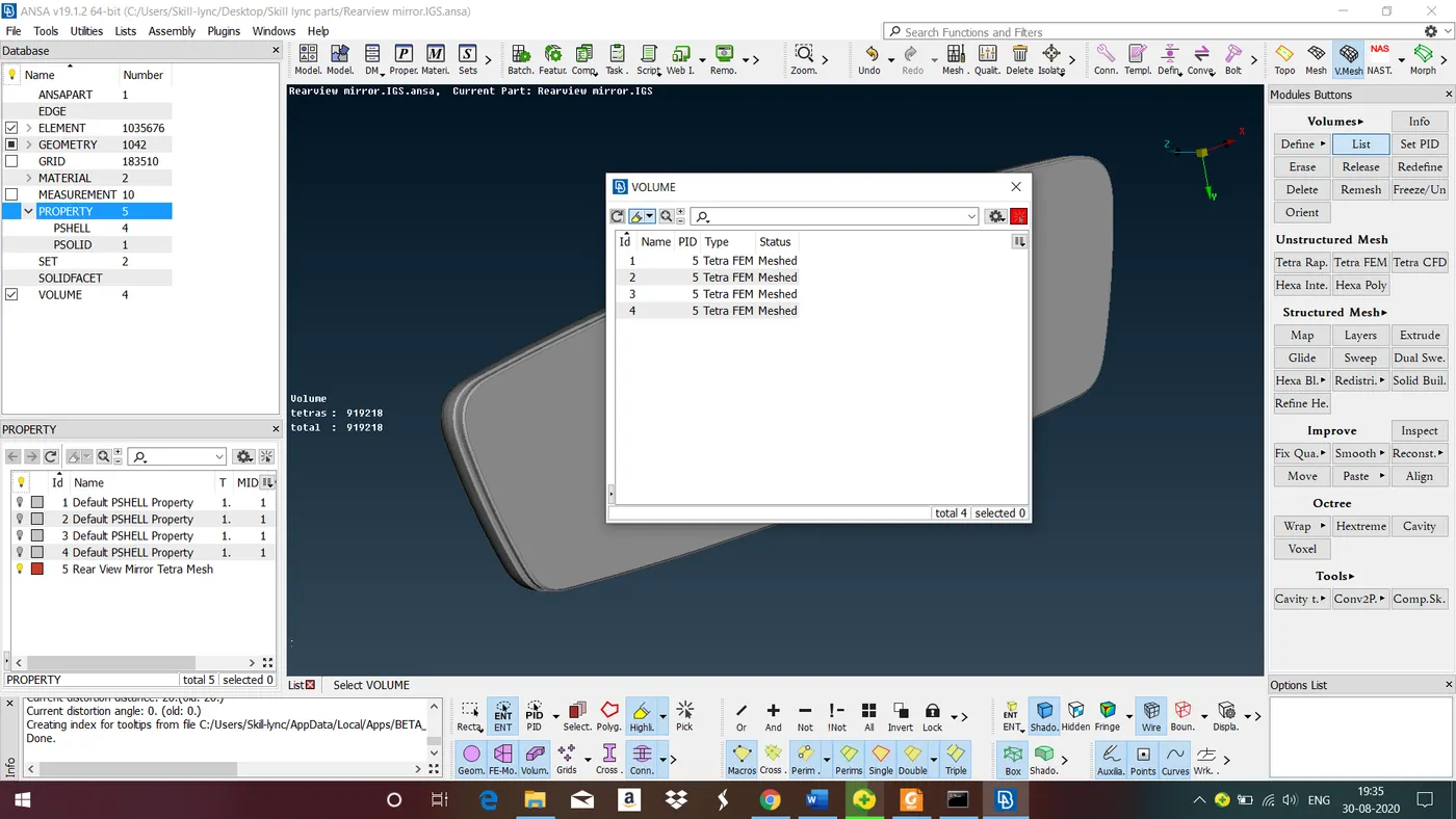
Above figure shows after volume meshing 'status' has changed 'meshed' and type changed to 'Tetra FEM' in the 'list' option.
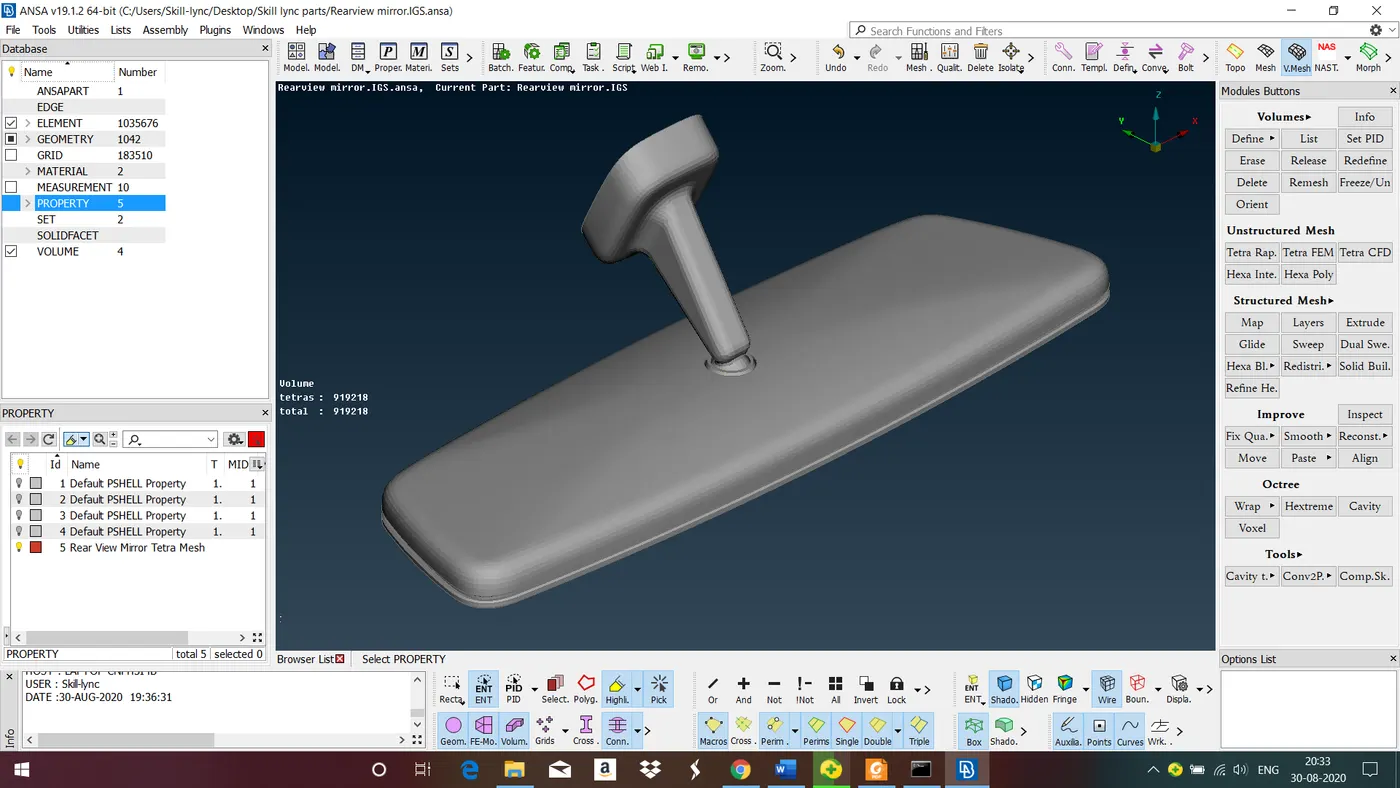
Above figure shows model after completing volume meshing. There are 116458 triangular elements are generated on the surface and 919218 tetra elements in the volume, as reported in the text legend on the bottom left of the display. De-activate the MACROs visibility flag to remove the Macro Areas from the view. Only the tetra volume elements remain visible.
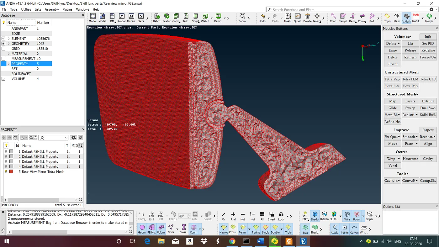
Above figure shows cross section of the model after volume meshing. as we can see only on the surface, mesh is structured and in the inside unstructred mesh has benn generated thats why tetra meshing is called as unstructured mesh.
LEARNING OUTCOME :
In this challenge we have learned all the steps involoved in tetra meshing for solid components.
CONCLUSION :
In this challenge we have followed all the steps from geometry cleanup to create Tetra volume mesh for the given component and obtained good mesh flow with zero errors.