To Create the Base Bracket Plastic component through the given Class-A surface
AIM: To Create the Base Bracket Plastic component through the given Class-A surface.
Introduction:
Heat Staking-
Heat staking is a pulsed heat process to join two or more parts out of which one at least is made of plastic. The process is to deform the plastic material using heat and force at a set process time. The bond is made by partially deforming the plastic part in order to fix the other.
Heat staking makes it easy tobond metal to plastic and is commonly used in high volume or low cost applications such as automotive and consumer appliances.
2 way and 4 way locators-
In any kind of assembly before fixing the part to the mating part we need to fix the position of the part with respect to the mating part. In these cases, We need to follow the 321 principle. Any part which has to be fixed during welding or machining process has to be fixed is having 12 Degrees of freedom i.e, Positive and negative Translation along X,Y,Z and Positive and negative Rotation along X,Y,Z.
Procedure:
1.Import the model to CATIA V5 workbench.
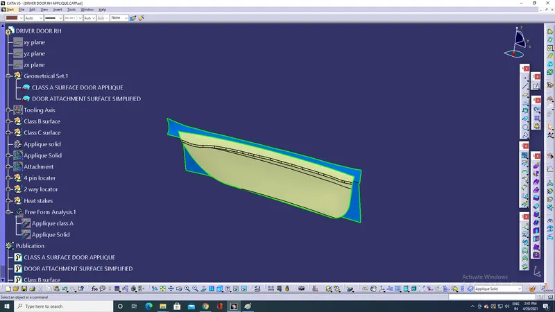
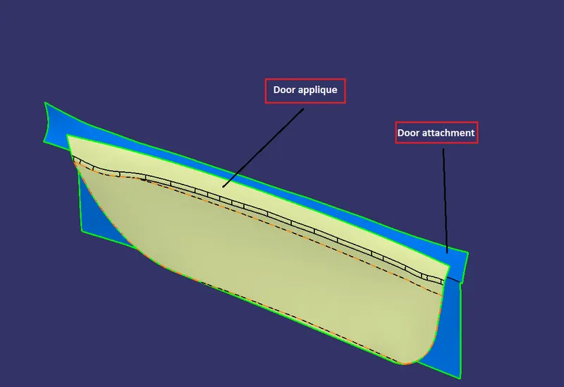
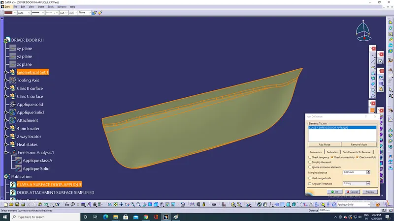
2.Check for connectivity of the surfaces.
Go to 'join'>tick 'check connectivity'>select the component.
3.Create the Tooling axis
Tooling direction is the direction in which mold opens or Core and Cavity opens.
- To create the tooling axis, we need proper orientation or view thatgives the correct featues and draft available in the component.
- So here the component view from the Z direction gives the proper view for the tool to see the features present in the geometry.
Procedure:
- Go to insert>analysis>Feature draft analysis.
- Select compass icon in draft analysis dialogue box and drag the compass and place it on class A surface
- Change the compass direction till all the surface of this portion passes for given draft angle.
- Lock the Compass direction.
- Go to 'lines'>select point and direction>select the point and direction as compass direction.
Draft Analysis:
Draft : Drafts are defined on molded parts to make them easier to remove from mold.
Major industries uses minimum draft angle of 3mm.
- Change the shading style to "shading with material".
- Go to insert>analysis>Feature draft analysis.
- Select compass icon in draft analysis dialogue box and drag the compass and place it on tooling axis and select lock draft direction option.
- Swith to quick analysis mode to see whether the surfaces are passed draft angles or not.
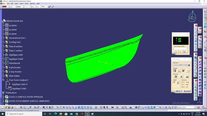
4.Create Class B surface
- Class B surface was created from the class A surface using Extract or MultiExtract option.
- Class B surface was offseted at a distance of 2.5mm thickness from the class A surface.
- Fillets were applied after necessary calculations.
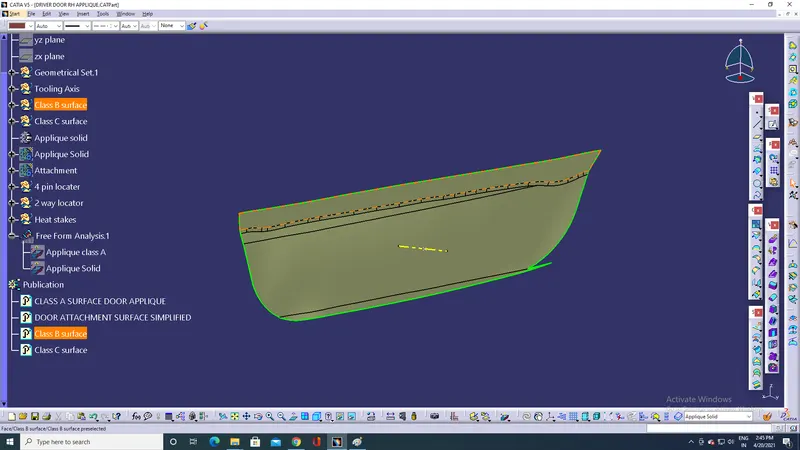
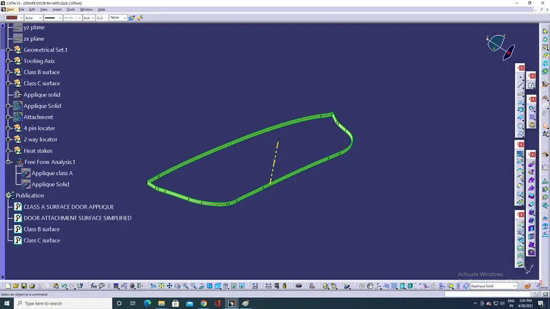
5.Create Class C surface
- Class C surface was swept along the boundary of Class A using Sweep option at an angle normal to the class A surface with respect to the tooling axis.
- A nominal draft angle of 3 degrees was applied.
- The Class C surface joined along with the class A surface.
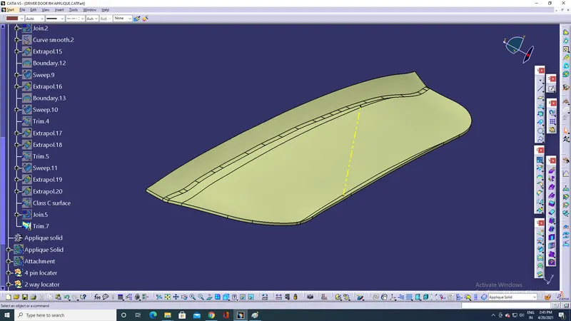
6.Create a closed surface
- Class A, B and C surfaces were joined together to form a single closed surface.
- Trim the Class B surface with the joined Class A and C surface to get closed surface.
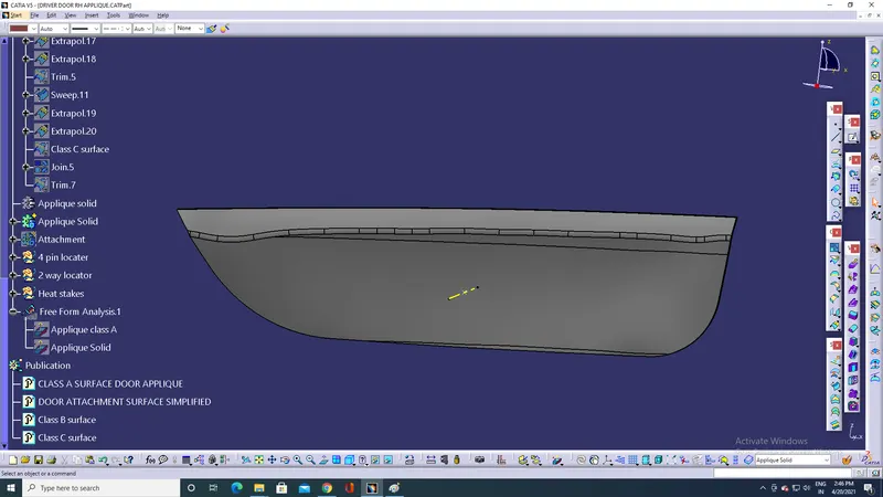
7.Create solid part
Convert closed surface into solid part by using closed option in part workbench.
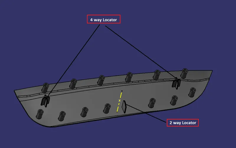
8.Create Locators:
- Create a loacator sketch on the Class B side of the solid part using positioned sketch and pad it.
- Create two 4 way locater at the ends and one 2 way locater at the middle. Height of the locaters should be the same for all.
- The clearence between the locator and hole is 0.1mm.
- Give draft angle of 0.5 deg and fillet of radius 0.25mm for all the surfaces.
- So that we can restrict the movement of the part along X,Z Translation and X,Y,Z Rotation.
- Translation along Y direction is restricted by heat staking.
9.Create Heat stakes:
- Create a heat stake sketch on the Class B side of the solid part using positioned sketch and pad it.
- The clearence between the heat stake and hole is 0.5mm.
- Give draft angle of 0.5 deg and fillet of radius 0.25mm for all the surfaces.
- Use Copy and translate option to create more heat stakes.
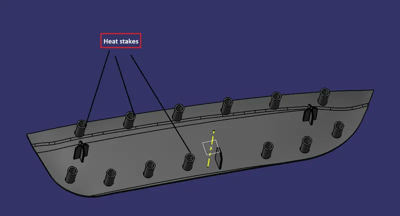
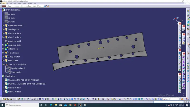
Fig: Door Attachment
10.Final model:
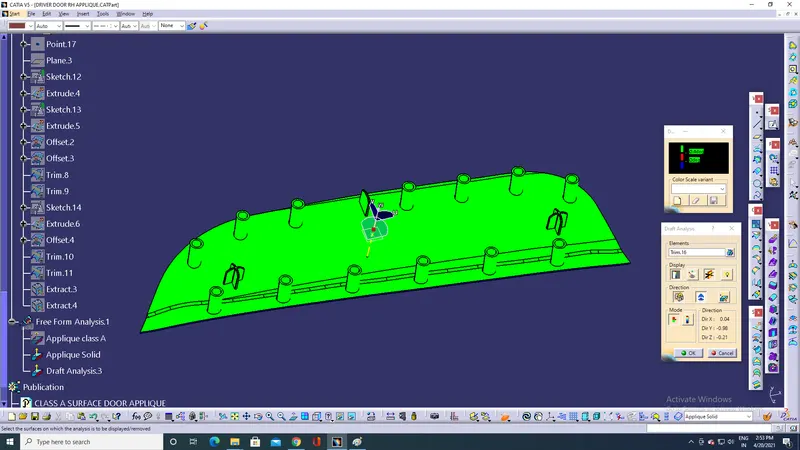
Fig: Draft analysis of final model.
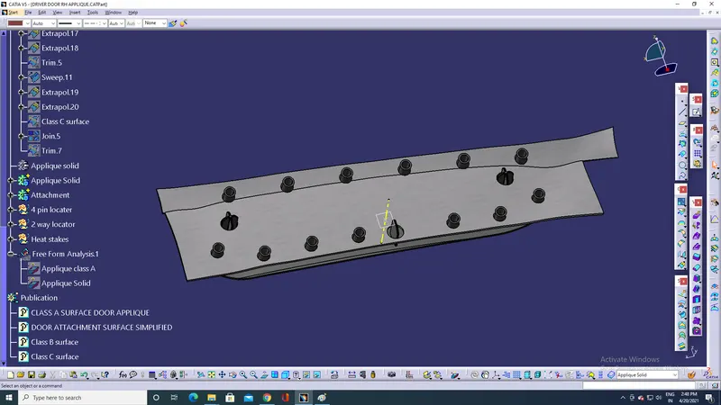
Fig: Final model.
CONCLUSION:
- Tooling axis created for the Class A surface of applique and draft analysis is perfomed for the same.
- Created Class B and Class C surface. Class A,B and C surface is joined to get closed surface and converted into solid part.
- Created 4 way, 2 way locator and Heat stakes.