Design of Core & Cavity using CATIA V5
AIM: To create Core and Cavity for the Switch Bezel.
Procedure:
Draft : Drafts are defined on molded parts to make them easier to remove from mold.
Drafting methods:
- By explicitly selecting the object.
- By selecting the neutral element
Major industries uses minimum draft angle of 3mm.
Procedure for draft analysis
- First we check the contuinity of the given Class A surface.
- Check the three directions(X,Y and Z) and decide which is the best possible direction to produce a mold.
- A fan with several drafted surfaces that is oriented in part location. That the draft analysis initially assumes a Z-axis direction.
- At Z-axis direction the faces are either positive or negative draft so the Z-axis we taken as dummy tooling axis. We need to create a perfect tooling axis.
Tooling Axis creation
Tooling axis: Direction in which mold opens or core and cavity opens.
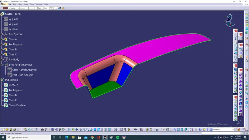
Fig: Given model.
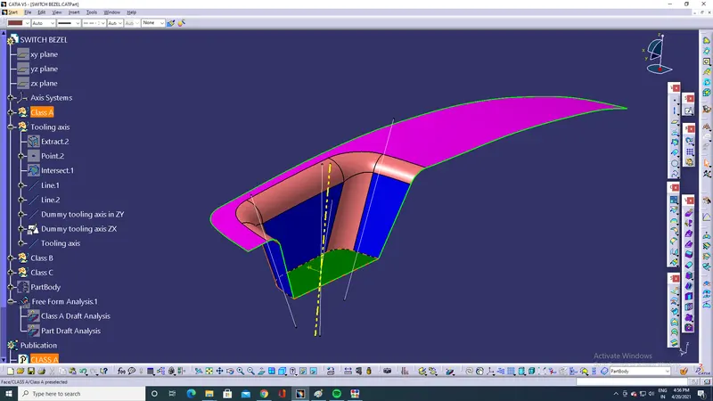
To create tooling axis by using Bisecting method
- The base surface is extracted.
- Then the center point is created using the point>on the surface at 0.
- Axis system is created at that point.
- Then the lines are created using 'lines'>'Point to point' along the slant surfaces.
- Bisecting line is created from these lines by using 'lines'>'Bisecting line'. This is the tooling axis for the part.
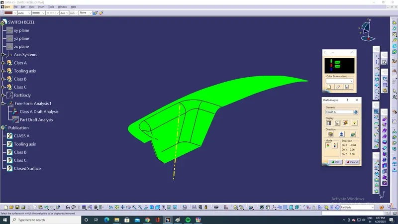
Lets do draft analysis
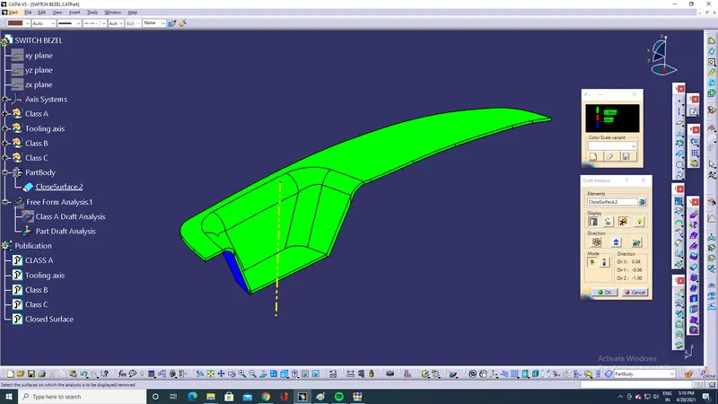
Change the shading style to "shading with material". Go to insert>analysis>Feature draft analysis. Select compass icon in draft analysis dialogue box and drag the compass and place it on tooling axis and select lock draft direction option. Swith to quick analysis mode to see whether the surfaces are passed draft angles or not.
Create Class B surface
- Class B surface was created from the class A surface using Extract or MultiExtract option.
- Class B surface was offseted at a distance of 2.5mm thickness from the class A surface.
- Fillets were applied after necessary calculations.
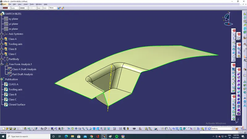
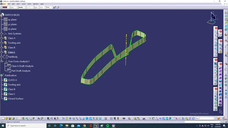
Create Class C surface
- Class C surface was swept along the boundary of Class A using Sweep option at an angle normal to the class A surface with respect to the tooling axis.
- A nominal draft angle of 3 degrees was applied.
- The Class C surface joined along withhe class A surface.
Go to swept>with respect to "line">"with draft direction" in subtype>select guide curve, draft direction, angle and length ok. Trim Extended surfaces.
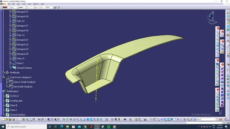
Create a closed surface
- Class A, B and C surfaces were joined together to form a single closed surface.
- Trim the Class B surface with the joined Class A and C surface to get closed surface.
Create a solid part from closed surface
Insert a part body and create a solid part using closed in part workbench.
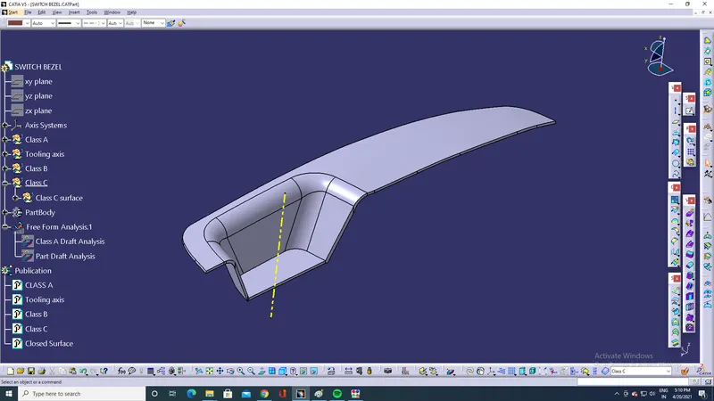
Final Model:
Draft anaysis of the solid part.
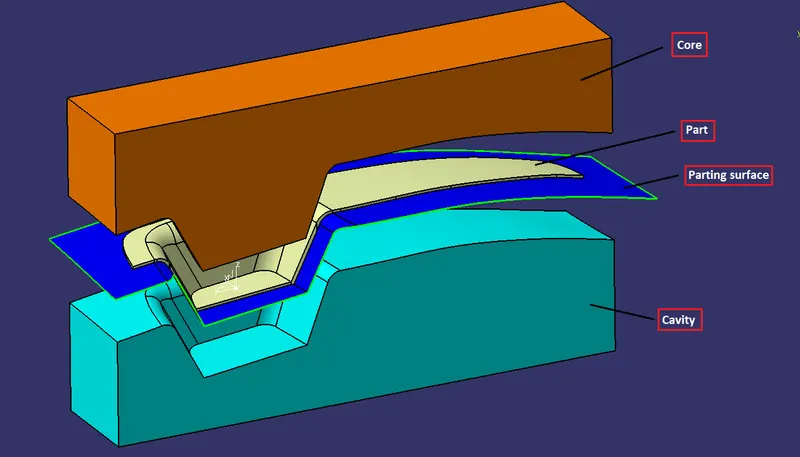
CORE AND CAVITY:
Fig:Core and Cavity
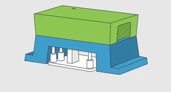
Fig:Core and Cavity in action
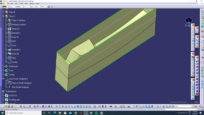
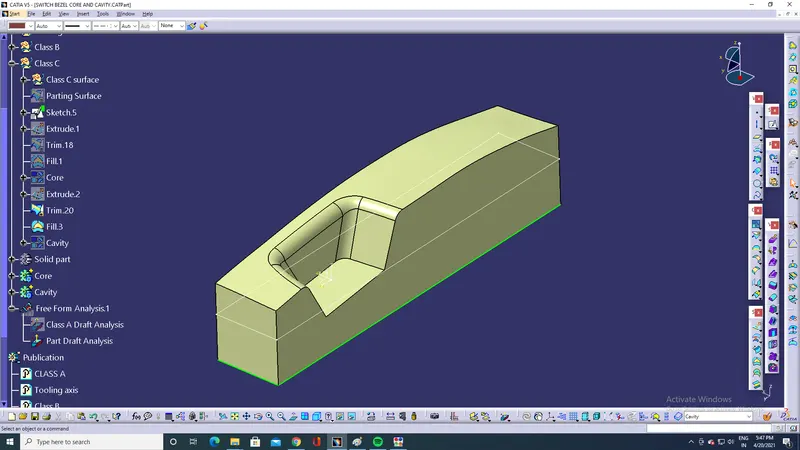
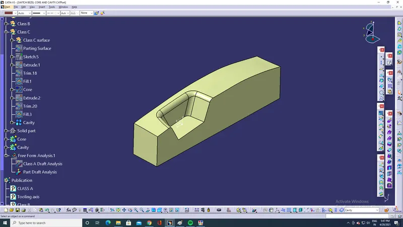
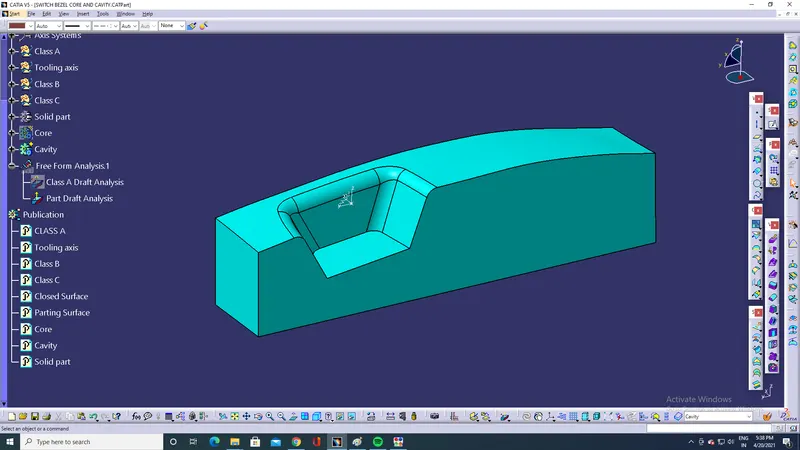
Cavity:
- Cavity and core are the moulding elements that give shape to the moulded part.
- Cavities are normally designed in the fixed half of the mould base, the injection side.
- Sometimes, however, cavities may be mounted on the moving side;
- Cavities are normally the "nice side" of the plastic part: well finished, without marks.
Create Cavity:
Core:
- Cores are normally designed on the moving half of the mould base. This is, the ejection side.
- In this side of the mould there is the ejection system of the injection moulding machine.
- This system connects to the ejector system of the mould.
- Cores are normally the hidden side of the plastic part. In cores, finishing doesn't normally need to be so good and ejector marks are normally accepted.
Create core
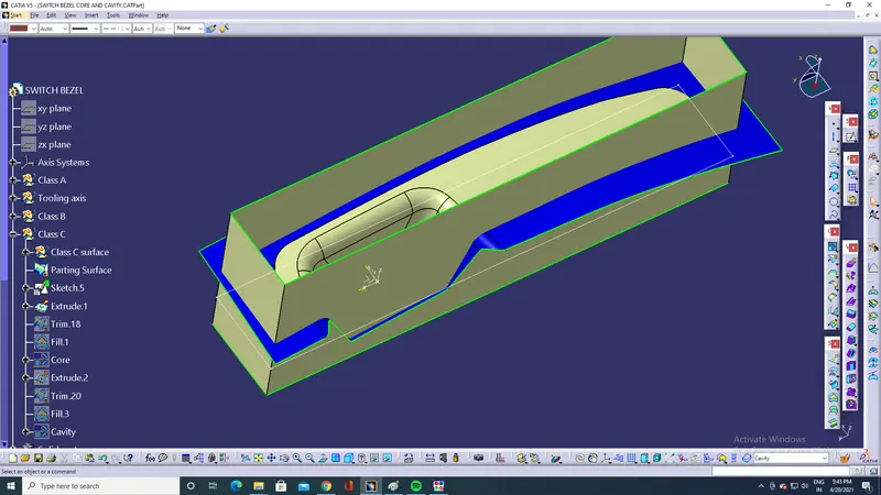
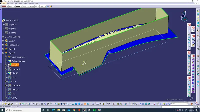
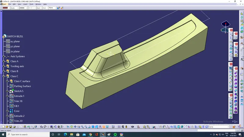
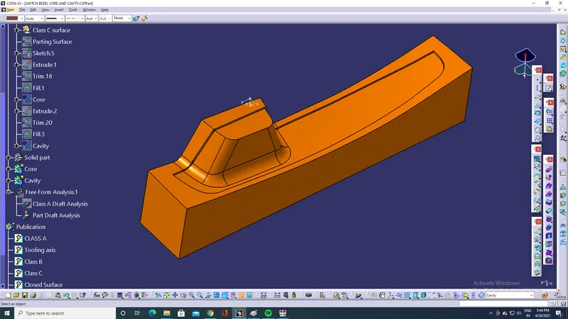
Core and Cavity for the part:
CONCLUSION:
- Created tooling axis for Class A surface and checked for draft for the same.
- Created Class B and Class C surface and Joined Class A, B and C surface and Converted into Solid Part.
- Draft analysis is performed for solid part.
- Created Core and Cavity for the part.