To Connect Different Parts of the Automotive Rear Door by Using Suitable Connectors.
AIM : To Connect Different Parts of the Automotive Rear Door by Using Suitable Connectors.
PROCEDURE :
STEP 1 : Input the file to ansa
goto file>input>nastran>select the file>ok.
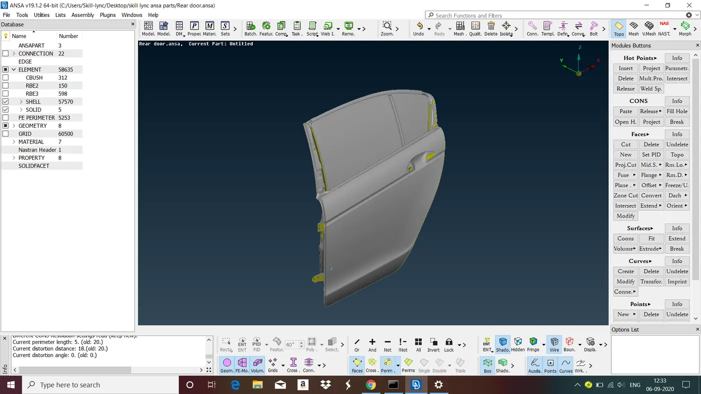
Fig : Rear Door
STEP 2 : Set separate PID for each parts
Goto property manager>right click select new>change the name as you want>ok>select the pid right click select apply>select the part that you want to create a PID>close property manager.
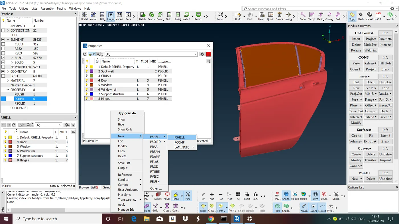
Fig : Creating new PID under property manager.
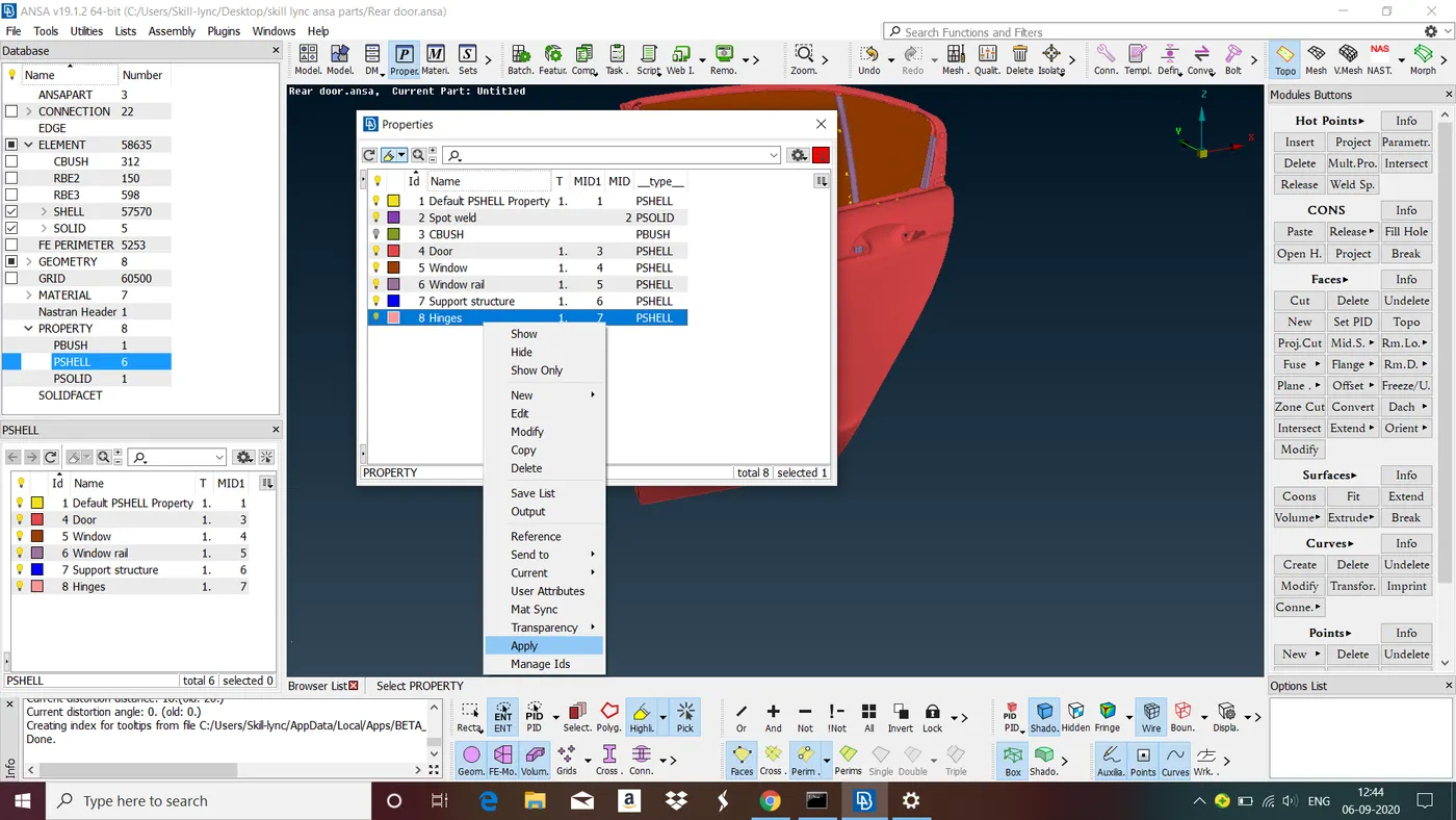
Fig : Selecting apply by right clicking on newly created PID.
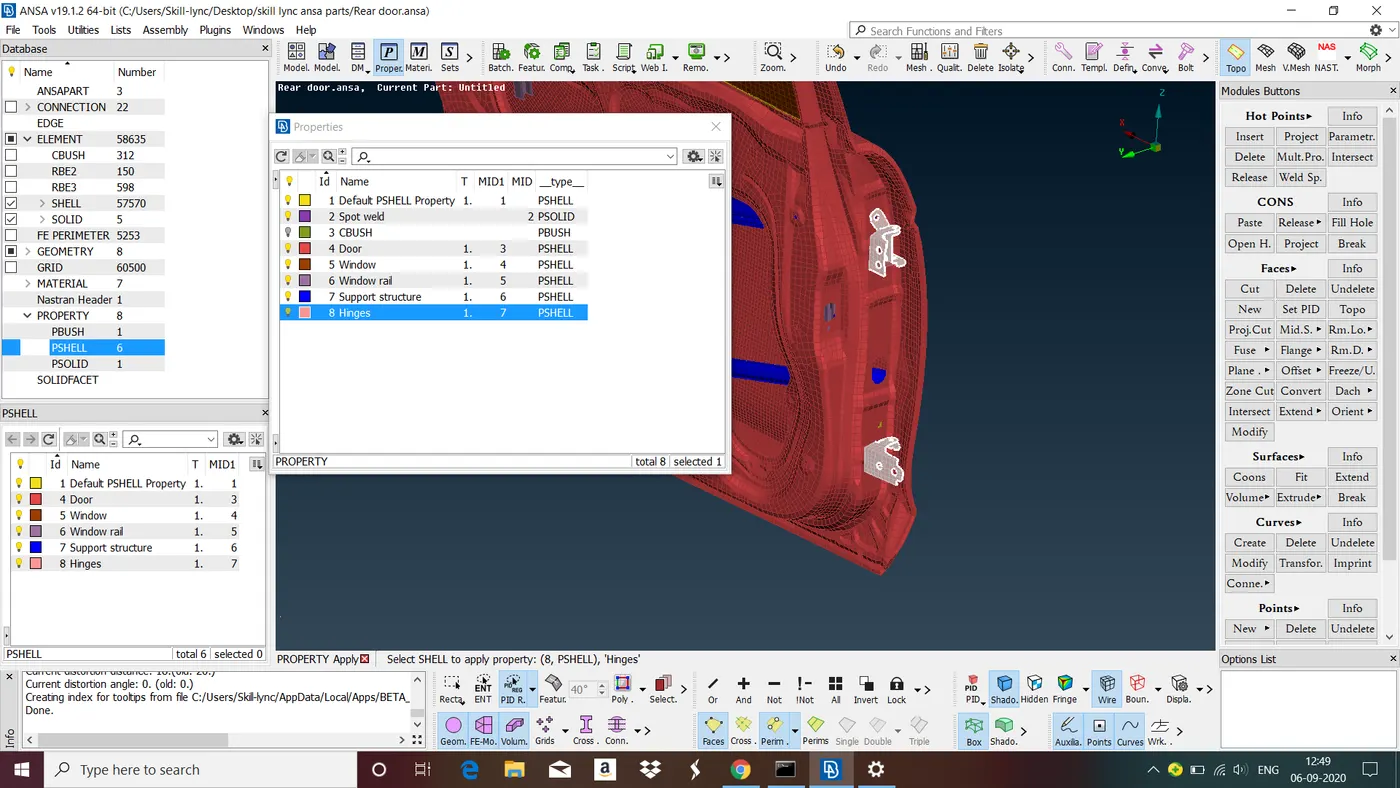
Fig : Selecting the parts for that PID. After selecting the parts middle click. Now PID is created for selected parts.
STEP 3 : CONNECTIONS
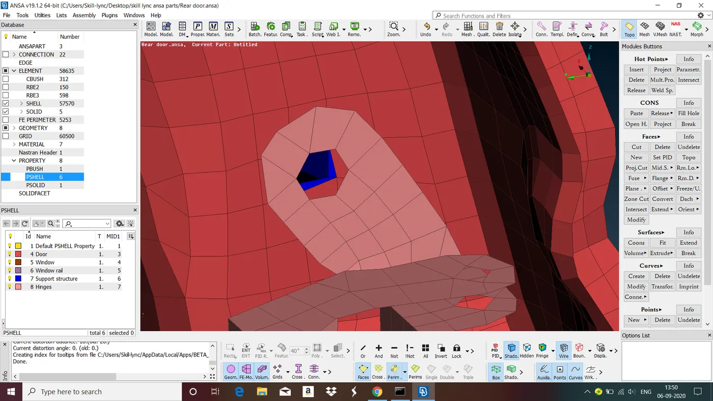
Fig : Hole provided for bolt connection between hinge and door frame
Steps to give Bolt Connections in ANSA
1. Create a COG point for the hole by goto points in topo>select COG>in COG select edges> now select edges of the hole middle click. point is created.
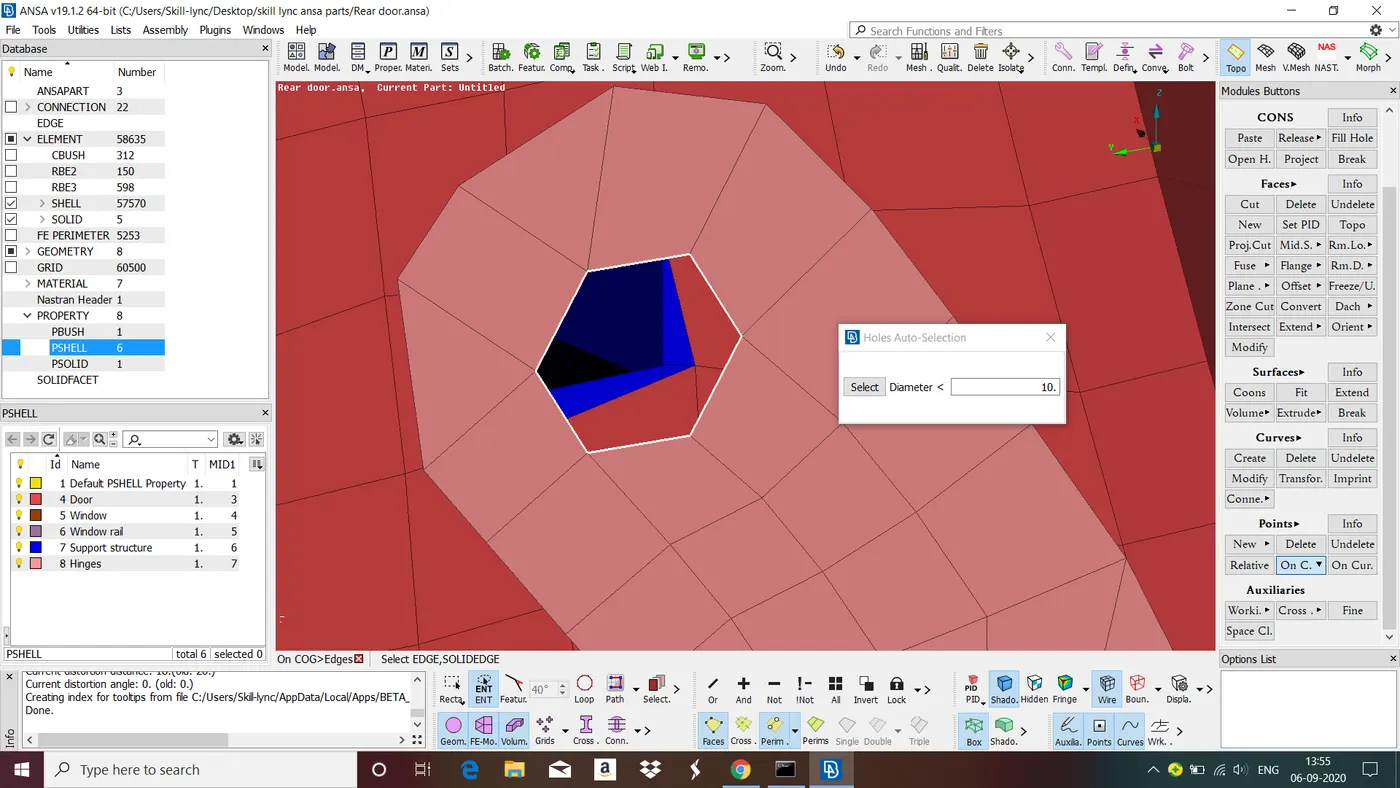
Fig : Creating a COG point for the hole.
2. Goto convert in assembly manager>select 3d points>select the point>slect bolt>. now point the point is converted to bolt point.
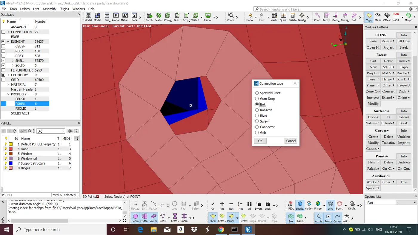
Fig : Converting 3D Point to Bolt point.
3. Goto connections manager in assembly manager>select the bolt point and middle click> select Bolt in FE Rep Type and give all the necessary parameters>apply> realize>close connection manager. Now the bolt connection is provided between the parts.
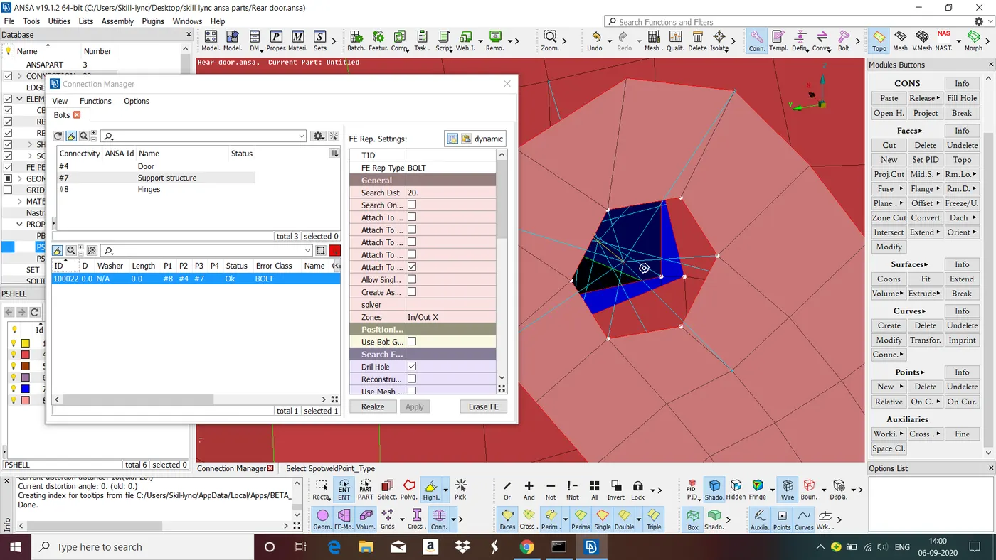
Fig : Bolt connection between hinge and door frame.
Follow the same steps to provide bolt connections wherever required.
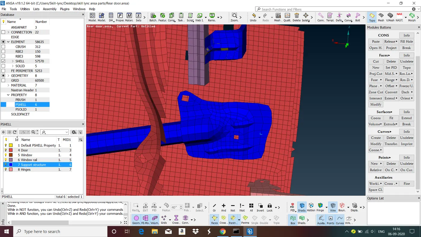 Fig : A rod is supported by a plate that is spot welded to the door structure.
Steps to give Spot Weld Connections in the ANSA
1. Create a point on the surface where spot weld is provided by goto points in topo>select COG>in COG select edges> now select edges of the spot weld surface middle click. Now point is created.
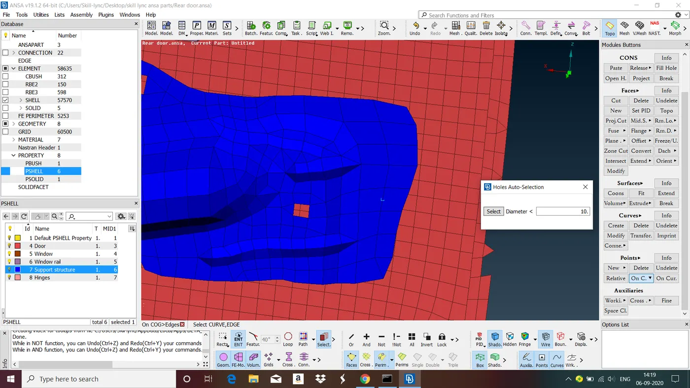
Fig : Creating a 3D Point.
2. Goto convert in assembly manager>select 3d points>select the point>slect spot weld point. Now point in converted to spot weld point.
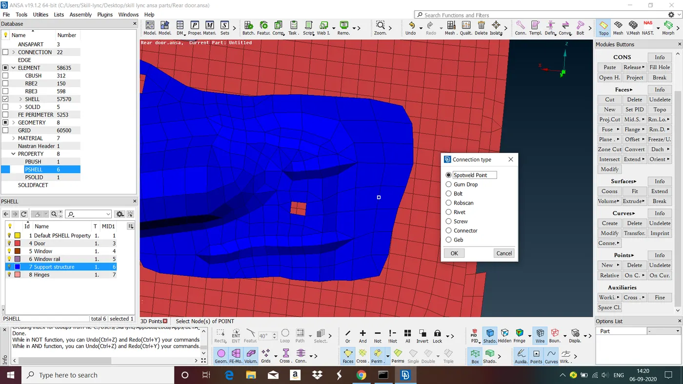
Fig : Converting 3D point to Spotweld Point.
3. Goto connections manager in assembly manager>select the spot weld point and middle click> select RBE3-HEXA-RBE3( for NVH analysis) in FE REP Type and give all the necessary parameter>apply> realize>close connection manager. Now the spot weld connection is provided between the parts.
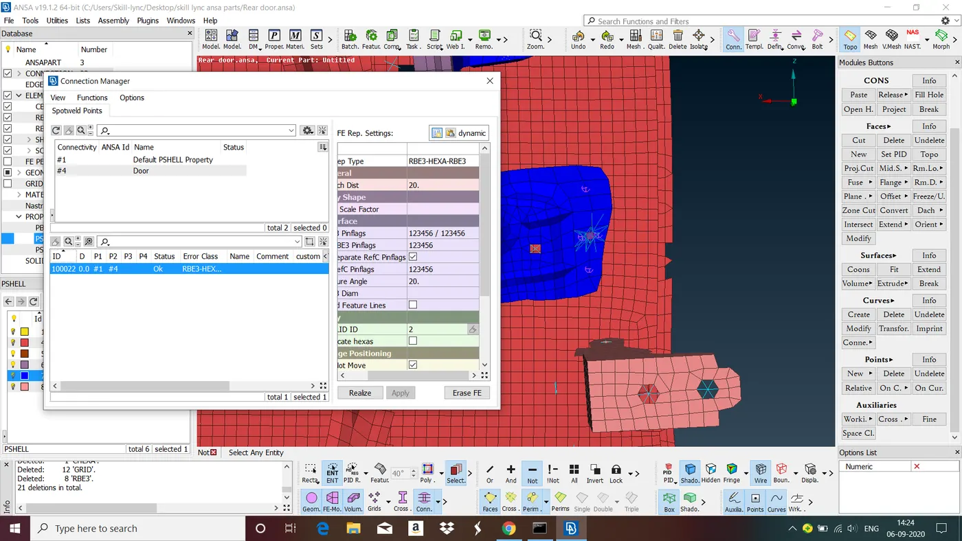
Fig : Spot weld Connection
Follow the same steps to provide spot weld connections wherever required.
To give connections between Window and Door
1. Create a curve on the perimeter of the window using Feat2curve.
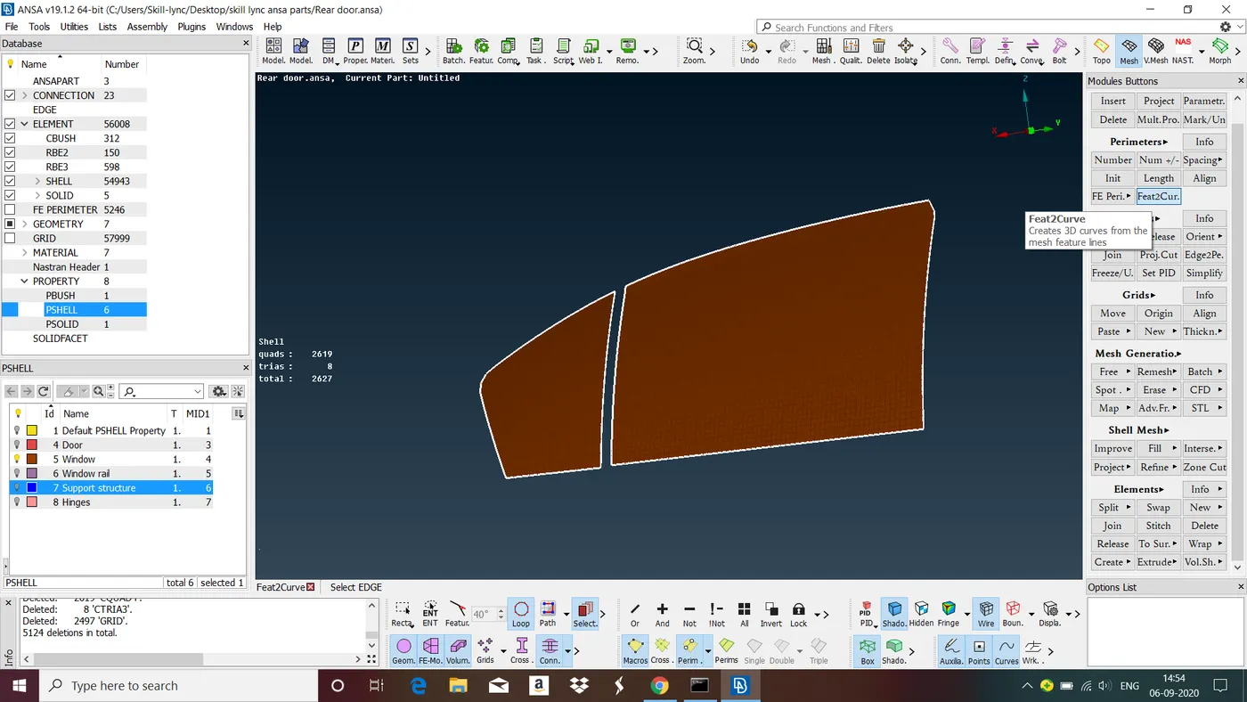
Fig : Creating Curves on the perimeter of the windows.
2. Convert the curve to spot weld line by using convert option.
Goto Convert>select 'curves'> select all the curves that you want to convert into spot line and middle click> select 'Spot Line'>ok.
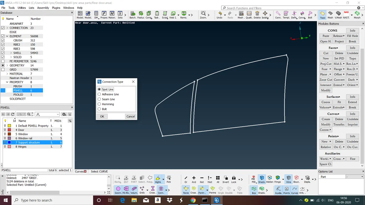
Fig : Converting curves into Spot Lines.
3. In connection manager use RBE3-CBUSH-RBE3 (for NVH analysis) as FE REP Type and give all the necessary parameters>Apply>Realise.
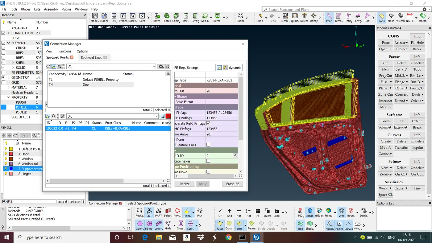
Fig : Window Door connection.
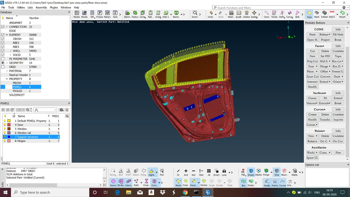
Fig: Final Model
LEARNING OUTCOME :
In this challenge we have learned modeling of Bolt, Weld and Window Door connections using various types of Connectors.
CONCLUSION :
In this challenge we have followed all steps involved in modeling of Bolt, Weld and Window Door connections.