To generate mid surface and meshing an automotive hood
AIM : To generate mid surface and meshing an automotive hood along with quality criteria and thickness assignment.
PROCEDURE :
Steps involved in to generate Mid Surface :
In Topo option
STEP 1 : Import CAD file to ANSA
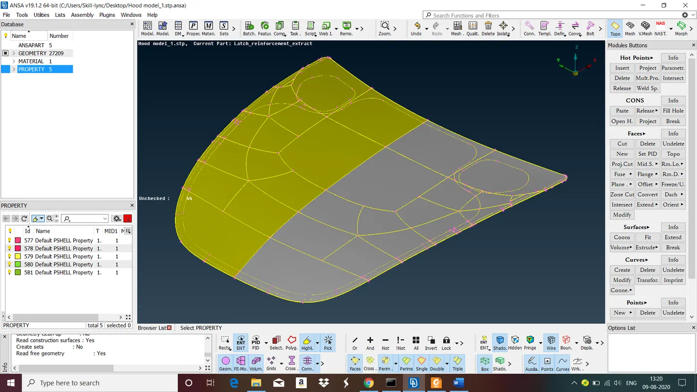
The CAD file is read and topology is applied. As by default we are in ENT (Entity) display mode, we see red, yellow and blue curves on surfaces which are called CONS. The coloring has to do with the connectivity of the faces. Red means a single free edge cons. Yellow means a double cons shared by two neighboring connected faces Blue curves means a triple cons shared by three or more connected faces. We can activate and deactivate the visibility of each of the three types of cons separately using the SINGLE, DOUBLE and TRIPLE flag buttons. De-activating here the DOUBLE flag shows only the free red and triple cyan CONS. Apart from the free edges of the sheet metal there are other gaps, untrimmed Faces etc. that must be corrected.
STEP 2 : Geometry Cleanup
Geometry cleanup means removing geomtrical errors which are present in the form of free edges, gaps, untrimmed faces, needle faces,etc from the given model. To check the geometry goto Checks>Geometry>select all entities> execute.
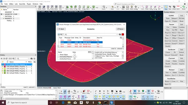
There are 44 errors present in the given model. We can fix it manually but it takes more time. Ansa provides a option called FIX which automatically fix errors present in model by itself to do that, select all errors>right click select Fix. Now all errors present in the model is fixed.
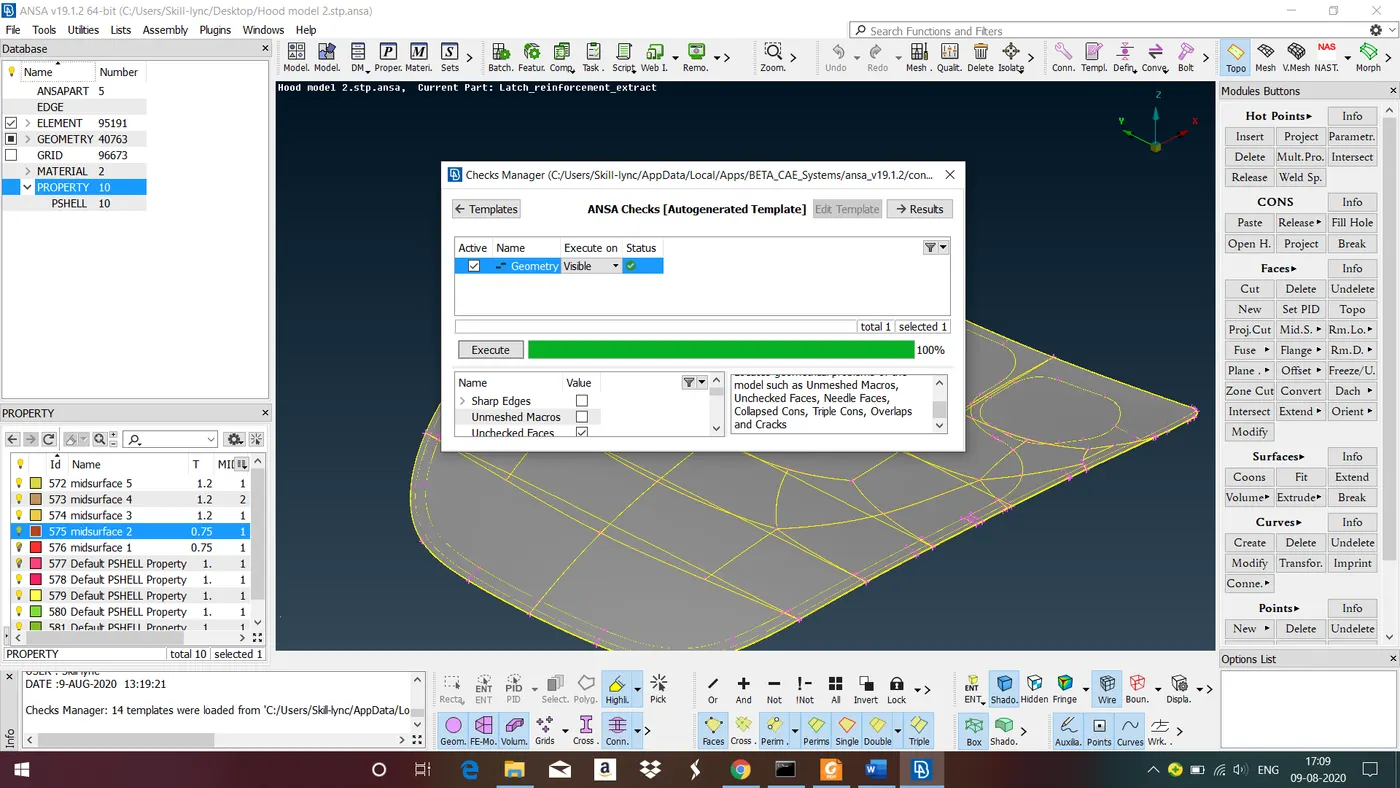
The above figure shows model after geometry cleanup showing 0 errors.
STEP 3 : Generation of Mid Surface
Generation of mid surface means converting of 3D(includes length, bredth and thickness) model to 2D(includes only length and bredth) model.
We can generate mid surface by two methods
1. Offset method : In this method we only select the upper surfaces of geometry and give offset value. To do this goto offset>select only the upper surfaces> give offset value (i.e half of thickness). we go with this method if the given model has non uniform thickness along its length.
2. Mid surface skin : In this method we select whole surface of the geometry which we want the midsurface offset value for this midsurface is automatically take by itself. To do this goto midsurface>skin>select the surface> select offset. we go with this method if the given model has uniform thickness along its length.
As we can see there are five separate PIDs(PROPERTY IDENTITY) are there in the given model so we have to take mid surface for each PIDs separately.
Since the given model has uniform thickness along its length i go with the Mid Surface Skin method.
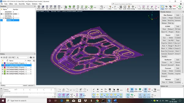
Above figure shows Mid Surface of Inner Extract.
After creating midsurface create separate PID for that midsurface and rename it as you want so that we can easily identify. Do this for all parts.
Steps invloved in Meshing
In Mesh option
STEP 1 : Give Element Size
Give the element size for the given model by goto Length>select perimeters of the model>in length give the element size as you want. Since the target length given for this model is 5mm i give the element size of 5mm for this model.
STEP 2 : Give Quality Criteria and Mesh Parameters
The shape of Elements in FE Analysis must be distorted from their Ideal shapes when meshing the irregular or complex geometric shapes. Every element is designed to work properly within a certain range of shape distortion. Exactly how much distortion and what type of distortion is allowed before an element degenerates depends on factors such as element type, numerical procedures used in the element design, and so forth. If the actual shape that the element assumes after mapping onto model geometry differs too much from the natural shape, the element becomes degenerated and produces erroneous results. The major types of degeneration are Aspect Ratio, Skewness, Jacobian Ratio, Warping Factor, Maximum Corner Angle, Orthogonal Quality, Parallel Deviation, Taper, Curvature distortion and mid-size node position. As per the given Quality criteria i give
S.No Quality Criteria Value
1 Target/Average length 5
2 Minimum Length 2
3 Maximum Length 7
4 Aspect ratio 3
5 Warpage 15
6 Skewness 45
7 Jacobian 0.7
8 Minimum Quad Angle 45
9 Maximum Quad Angle 135
10 Minimum Tria Angle 30
11 Maximum Tria Angle 120
10 Tria Percentage 15
Mesh Parameters
1 Target length 5
2 Minimum Target Length 2
3 Maximum Target Length 7
STEP 3 : Meshing
A mesh is a network that is formed of cells and points. It can have almost any shape in any size and is used to solve partial differential equations. Each cell of the mesh represents an individual solution of the equation which when combined for the whole network results in a solution for the entire mesh.
Before performing meshing we have to check for cons and nodes is passing my mesh parameters if not we have to perform defeaturing. Defeaturing means compromising with the one feature to save the another feature. Once the cons and nodes pass mesh parameters start meshing.
while performing mesh generation for shell(2D) component we have to reduce the number of trias as much as possible to get more accurate results and also avoid trias at free edges.
In case of complex geometry we should cut area into 2 or more sections to get good mesh flow. For ex :
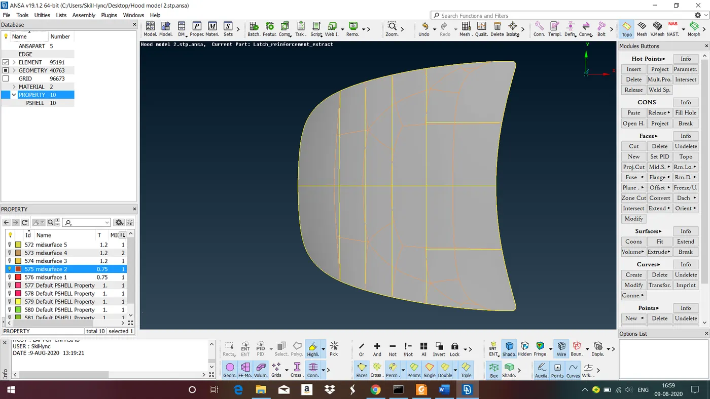
In the above shown complex geometry i cut one single geometry into 12 sections inorder to get good mesh flow.
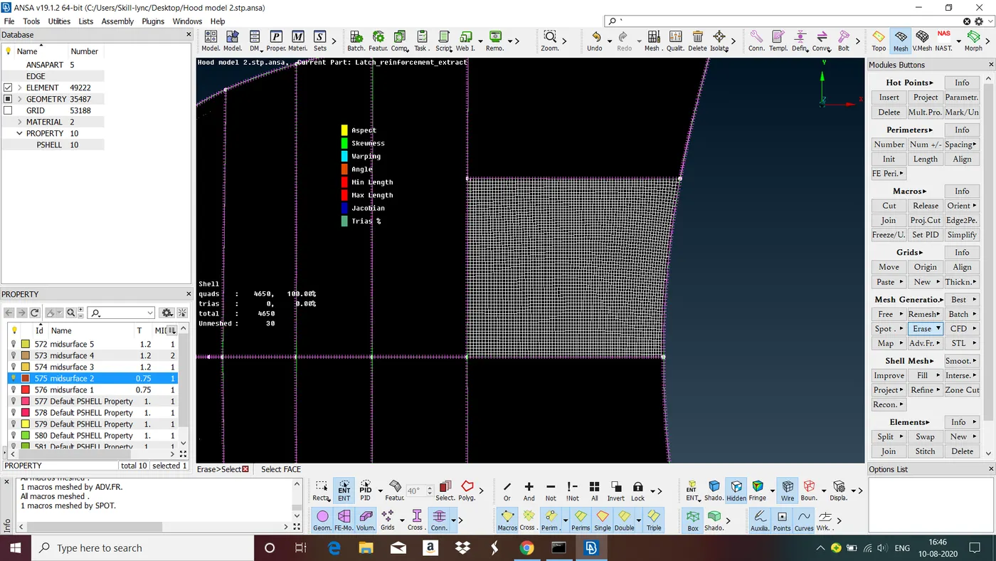
We use 'Best' in mesh generation option beacause it selects better mesh option for that particular area. If there are any mesh elements fail for the quality criteria, use 'Reconstruct' in shell mesh option. It will reconstruct the mesh and give best possible mesh with less number or no errors. Do this for all sections.
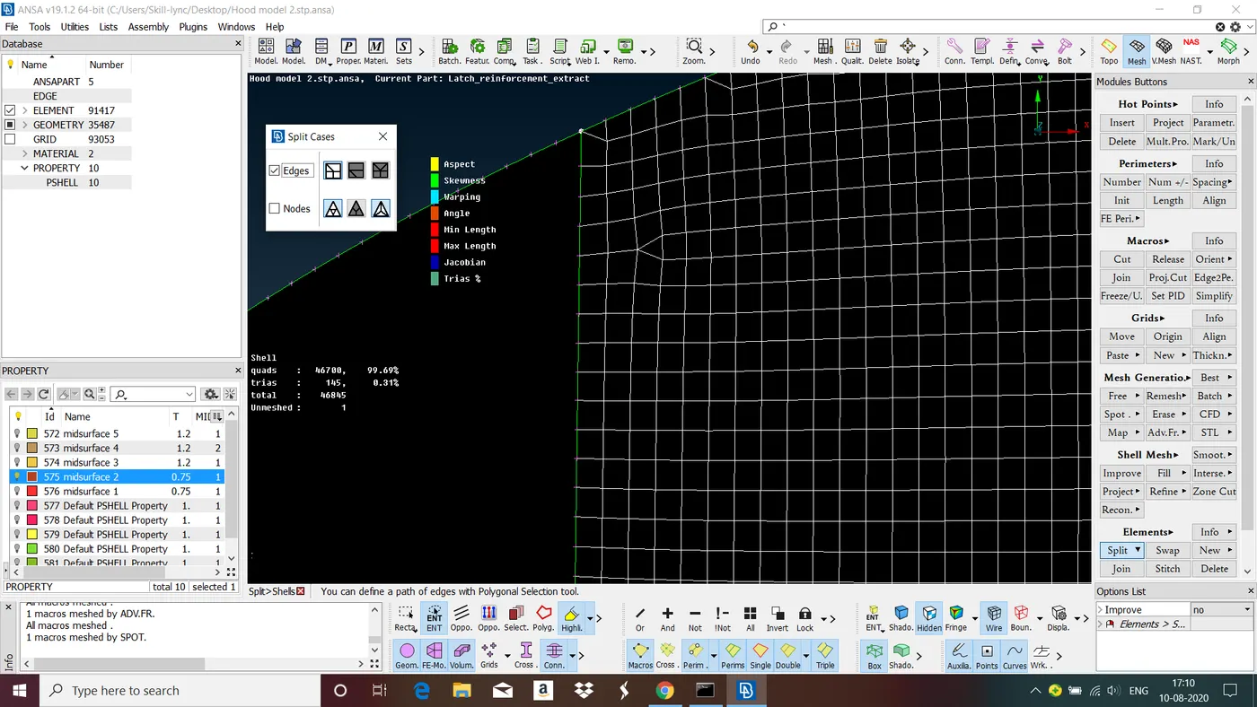
In the above figure there is a tria present in the mesh even though we performed reconstruct it is still there but it can removed manually by using 'Split' option. 'Split' option split the element into two.
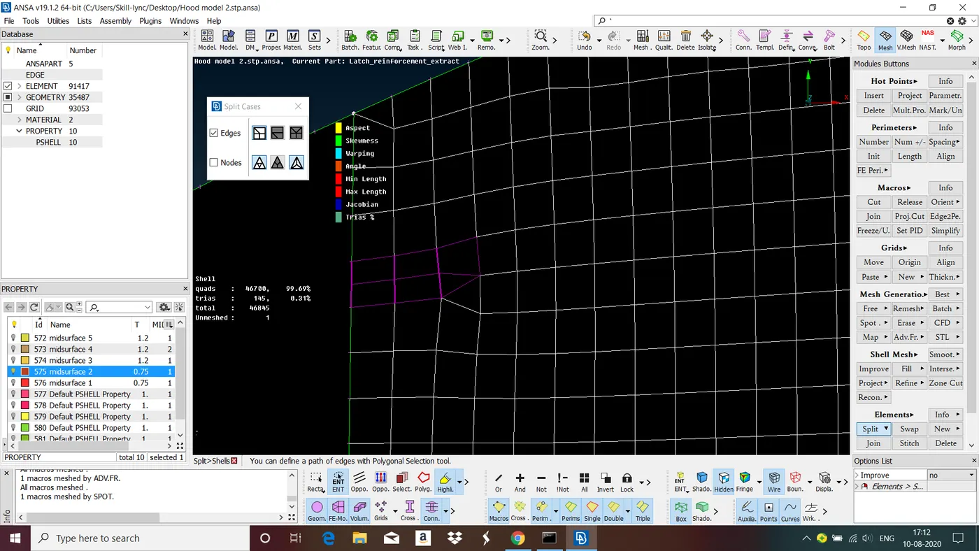
In the above figure i split the quad into one tria and one quad so that two opposite trias can be joined to make one quad.
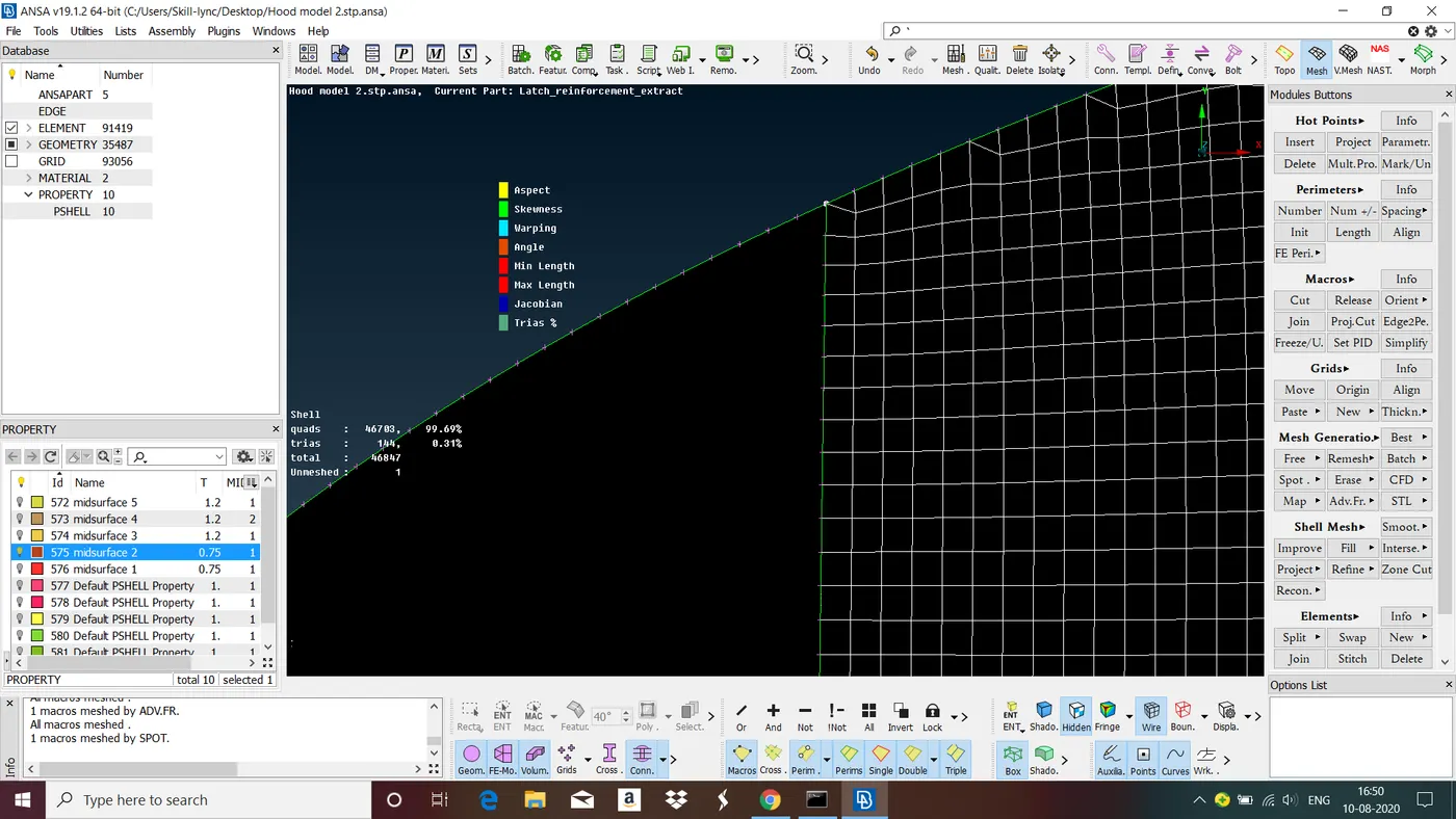
Above figure shows tria removed mesh by performing split method.
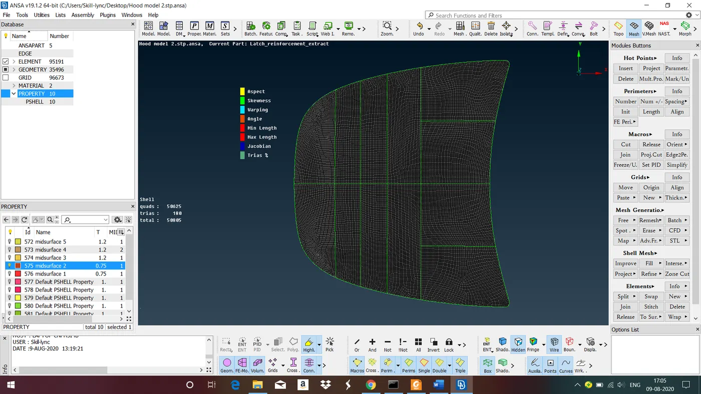
Above figure (Outer Extract) shows complete mesh generated model.
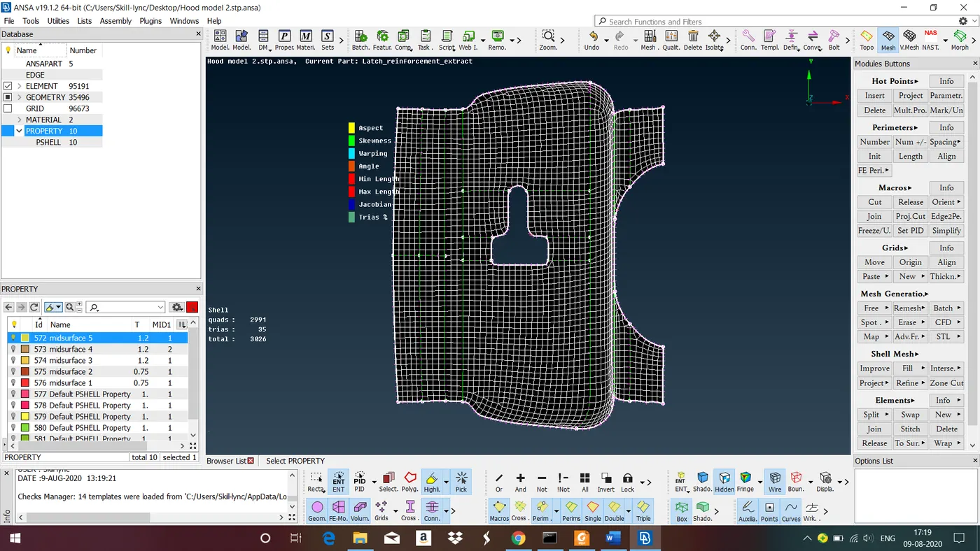
Follow these steps for all the parts to generate mesh.
Inner Extract :
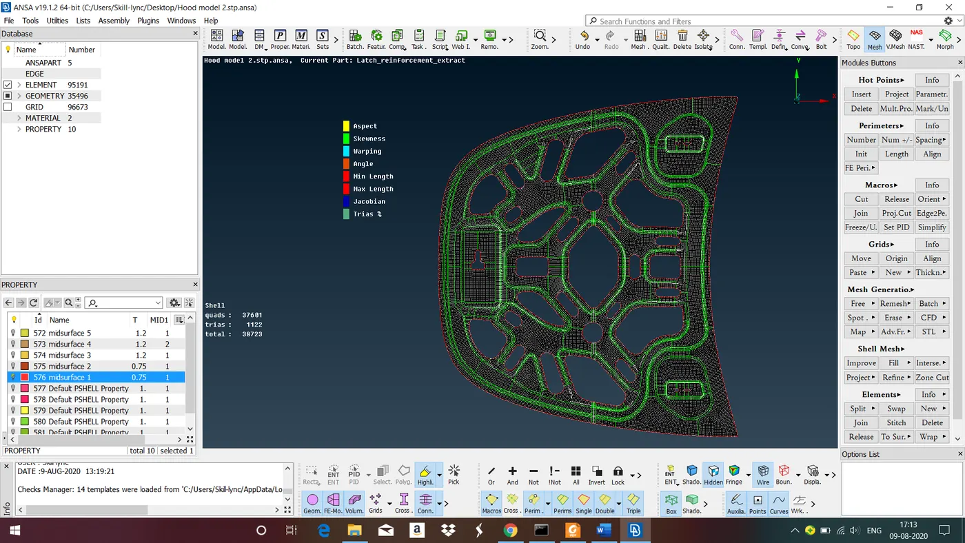
Hinges (left and Right) :
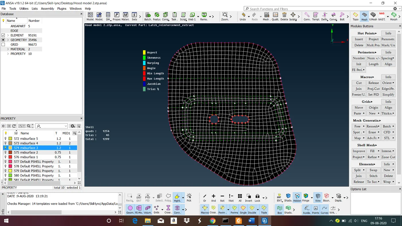
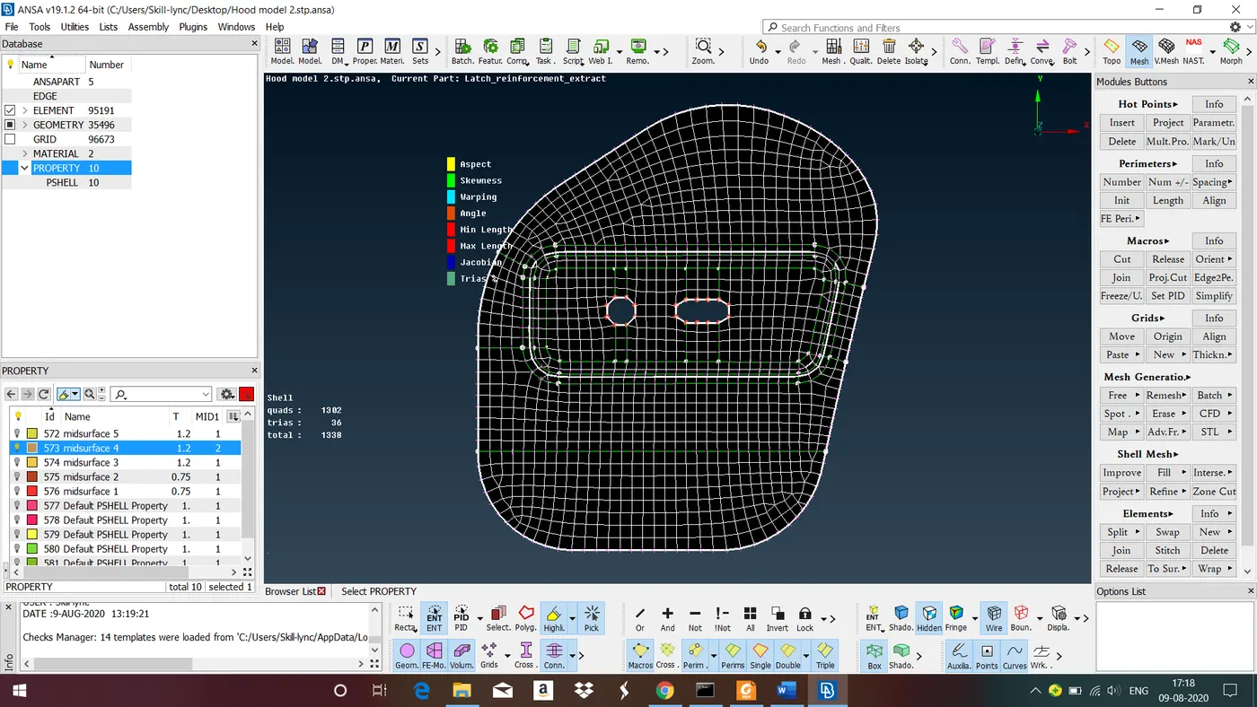
Latch :
Finished Model :
Isomteric view :
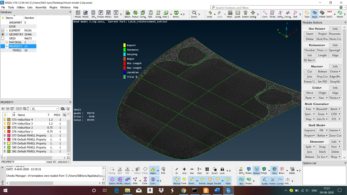
Bottom View :
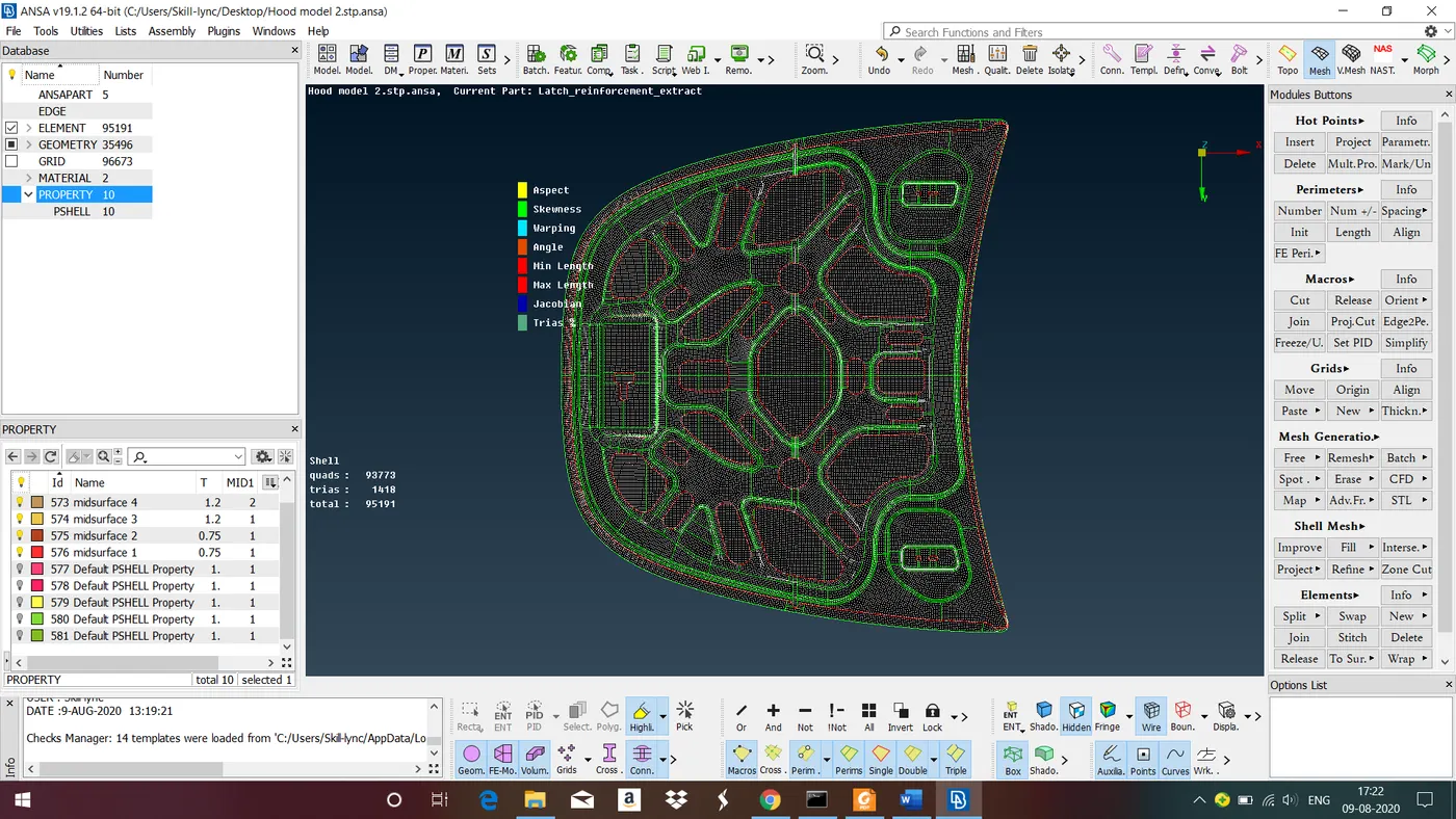
LEARNING OUTCOME :
In this challenge we have learned all the steps involoved in geometry cleanup, mid surface generation and meshing.
CONCLUSION :
In this challenge we have followed all the basic steps from geometry cleanup to meshing and obtained good mesh flow with zero error.