Side crash analysis of a Dodge neon BIW model as per FMVSS standards
AIM: To perform the side crash analysis of a Neon BIW model.
pre prcessing software:HyperMesh
Solving software:Radioss
Post processing software:HyperView and HyperGraph
Need for side crash analysis:
Some side impacts involve a vehicle travelling sideways into rigid roadside objects such as trees or poles. Often this is the result of a loss of control on the part of the driver, owing to speeding, misjudgement of a corner or because of a skid in slippery conditions. Such accidents are severe and the frequency of death or serious injury is high.
OBJECTIVE:
- Check unit system and either follow [Mg mm s] or [Kg mm ms].
- Create appropriate interface ,friction 0.2 and recommended parameters.
- Make sure of no penetration and intersections.
- Create rigid wall with friction 0.1 as per referance model.
- Compare the model weight with the referance model and use added masses to reach target weight 700kg while getting CG about the required range.
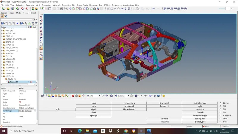
- Initial velocity as shown in picture.
- Use model checker to ensure good quality.
- Timestep :0.5 to 0.1 microseconds.
- Run 80ms.
Output requests:
- Sectional force in the cross member.
- Intrusion at B pillar,hinge pillar and fuel tank region.Provide recommendation on what can help to reduce Fuel tank intrusion.
- Peak velocity of inner node of the door.
PROCEDURE:
- Import the model
To import the model go to file>import>import solver deck>select the file>import.
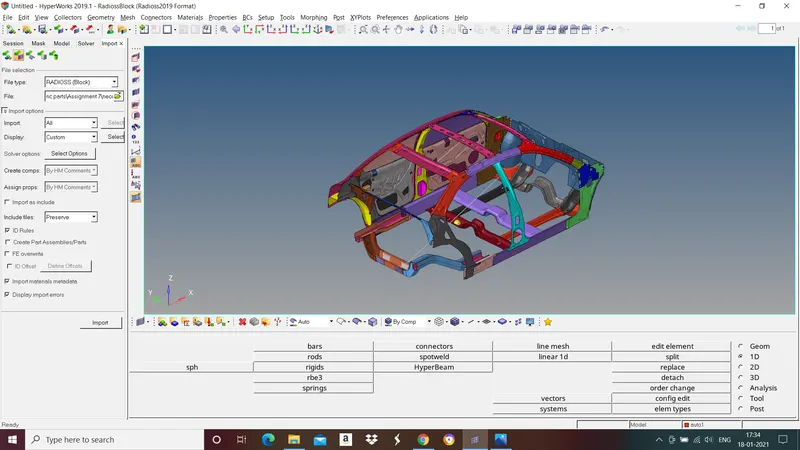
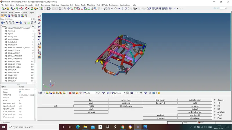
- Check unit system
To check unit system of imported model go to model browser in tab bar>cards>select begin card.
For this model it is in Kg,mm,ms.
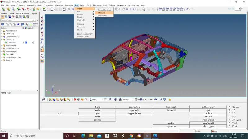
- Create appropriate interface
To create interface go to BCs in tool bar>create>interface.
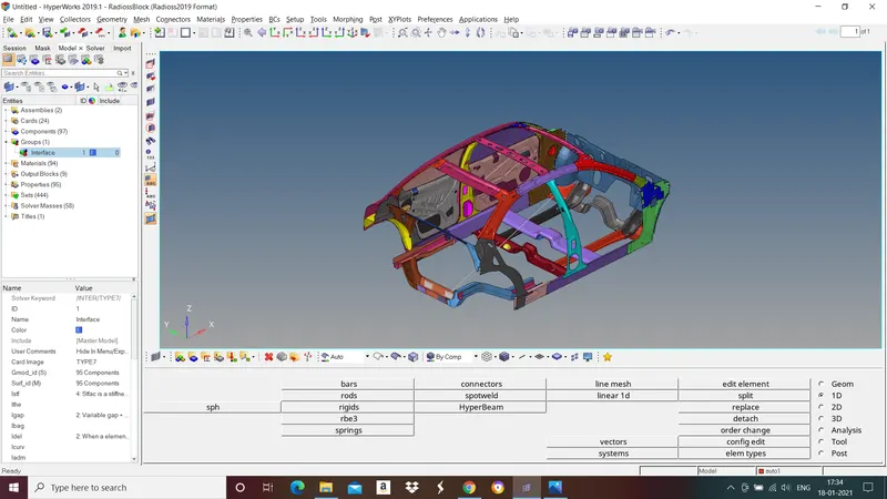
Change "Card image" to "Type 7". Select nodes(slave segment) in Grnod_id(s) and select surface(master segment) in surf_id(m).
Recommended parameters for Type 7 interface
- Istf = 4
- Igap = 2
- Idel = 2
- Stmin = 1
- Fric = 0.2
- Gapmin = 0.5
- Inacti = 6
- Iform = 2
- Create Rigid wall
To create rigid wall go to model browser in tab bar>create>rigid wall.
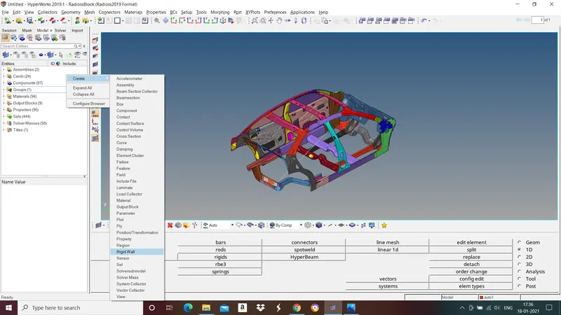
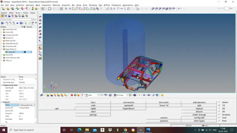
For side crash analysis we use cyclinder as rigid wall. To select rigid wall, in geometry type select cyclinder. Give XM,YM,ZM value to put rigid wall in desired location and normal value for direction.
Recommended parameters
Slide = 2(sliding with friction)
FRIC = 0.1
Dsearch = 1000
Diameter = 254.
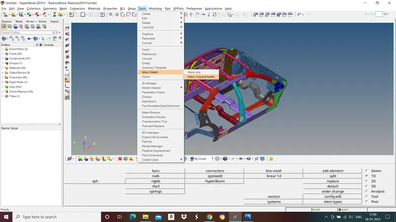
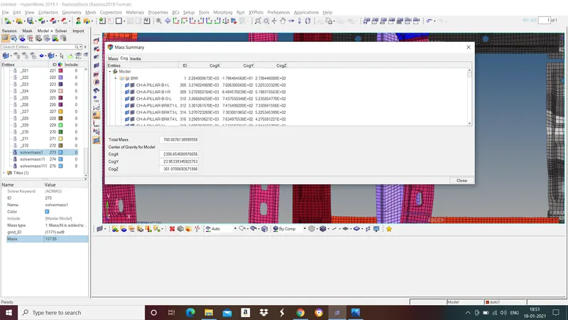
- Use added masses to reach target weight 700kg while getting COG about the required range.
To check present position of cog go to Tools>Mass details>mass, Cog and Inertia.
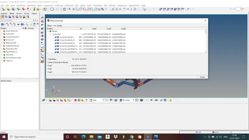
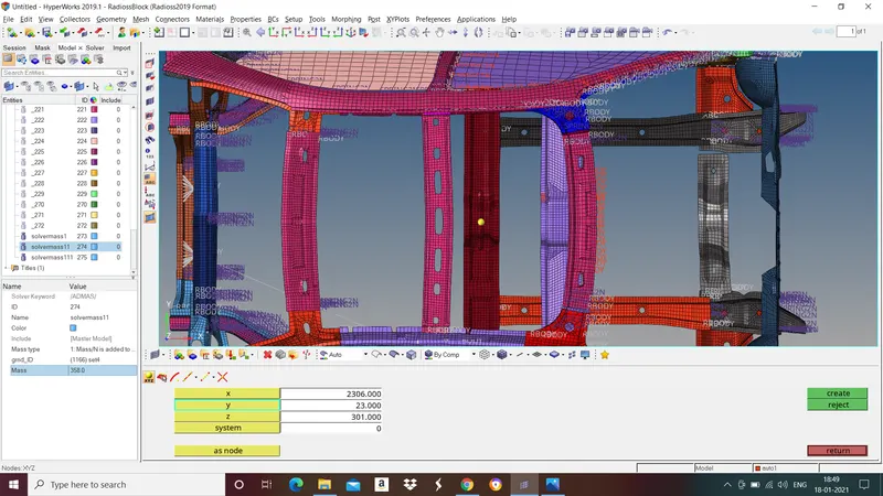
Note down Cogx,Cogy and Cogz value. Go to nodes>XYZ>give Cogx,Cogy and Cogz values in X,Y and Z respectively.
But COG of the given model should at the center. By adding masses we can get COG at required position. To add mass go to model browser in tab bar>right click select create>solver masses.
Select the nodes in "gnod_ID", mass type as 1 and give mass value.
Now we got cog at reqired position and also achieved target weight 700kg.
- Provide initial velocity to model.
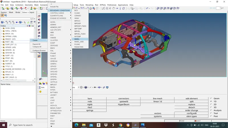
To apply initial velocity go to solver browser in tab bar>right click and select create>BOUNDARY CONDITIONS>INIVEL.
Give velocity value of 15.64 in Vy and select nodes in "Grnod_id".
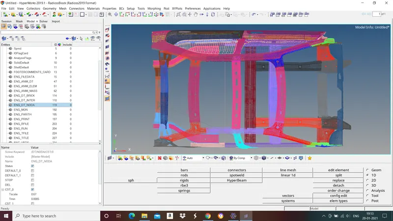
- Give Timestep value of 0.5 to 0.1 microseconds.
To give timestep go to model browser in tab bar>cards>ENG_DT_NODA>in Tmin give 0.0005.
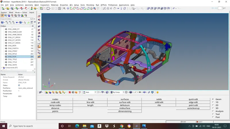
- Give Run time of 80ms.
To give run time go to model browser in tab bar>cards>ENG_RUN>in Tstop give 80.
Output requests:
- Sectional force in the cross member.
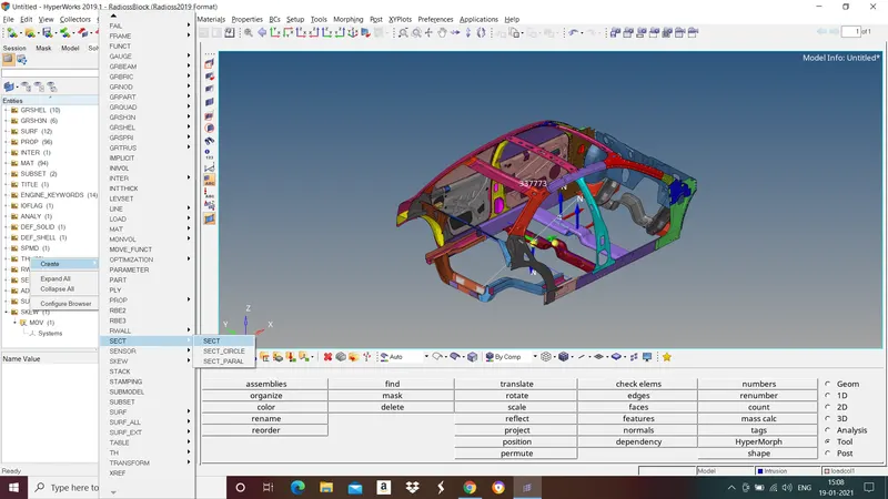
To create sections go to solver browser in tab bar>right click and select create>Sect>sect.
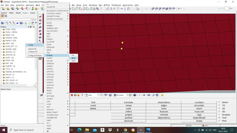
And also we need create local frame of reference to that section to do that go to solver browser in tab bar>right click and select create>Frame>Mov.
1st node - select the node where the frame must be located.
2nd node - Select the node in thr direction at which the z-axis must be located.
3rd node - Select the node based on origin where the YZ plane must be present.
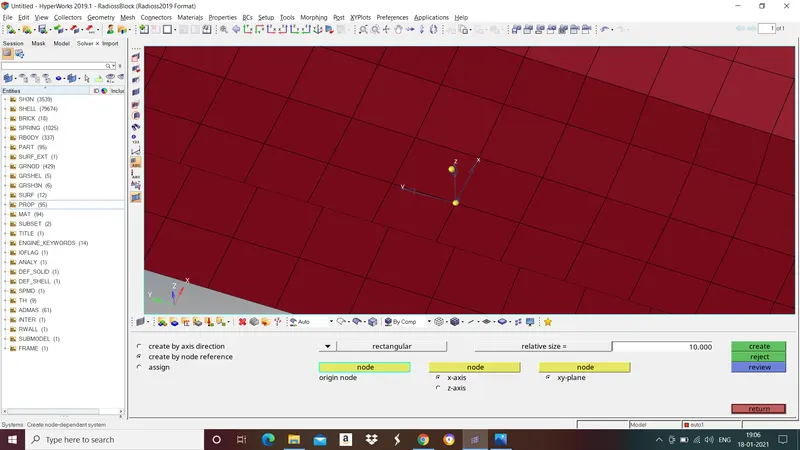
Now go to section menu in solver browser>select N1,N2 and N3, Frame_ID, select shell elements in Grshel_id, dt value of 0.1 and alpha 0.67.
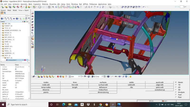
Follow the same procedure to create corss sections for all members.
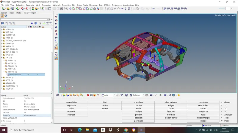
To create output block for cross sections go to solver browser in tab bar>right click and select create>TH>SECTIO>in Entity IDs select all the created cross sections.
- To check intrusions
Create spring element of small stiffness between node where we want to check intrusion and node of reference.
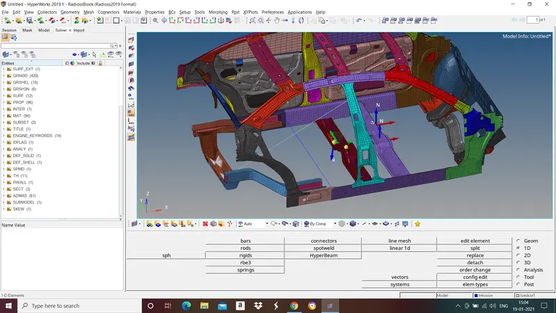
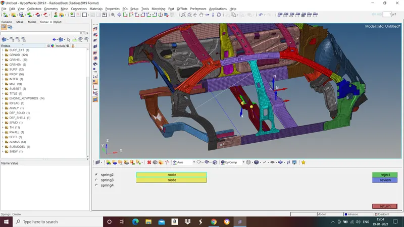
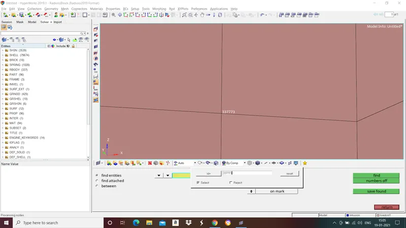
- To Check peak velocity at inner node(Node id = 337773) of door
To find that node go to tools>find>select "node" and right click select "by id">give node id.
We need to create skew to check peak velocity at the node to do it go to solver browser in tab bar>right click and select create>skew>mov.
1st node - select the node where the frame must be located.
2nd node - Select the node in thr direction at which the z-axis must be located.
3rd node - Select the node based on origin where the YZ plane must be present.
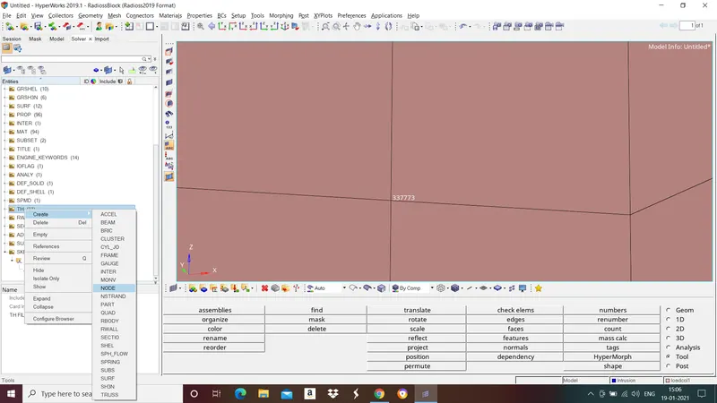
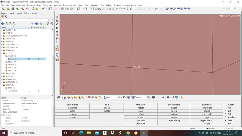
To create ouput block go to solver browser in tab bar>right click and select create>TH>Node>in Entity IDs select node and in Iskew select skew.
CHECK FOR ERRORS
Final procedure for any pre processing is checking for errors and fixing it. To check for errors in the model first export the model and open it in Hypercrash. In Hypercrash Go to quality>model checker>run.
Errors faced:
Empty files:
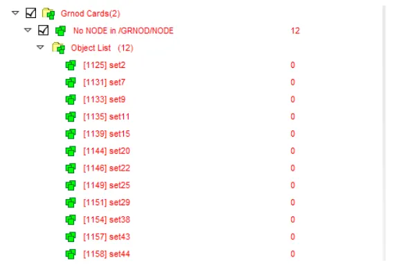
These empty shells were created while creating gr_nodes and gr_shells twice. Volume which is mentioned besides the file name shows "0" if the file is empty. Delete empty files.
SIMULATION RESULTS:
Animation result
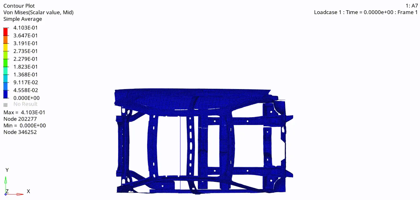
Fig: Side crash from top view (Vonmises stress)
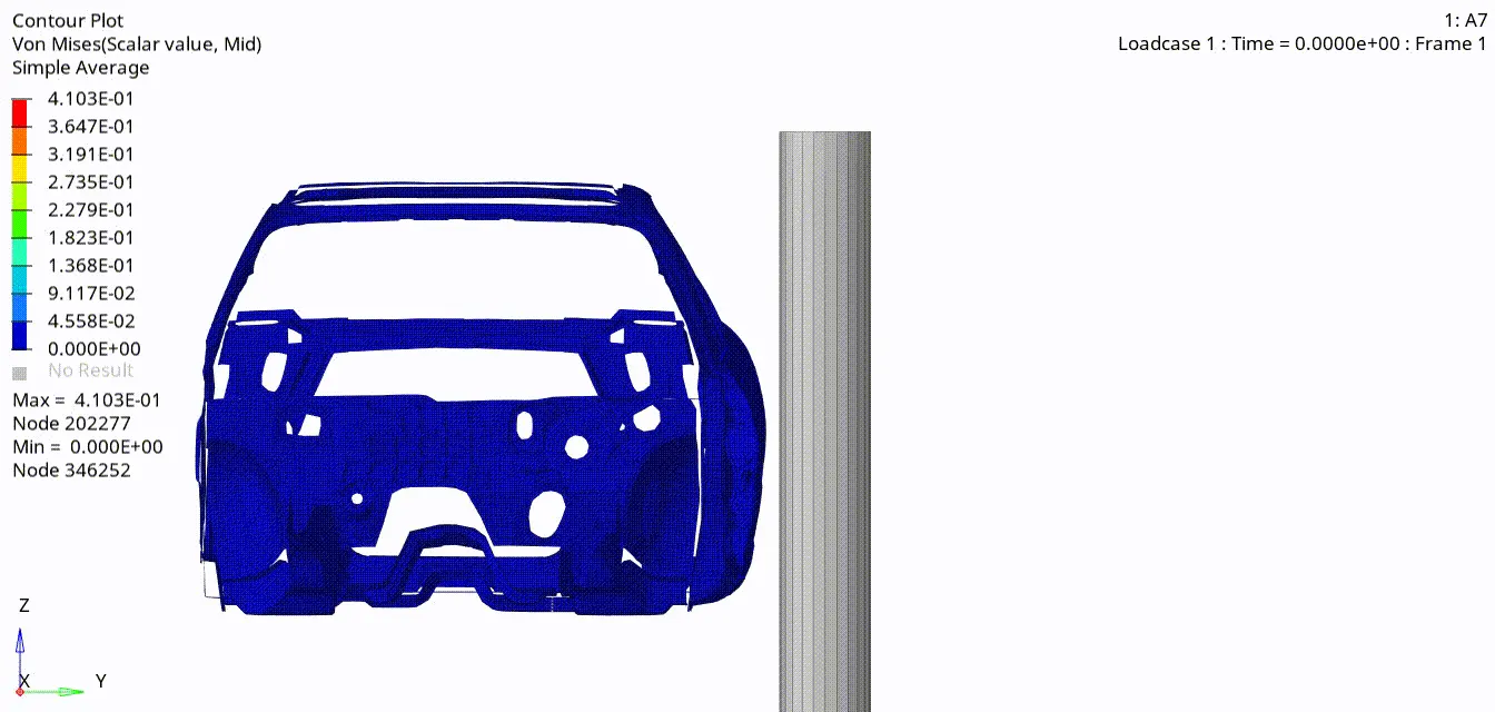
Fig:Side crash from front view (Vonmises stress)
- Total energy, Internal energy, Kinetic energy, Hourglass energy and Total energy
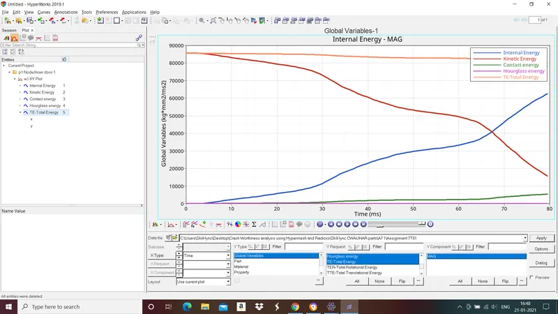
The kinetic energy that body has before the impact is transformed into internal energy, mostly by plastic deformationof the car body material(BIW). Total energy is the sum of kinetic energy and internal energy.
Since we have checked for penetrations and there were no penetrations found which helps in less contact energy developed in the body and it is less than 5% of total energy so our result is accurate.
There is very less hourglass energy is developed in the body because we have used fully integrated elements with recommended properties.
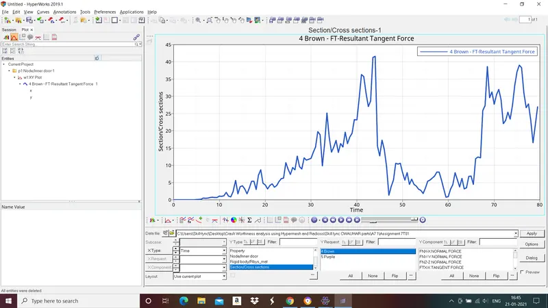
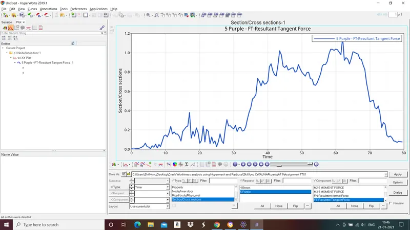
- Sectional force in the cross member.
A section is a cut in the structure, where forces, moments or energy will be computed and stored in output files (using /TH/SECTIO).
Cross memeber 1
Cross member 2
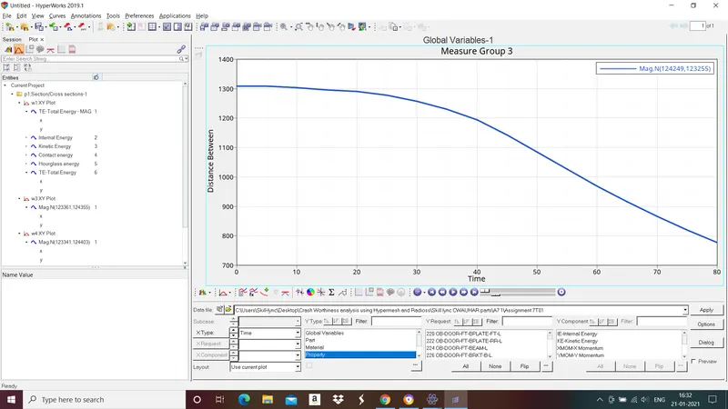
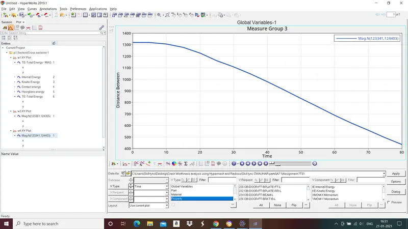
- Intrusion at B pillar,hinge pillar and fuel tank region.
Intrusion at Hinge pillar
Intrusion at B pillar
Intrusion at Fuel tank
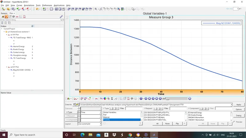
By adding adding cross member and increasing the material stiffness we can reduce intrusion at fuel tank region.
- Peak velocity of inner node of the door.
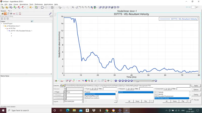
Peak velocity of the inner door is around 15.64 m/s after the crash velocity decreases.
CONCLUSION:
Energy error: 0 - 8.4%
Mass error: 0.4280E-04% - 0.6716E-04%
Intrusion at Hinge pillar:551.339 mm
Intrusion at B pillar:884.115 mm
Intrusion at Fuel tank region:629.278 mm
Simulation time:2:47 hrs
No. of cycles:160001