To mesh the given components with Tetra elements
AIM: To mesh the given components with Tetra elements.
METHODOLOGY:
- Import the model
- Topology repair
- Surface(2D) meshing
- Volume(3D) Meshing
- Quality check
PROCEDURE:
1.Import CAD model to Hypermesh:
Import geometry data via: Files > Import > Geometry(from drop down menu)
Common types of geometry files supported:
• Unigraphics (NX2, NX3, NX4, NX5)
• UG Part Browser
•Import of *.prt files
• Requires an installation of Unigraphics to be available
• CATIA (V4 & V5)
• import of *.model files
• CATIA V5 license required to import
• V5 files
• Pro/ENGINEER (Wildfire 2.0 & 3.0)
• import of *.prt and *.asm files
• IGES
• Import of *.igs / *.iges files
• STEP
• import of *.stp file
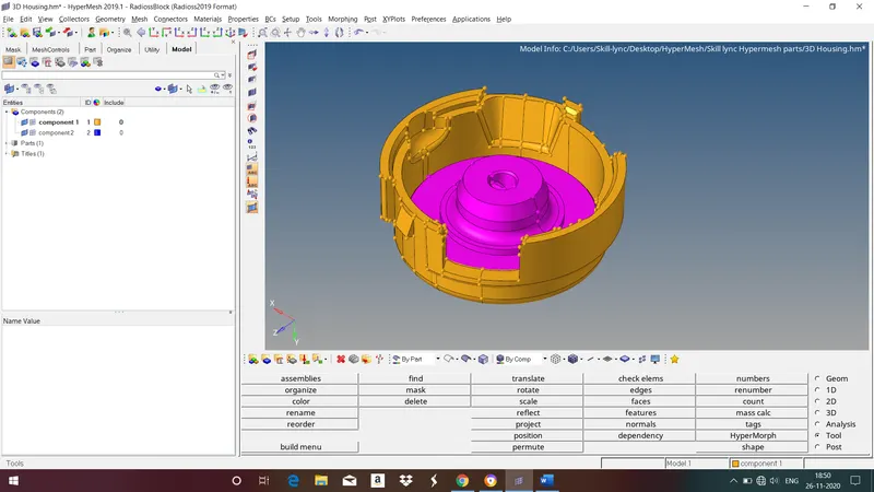
Model 1
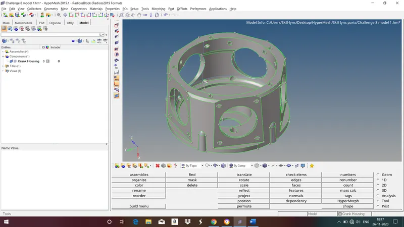
Model 2
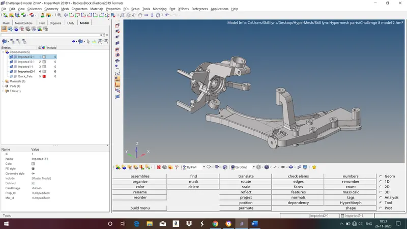
Model 3
• Surface connectivity is controlled by the associated surface edges.
• If a surface edge is associated with more than 1 surface, those surfaces are considered to be connected (“equivalenced”).
• Surface edges are categorized, named, and colored according to the number of associated surfaces:
Free edge (red):
• Associated with only 1 surface
• Surfaces with a free edge between them are NOT equivalenced at that edge
Shared edge (green):
• Associated with 2 surfaces
• Surfaces are equivalenced
T-junction edge (yellow):
• Associated with 3 or more surfaces.
• Example: surfaces forming a T-connection.
• Surfaces are equivalenced.
Suppressed edge (blue):
• Surfaces are treated as though combined into 1 surface.
2. Topology Repair:
HyperMesh will attempt to properly clean up surfaces during import
• Some types of geometry files have surface connectivity information which helps HyperMesh. Typically native geometry files like Catia, UG, ProE, etc.
Topology Repair consists of correcting connectivity errors between adjacent surfaces
Possible errors include:
• Unconnected adjacent surfaces
• Duplicate surfaces
• Missing surfaces
•Understand model size & scale to determine an appropriate global element size.
• Set a cleanup tolerance based on the determined global element size.
•Set appropriate value in options, geom cleanup, and automesh :cleanup.
•Cleanup tolerance specifies the largest gap size to be closed by topology functions.
• Tolerances > 15-20% of global element size can cause mesh distortions.
• Can change value multiple times for work on various areas of the model.
•Use topology display tools to decide what needs to be cleaned.
•Use equivalence to combine as many free edge pairs as possible.
• Make sure surfaces are not collapsed in undesirable manner.
•Use toggle to combine any remaining free edge pairs, 1 by 1
• use replace function if more control is needed.
•Use find duplicates to check for any duplicate surfaces and delete them.
•Use filler surface to recreate any missing surfaces.
The Goal of Topology Repair: Restore the surface data to a perfectly clean representation of the part.
3. Surface (2D) meshing:
A mesh is network that is formed of cells and points. It can have almost any shape in any size and is used to solve partial differential equations. Each cell of the mesh represents an individual solution of the equation which, when combined for the whole network, results in a solution for the entire mesh.
Before proceeding to meshing give element length and quality criteria. To do this go to Preferences in title menu bar>criteria file settings>give quality criteria>apply>close.
Quality criteria for model 1
| Sl no. | Quality Criteria | Value |
| 1 | Target Length | 5 |
| 2 | Min Length | 2 |
| 3 | Max Length | 7 |
| 4 | Tet Collapse | 0.15 |
Quality criteria for model 2 and model 3
| Sl no. | Quality Criteria | Value |
| 1 | Target Length | 6 |
| 2 | Tet Collapse | 0.15 |
For tetra meshing first we should mesh the surfaces with tria elements.
Now start meshing surface by surface to get better mesh flow. To do this go to 2d>automesh>select the surface>select the element type>mesh.
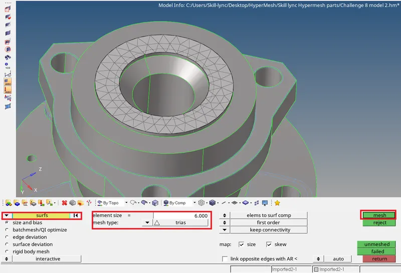
Fig : Meshing Surfaces with 2D elements.
Follow the same steps for all the Components.
4. Volume(3D) Meshing:
Tetrahedral is a four nodded solid element which can be generated through the tria element by creating a volume and also through the existing volume of the geometry. These elements are used where the geometry has high thickness and complexity. Tetra element will have 4 triangular faces with four nodes joining them together.
Methods to generate Tetra meshing
- Conversion of 2D tria to tetrahedral elements, by using Tetra mesh panel.
- Using the quick tetra mesh, from the utility panel.
- Using the volume tetra mesh panel.
1. Conversion of 2D tria to tetrahedral elements, by using Tetra mesh panel.
steps to followed
1. Import the model into Hypermesh and clean the geometry
2. Delete the solid from the model, by selecting Delete>solid>delete solid.
3. Now perform the 2D meshing on the model, by selecting the mesh type as trias.
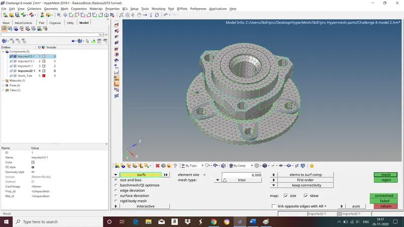
Fig: Surfaces are meshed with 2D elements.
4. After completing the 2D meshing the model should be cleared with minimum and maximum elemental error.
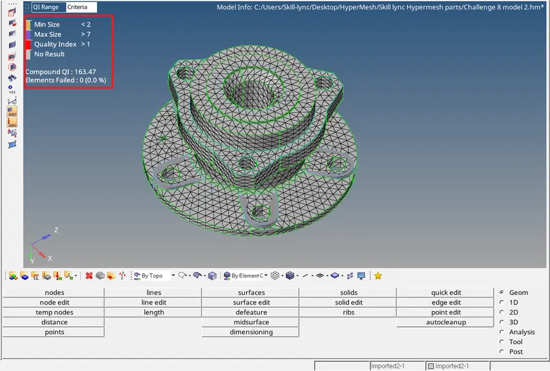
Fig : Showing zero elements failing for quality criteria.
5. Now the model is ready to perform the tetra meshing. select 3D>tetramesh>Select the elements under the Fixed trias/quads to tetra mesh option>select the elements>mesh.
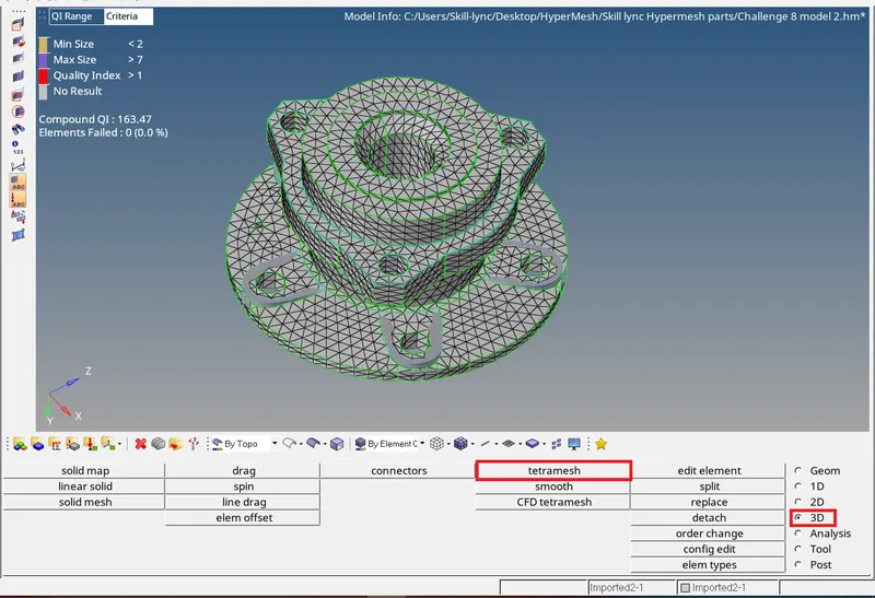
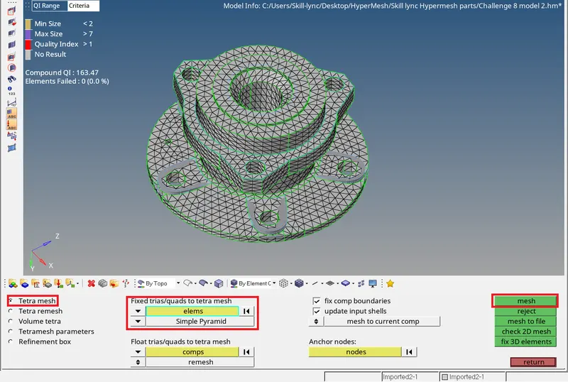
Fig : Tetra Meshing
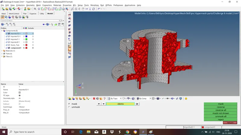
6. Once the tetra meshing was completed, mask a few elemetns to check the mesh generation.
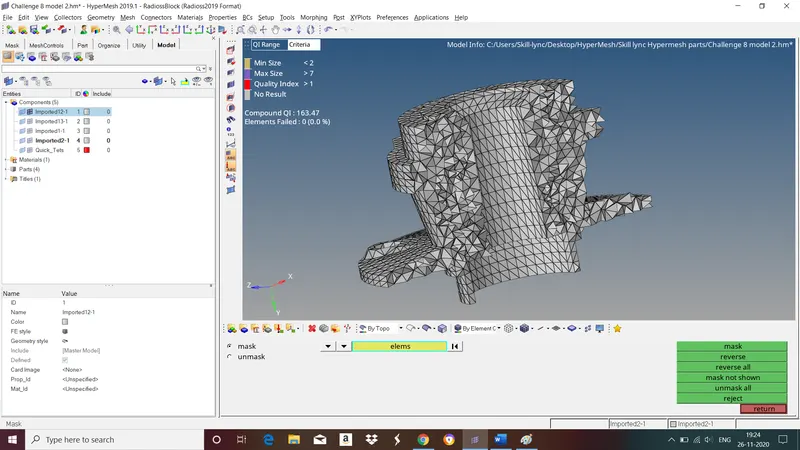
Fig : Tetra elements
2. Using the quick tetra mesh, from the utility panel.
steps to be followed
1. Import the model into Hypermesh and clean the geometry.
2.Delete the solid from the model by selecting the Delete>solid>Delete entity.
3. Click on the View>Browsers>Hypermesh>utility>Geom/Mesh>Quick tetramesh.
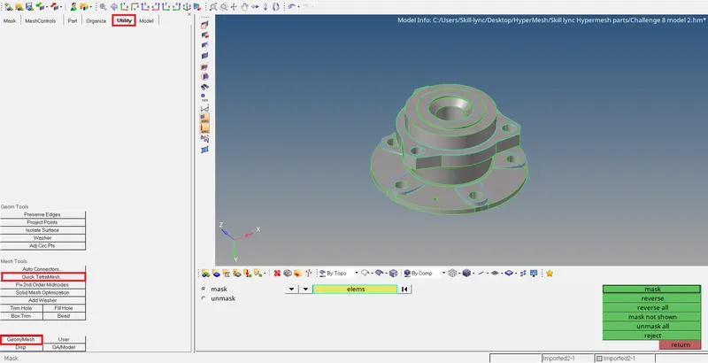
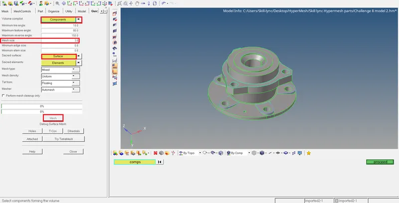
4. In Quick tetramesh Tab select the components and surfaces and give mesh size and mesh type. Click on the mesh button to generate the tetra mesh.
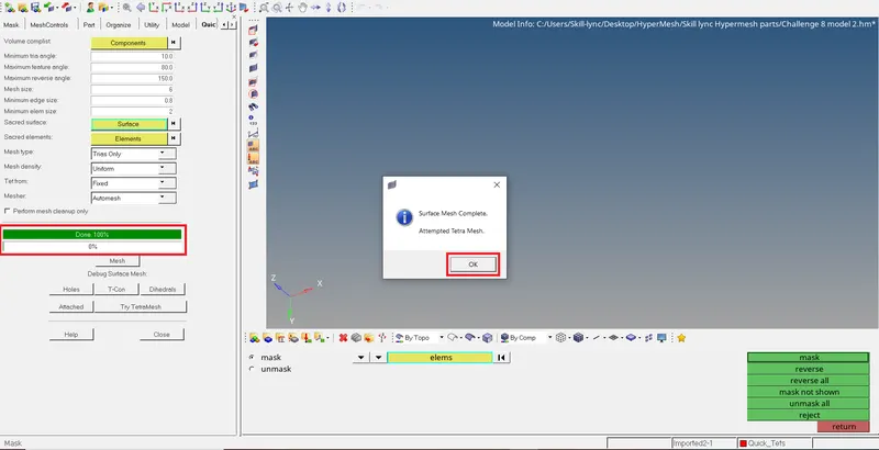
5. Click on the OK button to complete the tetra meshing process. Meanwhile a new component collecter will be created in the tab bar which contains the tetrahedral elements.
3. Using the volume tetra mesh panel.
Steps to be followed
- Import the model into Hypermesh and clean the geomtery.
- Keep the solid of the model, select 3D>tetramesh>volume mesh.
- In volume mesh panel select the solids, tick the checkboxes of 'use curvature', 'cleanup elements', 'use proximity', Specify the minimum element size and click on mesh.
I used 1st method to tetra mesh the given components.
5. Quality Check:
1. For 2D elements we check for minimum and maximum length.
2. For 3D elements we check for Tet Collapse
Tet collapse is one of the quality parameters, which will be checked while generating Tetrahedral elements. It can be calculated by measuring the distance of a node from the opposite face, then of the four values will be divided by the square root of the opposte faces area. The minimum of four resulting values is then normalized by dividing it by 1.24.
Generally tet collapse can be calculated by the formula = Min of (h/`squareroot`A)`divide`1.24.
h=Height between the node N1 and the opposite face of the triangle.
A=Area of opposite face of triangle.
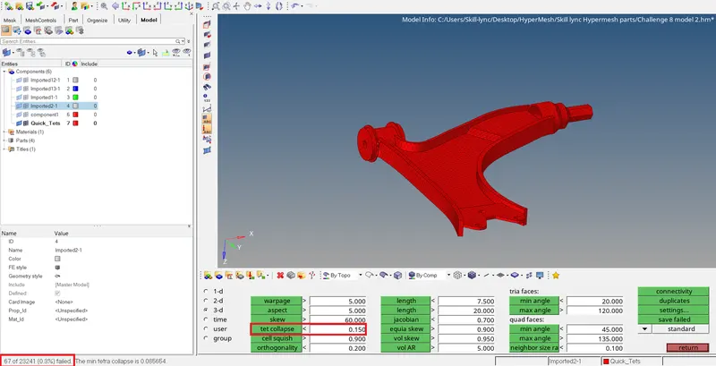
In the figure we can see there are 67 out of 23241 elements failing for Tet collapse.
Methods to clear tet collapse
1. Using the translate command to increase the height.
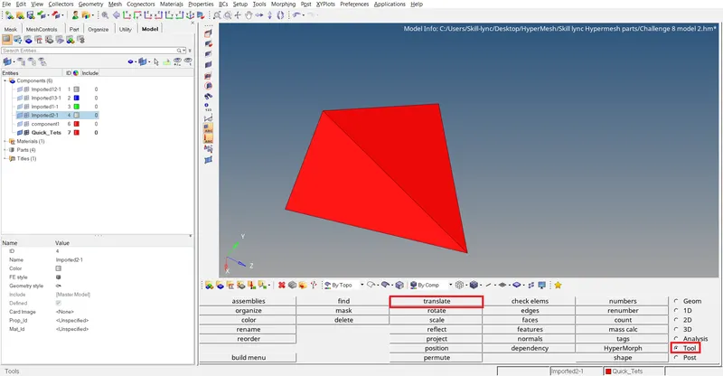
Goto tool>translate.

- Pick a node in any one failed element which has minimum height.
- Select N1,N2 and N3 which represents opposite plane of the prior selected node.
- Select magnitude value approximately by trial and error method.
- Click on the translate button to translate the node.
- After correcting failed element parallely check tet collapse value in the 'check elems' option.
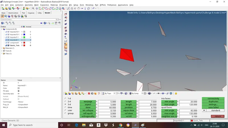
Now the element is passing for tet collapse. Follow the same steps to clear remaining elements.
2. Using tetra remesh panel to remesh failed elements.
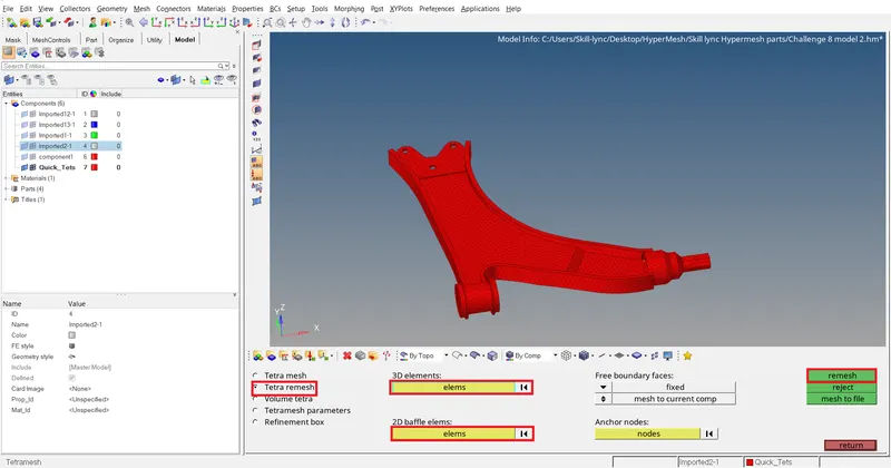
Goto 3D>Tetra remesh>select 2D elements and 3D elements>remesh.
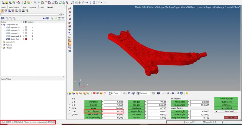
After remeshing we can see all the tetra elements passing for tet collapse.
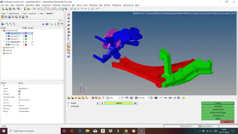
Final model :
Model 1
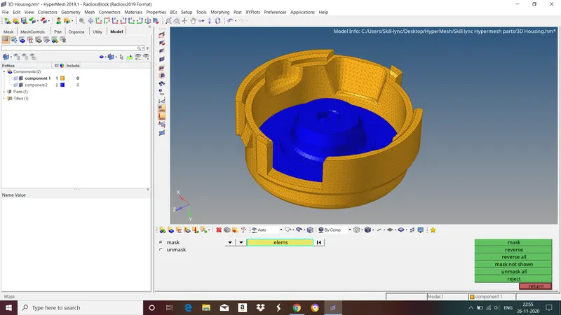
Model 2
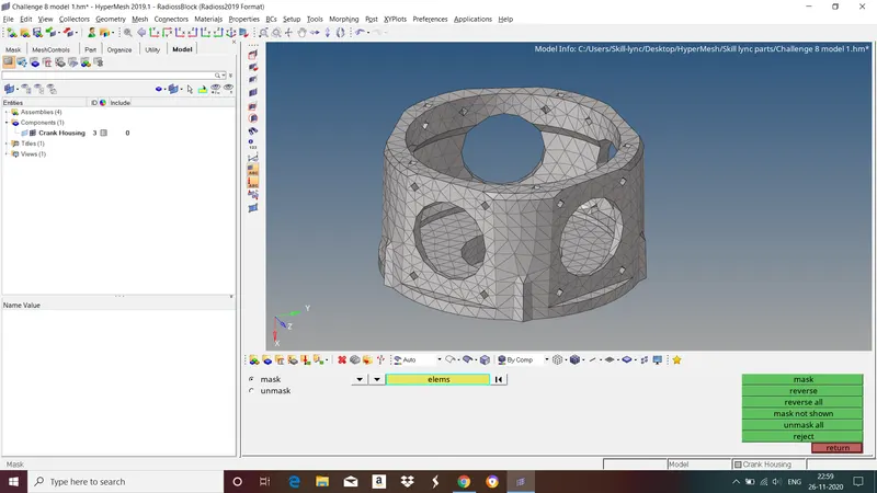
Model 3
LEARNING OUTCOME :
- Surface meshing using tria elements.
- 3D meshing with using Tetra elements.
CONCLUSION : In Challenge we have followed all steps involved in 3D meshing and obtained good mesh flow with zero elements failing for quality criteria.