Assignment 3
AIM: To run the analysis in radioss for given FE Mesh and compare the results with base simulation and improved shell element properties.
OBJECTIVES:
1.Using the crash beam file from the previous assignment, change the run time to 55 ms.
- Import given 0000.rad file to hyperworks.
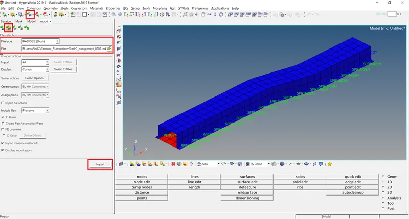
Goto 'Cards' in in tab menu>ENG_RUN>Change 'Tstop' 55.
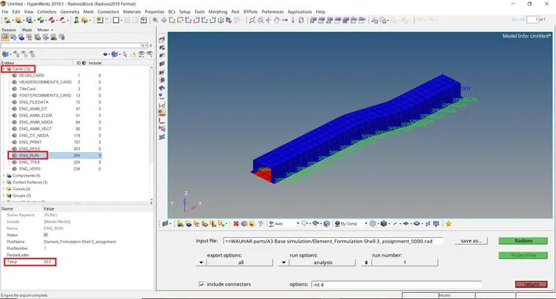
2. Change the number of animation steps during simulation to a minimum of 25 and maximum of 60.
I assume 40 animation steps
for 40 animation steps Tfreq=Runtime/No. of animation steps.
Tfreq=1.375.
Go to 'Cards' in tab menu>ENG_ANIM_DT>change 'Tfreq' to 1.375.
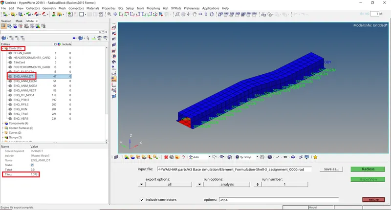
3. Run the base simulation without any modification to element properties.
To run the simulation
- Go to analysis>save the file>select all the necessary parameters>Radioss.
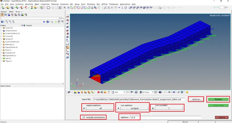
4. At the end of the simulation, do the energy error and mass error checks and determine whether results would be acceptable.
To check Energy error open 0001.out file in notepad.
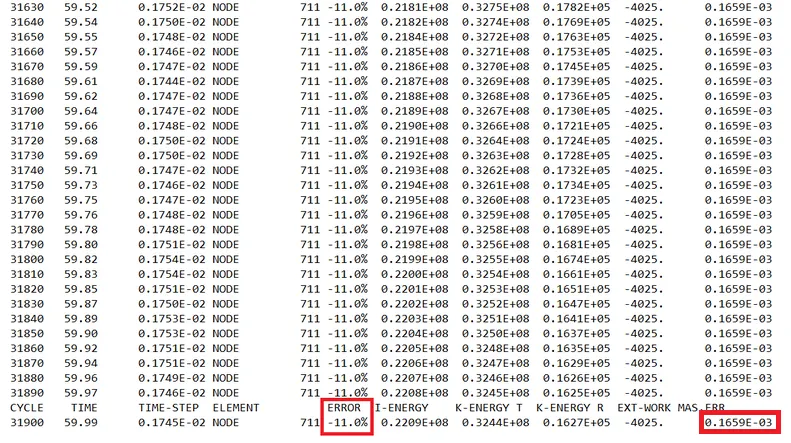
Fig: Energy error and mass error in the base simulation
The error must be negative and decreasing (except for the first cycles or in spring back stage). The error must be less than 15% at the end of the computation (5% for a good model). If the error increases a little, then decreases may be normal. If the error increases, this means that a problem has occured. Then, the error may grow to 99.9% with computation failure message. So ideally the error should be at most -15%c and better to have -5%. The closer to 0% error the better. Mass error should be less than 2%.
5. If acceptable, Plot rigid wall forces, internal energy, hourglass energy, contact energy, total energy of the simulations
Since the Energy error in the above simulation result is less than -15% lets plot "rigid wall forces", "internal energy", "hourglass energy", "contact energy", "total energy" graphs.
For internal energy, hourglass energy, contact energy, total energy graph:
Goto Hypergraph profile>select open file option>select T01 file>in Y type select global variable, in Y request select internal energy, hourglass energy, contact energy, total energy and in Y component select MAG>apply.
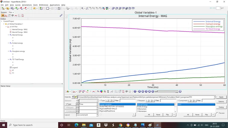
Fig: internal energy, hourglass energy, contact energy, total energy Curves.
For Rigid wall forces:
In Y type select "Rigid wall/Rwall-force", in Y request select "4 Rigid wall 1" and in Y component select "Resultant Normal force", "Resultant Tangent force" and "Total resultant force".
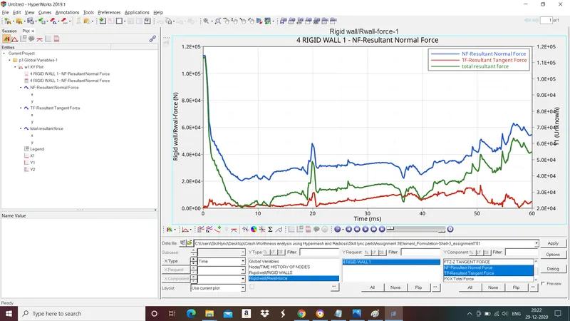
Fig: Rigid wall forces curves.
6. Change all the shell elements properties to recommended properties, save this as separate, rad files and run the simulation.
Recommended properties
|
Ishell =24 |
QEPH 4 nodes shells are best combination of cost and accuracy. |
|
Ismstr=2 |
Full geometric nonlinearities (default)with possible small strain formulation activation in RADIOSS Engine. |
|
Ish3n=2 |
Standard 3 noded shell (C0)with modification for large rotation(default) |
| N=5 | Number of integration points set to 5 for accuracy bending. |
|
Ithick=1 |
Thickness change is taken into account for accuracy. |
|
Iplas=1 |
Iterative plasticity for good accuracy. |
- Import given 0000.rad file to hyperworks.
- Change the shell element properties to recommended properties.
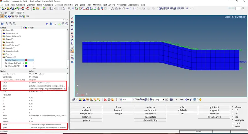
- Now run the analysis by Go to analysis>save the file>select all the necessary parameters>Radioss.
7. At the end of the simulation, do the energy error and mass error checks and determine whether results would be acceptable. If acceptable, Plot rigid wall forces, internal energy, hourglass energy, contact energy, total energy of the simulations.
To check Energy error open 0001.out file in notepad.
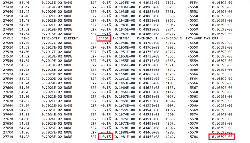
Fig: Energy error and mass error in the base simulation
Like explained above the energy error must be less than -15% mass error less than 2% at the end of the computation. Lets plot rigid wall forces, internal energy, hourglass energy, contact energy, total energy of the simulations.
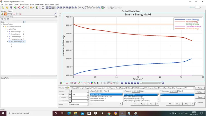
Fig: internal energy, hourglass energy, contact energy, total energy Curves.
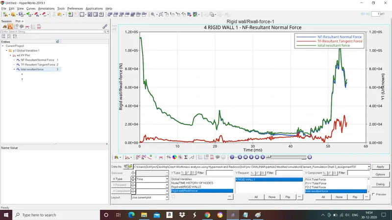
Fig: Rigid wall forces curves.
8. Create a brief report comparing all the results for both simulations
From Base simulation we can say
- Internal energy is strain energy that is stored in a body during deformation. It is zero at t=0 sec and increases due to deformation and approximated to 1.93E+07 at the end of 55ms.
- Kinetic energy starts from high value because we have initial velocity and huge mass and decreases due to deformation and approximated to 3.56E+07 at the end of 55ms.
- There is no changes in contact energy.
- Total enegry is the sum of Kinetic energy, potential energy and internal energy and it should be flat line since hourglass energy is present it effects the total energy curve.
From Modified simulation we can say
- Internal energy is strain energy that is stored in a body during deformation. It is zero at t=0 sec and increases due to deformation and approximated to 1.97E+07 at the end of 55ms.
- Kinetic energy starts from high value because we have initial velocity and huge mass and decreases due to deformation and approximated to 4.15E+07 at the end of 55ms.
- There is no changes in contact energy.
- Total enegry is the sum of Kinetic energy, potential energy and internal energy and it should be flat line. since hourglass energy is zero throughout simulation total energy curve remains unchanged.
Deformation comparision
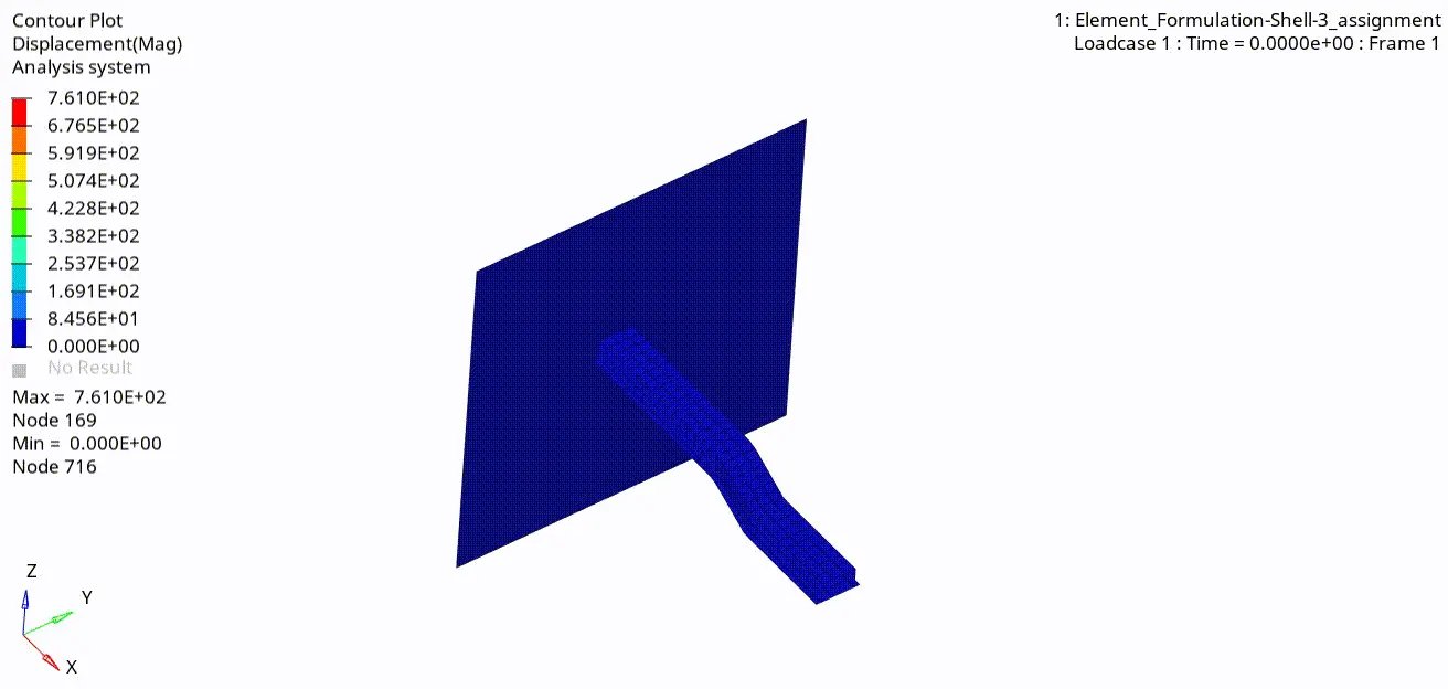
Fig: Base Simulation
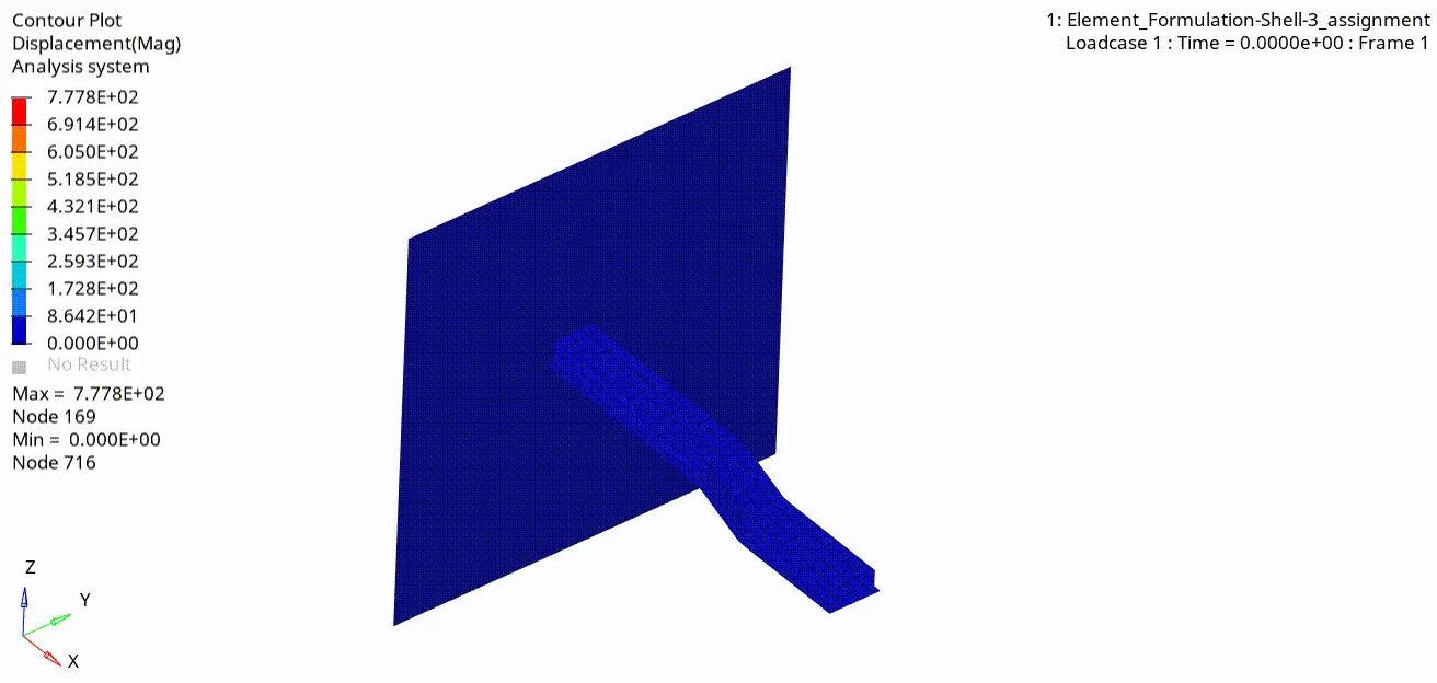
Fig:Modified Simulation
9. Comment whether there is any change in the results and why there is any change in the result.
After changing recommended properties for shell elements we got more acceptable result than base simulation results. This is because of using
- QEPH 4 noded reduced integration shell instead of Q4 shell.
- Ismstr=2 Full geometric nonlinearities with possible small strain formulation activation in RADIOSS Engine.
- Ithick=1 Thickness change is taken into account for accuracy.
- Iplas=1 Iterative plasticity for good accuracy.
Hourglass Effect
Hourglass modes are nonphysical modes of deformation that occur in underintegrated elements(Elements with single integration point) and produce no stress.
Why it appears
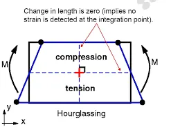
When the element subjected to loading change in length is indication for axial strain and in angle shear strain. But when it is subjected to bending loading at integartion point neither length nor angle changes. This bending mode of deformation is thus a zero energy mode because no strain energy but still element distortion exists.
How to avoid it
By using reduced integration elements Ishell=1,2,3,4 and Ishell=24.
Ishell=1,2,3,4(Q4) employs perturbation method for controlling hourglassing.
Ishell=24 employs physical stabilization method for controlling hourglassing.