To geometry cleanup, extract midsurface and meshing the given components
AIM: To geometry cleanup, extract midsurface and meshing the given components.
PROCEDURE:
For 1st Component
1. Import the model
Import geometry data via: Files > Import > Geometry drop down menu.
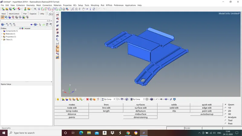
Fig: Given Component
2. Geometry Cleanup
HyperMesh will attempt to properly clean up surfaces during import.
Topology Repair consists of correcting connectivity errors between adjacent surfaces
Possible errors include:
• Unconnected adjacent surfaces
• Duplicate surfaces
• Missing surfaces'
The Goal of Topology Repair: Restore the surface data to a perfectly clean representation of the part.
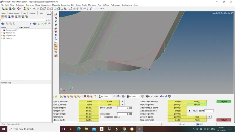
Fig: Free edges
Use toggle to combine any remaining free edge pairs, 1 by 1.
use replace function if more control is needed.
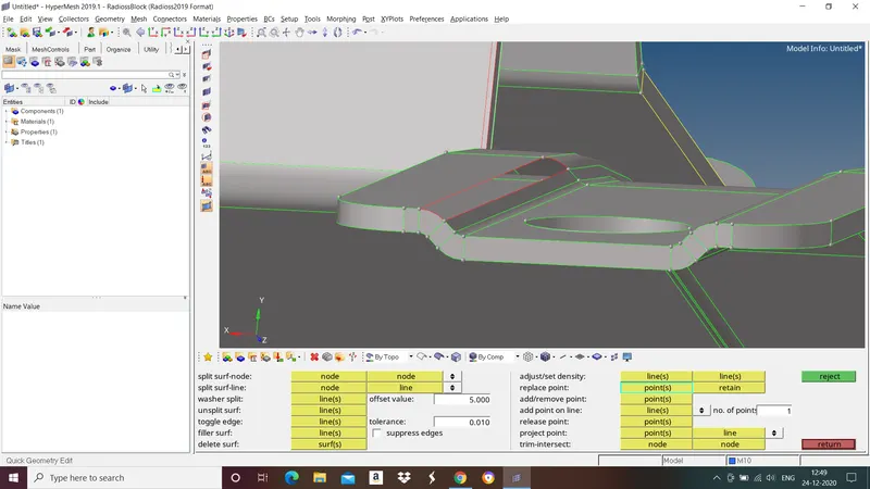
Fig: Missing surfaces
Use filler surface to recreate any missing surfaces.
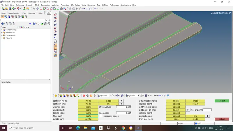
Fig: Duplicate surfaces
Use find duplicates to check for any duplicate surfaces and delete them.
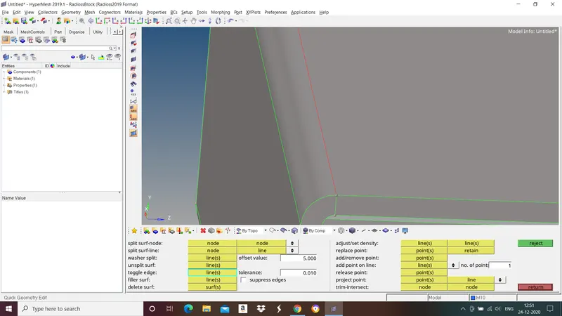
Fig: Free edges
Use equivalence to combine as many free edge pairs as possible.
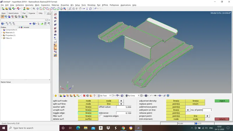
Fig: Geometry after geometry cleanup.
3.Extract Midsurface
Components which are having thickness less than or equal to 5mm we take midsurface for those components and mesh it with shell elements.
The child component extracted should be an exact replica of parent component.
Go to Geom>midsurface>select auto midsurface and from drop down menu and select closed solid>select the surfaces>extract.
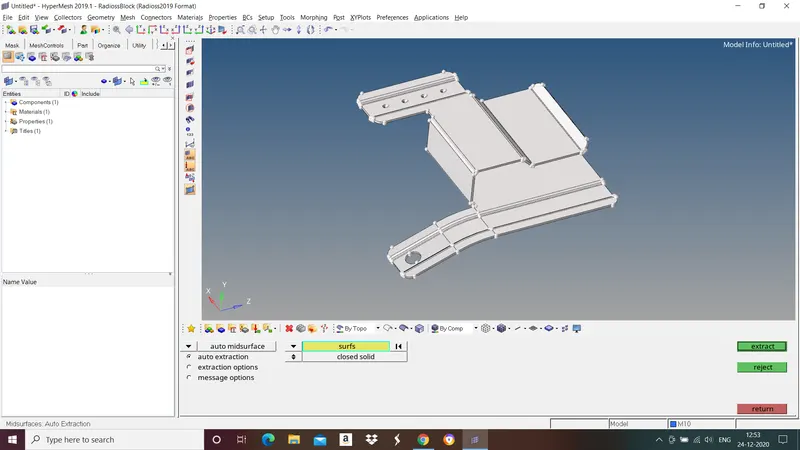
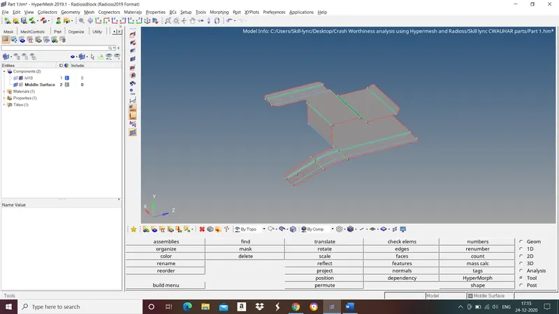
Fig: Midsurface
4.Assign thickness
After extracting mid surface we have to assign property, material and thickness for that mid surface.
To assign material go to tab bar right click>create>material>select newly created material and right click>edit>give material and its properties>close.
To assign property go to tab bar right click>create>property>select newly created property and right click>edit>give thickness and material>close.
Now goto tab bar, in components select mid surface component right click>edit>assign created property>close.
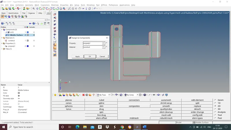
Fig: Assigning Material and property
5.Meshing
A mesh is network that is formed of cells and points. It can have almost any shape in any size and is used to solve partial differential equations. Each cell of the mesh represents an individual solution of the equation which, when combined for the whole network, results in a solution for the entire mesh.
Before proceeding to meshing give element length and quality criteria.
To do this go to Preferences in title menu bar>criteria file settings>give quality criteria>apply>close.
Target Length - 5mm
Min length - 3.5mm
Max length - 7mm
Give washer splits for holes to get good mesh flow.
Now start meshing surface by surface to get better mesh flow. To do this go to 2d>automesh>select the surface>select the element type>mesh.
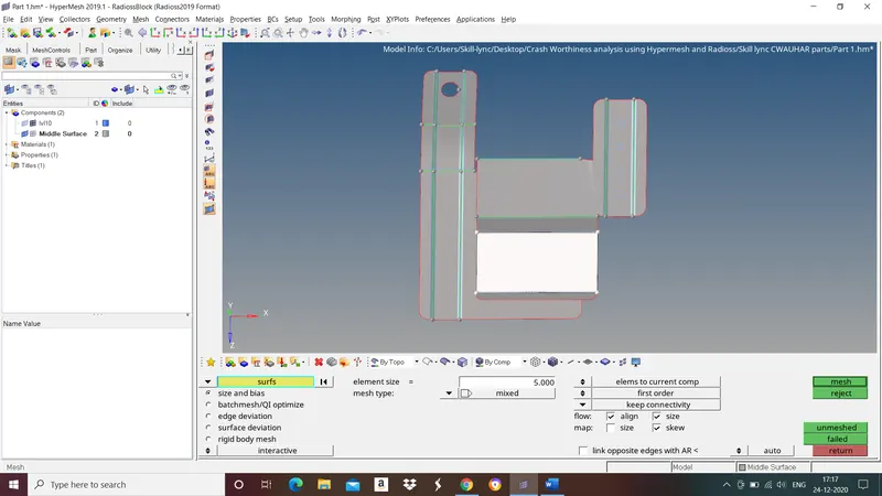
Select element type based on surface to get good mesh flow. Use mixed type mesh for irregular shaped surfaces, use quads mesh for rectangular and square shaped surfaces.
Avoid:
- Trias in corner or free edges.
- Opposite trias.
- Back to back trias.
- No trias in fillets or hemmings.
- Rotating quads.
- Trias share a boundary with feature line.
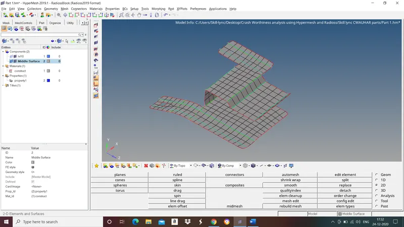
Fig: Final model
Now follow the same procedure for all the components.
2nd Component
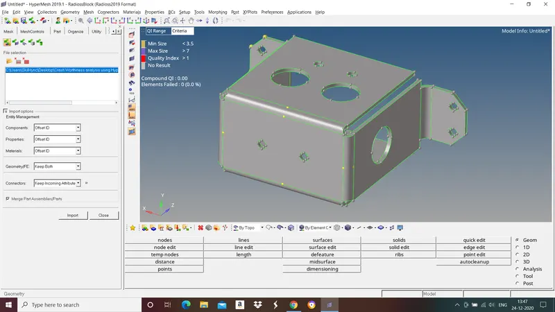
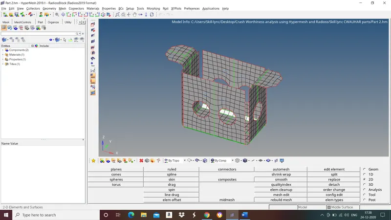
Fig: Final Model
3rd Component
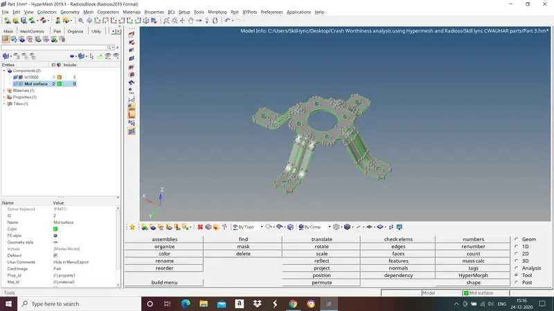
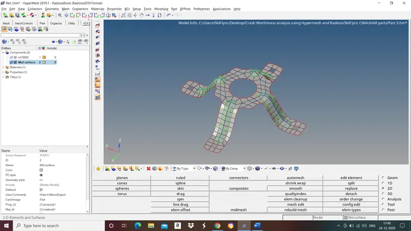
Fig: Final Model
LEARNING OUTCOME:
- Geometry Cleanup
- Mid surface extraction by automatic and manual method.
- Performing the 2D mesh.
CONCLUSION:
In this challenge we have followed all the steps involved in topology cleanup, Midsurface extraction, assigning thickness and meshing and obtained good mesh flow.