To connect different components using suitable connectors
AIM: To connect different components using suitable connectors.
METHODOLOGY:
- Import Geometry
- Geometry cleanup
- Midsurface extraction (for components having thickness less than 5mm) and Assign thickness
- Meshing
- Deploy connections
PROCEDURE:
1.Import Geometry:
Import geometry data via: Files > Import > Geometry drop down menu
Common types of geometry files supported:
• Unigraphics (NX2, NX3, NX4, NX5)
• UG Part Browser
•Import of *.prt files
• Requires an installation of Unigraphics to be available
• CATIA (V4 & V5)
• import of *.model files
• CATIA V5 license required to import
• V5 files
• Pro/ENGINEER (Wildfire 2.0 & 3.0)
• import of *.prt and *.asm files
• IGES
• Import of *.igs / *.iges files
• STEP
• import of *.stp file
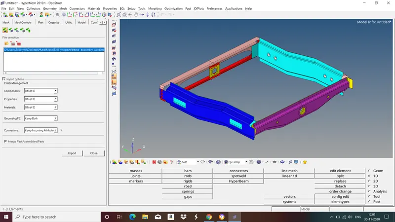
Fig : Given Model(frame assembly)
•Surface connectivity is controlled by the associated surface edges.
• If a surface edge is associated with more than 1 surface, those surfaces are considered to be connected (“equivalenced”).
• Surface edges are categorized, named, and colored according to the number of associated surfaces:
Free edge (red):
• Associated with only 1 surface
• Surfaces with a free edge between them are NOT equivalenced at that edge
Shared edge (green):
• Associated with 2 surfaces
• Surfaces are equivalenced
T-junction edge (yellow):
• Associated with 3 or more surfaces.
• Example: surfaces forming a T-connection.
• Surfaces are equivalenced.
Suppressed edge (blue):
• Surfaces are treated as though combined into 1 surface.
2.Topology Repair
HyperMesh will attempt to properly clean up surfaces during import
• Some types of geometry files have surface connectivity information which helps HyperMesh. Typically native geometry files like Catia, UG, ProE, etc.
Topology Repair consists of correcting connectivity errors between adjacent surfaces
Possible errors include:
• Unconnected adjacent surfaces
• Duplicate surfaces
• Missing surfaces
• Understand model size & scale to determine an appropriate global element size.
• Set a cleanup tolerance based on the determined global element size.
•Set appropriate value in options, geom cleanup, and automesh :cleanup.
•Cleanup tolerance specifies the largest gap size to be closed by topology functions.
• Tolerances > 15-20% of global element size can cause mesh distortions.
• Can change value multiple times for work on various areas of the model.
•Use topology display tools to decide what needs to be cleaned.
•Use equivalence to combine as many free edge pairs as possible.
• Make sure surfaces are not collapsed in undesirable manner.
•Use toggle to combine any remaining free edge pairs, 1 by 1
• use replace function if more control is needed.
•Use find duplicates to check for any duplicate surfaces and delete them.
•Use filler surface to recreate any missing surfaces.
The Goal of Topology Repair: Restore the surface data to a perfectly clean representation of the part.
3.Midsurface Extraction and Assign thickness
Components which are having thickness less than or equal to 5mm we take midsurface for those components and mesh it with shell elements.
The child component extracted should be an exact replica of parent component.
We can extract midsurface by both automatically and manually.
For Automatic midsurface extraction :
Go to Geom>midsurface>select auto midsurface and from drop down menu and select closed solid>select the surfaces>extract.
Sometimes auto midsurface may not proper result in that case we have to go with manual mid surface extraction.
For manual midsurface extraction :
Go to geom>surface edit>offset>select the surface and duplicate it and give offset value>offset.
Follow the same steps to extract midsurface for all the components.
After extracting mid surface we have to assign property, material and thickness for that mid surface.
To assign material go to tab bar right click>create>material>select newly created material and right click>edit>give material and its properties>close.
To assign property go to tab bar right click>create>property>select newly created property and right click>edit>give thickness and material>close.
Now goto tab bar, in components select mid surface component right click>edit>assign created property>close.
4.Meshing
A mesh is network that is formed of cells and points. It can have almost any shape in any size and is used to solve partial differential equations. Each cell of the mesh represents an individual solution of the equation which, when combined for the whole network, results in a solution for the entire mesh.
Before proceeding to meshing give element length and quality criteria. To do this go to Preferences in title menu bar>criteria file settings>give quality criteria>apply>close.
Give washer splits for holes to get good mesh flow.
Now start meshing surface by surface to get better mesh flow. To do this go to 2d>automesh>select the surface>select the element type>mesh.
5.Deploy Connections
Connectors: Connectors are geometric entities, which are primarily used to represent the CAD geometric connection in terms of FEA. Connections can be created as a spot weld, seam weld, adhsesive, bolts and masses. A realised connector will be considered as the successful representation of a CAD model in preprocessing and the connecting parts can be considered as connected.
1. To deploy Bolt connections
steps
- Goto 1D/2D>connectors>Bolt.
- In order to create a Bolt connection, if we had hole present in the components, we have to locate a centre node if not we have to change default option to 'create hole,if none'.
- Under 'location', select the node.
- Then select the 'comps' option under 'connect what',in order to create the weld between two components.
- Select the number of layers to be welded, under 'num layers' option.
- Specify the 'tolerence' value, based on the distance between the two components.
- select the type as 'bolt(general)'.
- Click on the 'create' button, to create the Bolt connection.
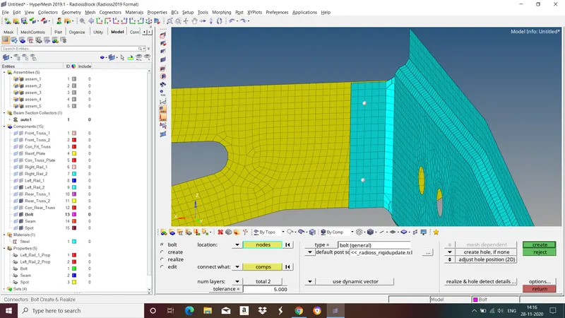
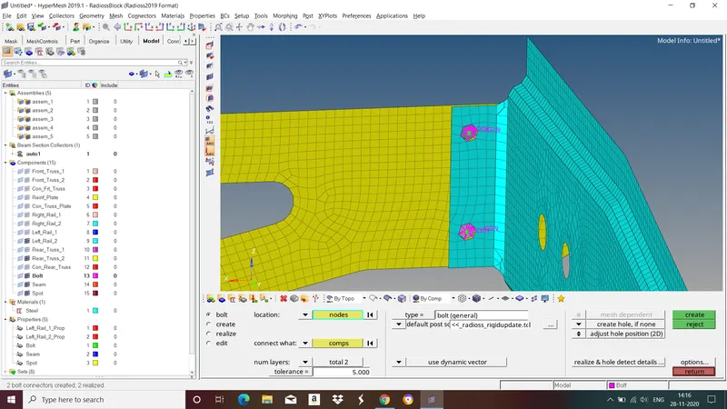
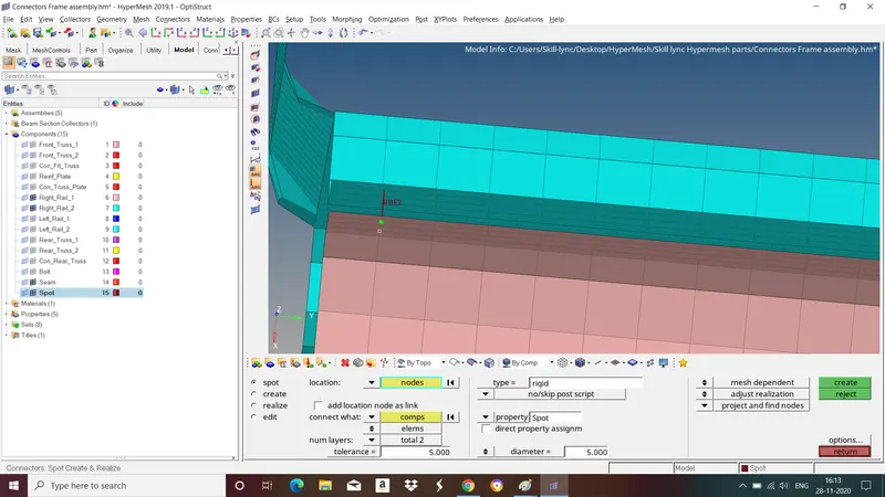
2.Spot weld with rigids elements
Steps
- Select 1D/2D>Connectors>Spot weld.
- Now select the location, where the weld has to be created, by clicking the 'node list'.
- Tick the checkbox of 'retain nodes' option, to retain the position of the nodes, while creating and realizing a connector.
- Specify the 'spacing' value and select the 'comps' option under'connect what' in order to create the weld between those components.
- select the number of layers(number of components) to be welded, under 'num layers' option.
- Specify the 'tolerence' value, based on the distance between the two components.
- Select the types as 'rigids'.
- Click on the 'create' button.
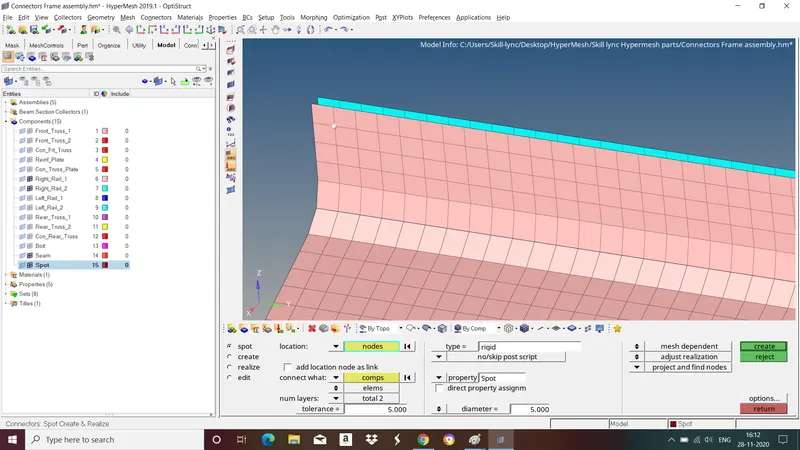
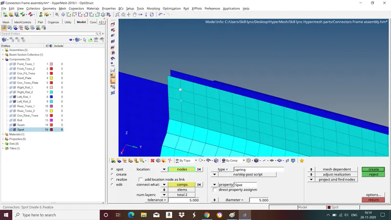
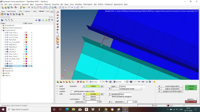
3.Spot weld with springs elements
Steps
- Select 1D/2D>Connectors>Spot weld.
- Now select the location, where the weld has to be created, by clicking the 'node list'.
- Tick the checkbox of 'retain nodes' option, to retain the position of the nodes, while creating and realizing a connector.
- Specify the 'spacing' value and select the 'comps' option under'connect what' in order to create the weld between those components.
- select the number of layers(number of components) to be welded, under 'num layers' option.
- Specify the 'tolerence' value, based on the distance between the two components.
- Select the types as 'springs'.
- Click on the 'create' button.
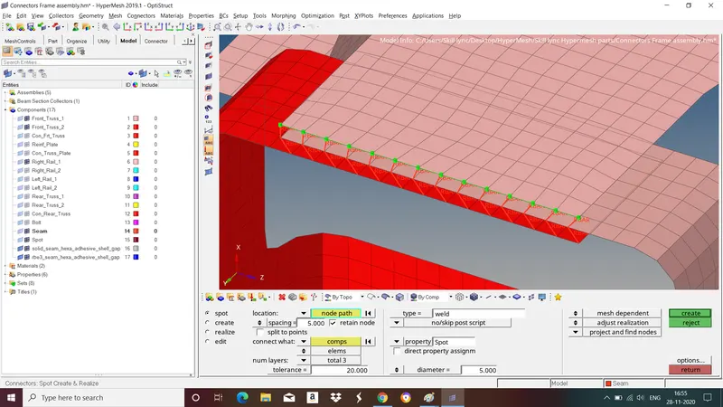
4.Spot weld with 3 layers and 5mm diameter elements
Steps
- Select 1D/2D>Connectors>Spot weld.
- Now select the location, where the weld has to be created, by clicking the 'node list'.
- Tick the checkbox of 'retain nodes' option, to retain the position of the nodes, while creating and realizing a connector.
- Specify the 'spacing' value and select the 'comps' option under'connect what' in order to create the weld between those components.
- select the number of layers(number of components) to be welded, under 'num layers' option and give diameter in diameter option.
- Specify the 'tolerence' value, based on the distance between the two components.
- Select the types as 'weld'.
- Click on the 'create' button.
5.Seam weld with quads elements
Steps
- Select 1D/2D>Connectors>Seam weld.
- Now select the location, where the weld has to be created, by clicking the 'node list'.
- Tick the checkbox of 'retain nodes' option, to retain the position of the nodes, while creating and realizing a connector.
- Specify the 'spacing' value and select the 'comps' option under'connect what' in order to create the weld between those components.
- Specify the 'tolerence' value, based on the distance between the two components.
- Select the types as 'quads'.
- Click on the 'create' button.

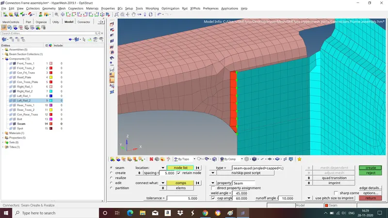
6.Seam-quad weld with angled+capped+L
Steps
- Select 1D/2D>Connectors>Seam weld.
- Now select the location, where the weld has to be created, by clicking the 'node list'.
- Tick the checkbox of 'retain nodes' option, to retain the position of the nodes, while creating and realizing a connector.
- Specify the 'spacing' value and select the 'comps' option under'connect what' in order to create the weld between those components.
- Specify the 'tolerence' value, based on the distance between the two components.
- Select the types as 'seam-quad weld with angled+capped+L'.
- Click on the 'create' button.
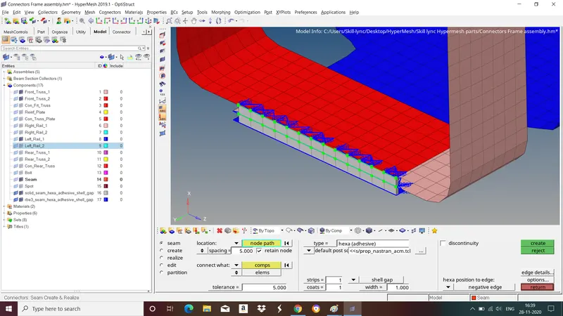
7.Seam weld with hexa adhesive elements
Steps
- Select 1D/2D>Connectors>Seam weld.
- Now select the location, where the weld has to be created, by clicking the 'node list'.
- Tick the checkbox of 'retain nodes' option, to retain the position of the nodes, while creating and realizing a connector.
- Specify the 'spacing' value and select the 'comps' option under'connect what' in order to create the weld between those components.
- Specify the 'tolerence' value, based on the distance between the two components.
- Select the types as 'hexa (adhesive)'.
- Click on the 'create' button.
Final Model:
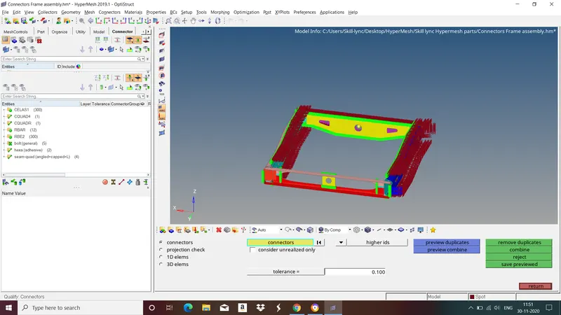
LEARNING OUTCOME: In this challenge we learned how to provide suitable connections between the components by using various connectors.
CONCLUSION: In this challenge we have followed all the steps invloved in connections and deployed suitable connectors between the components.