To Creat 1D elements on the following component with given cross-section and DOF
AIM : To Creat 1D elements on the following component with given cross-section and DOF.
METHODOLOGY :
- Import CAD Model
- Topology Repair
- Midsurface Extraction
- Assign material and property
- Meshing
- Create 1D Element
PROCEDURE :
Step 1 : Import CAD Model
Goto File>Import>Geometry>select the CAD file>Import.
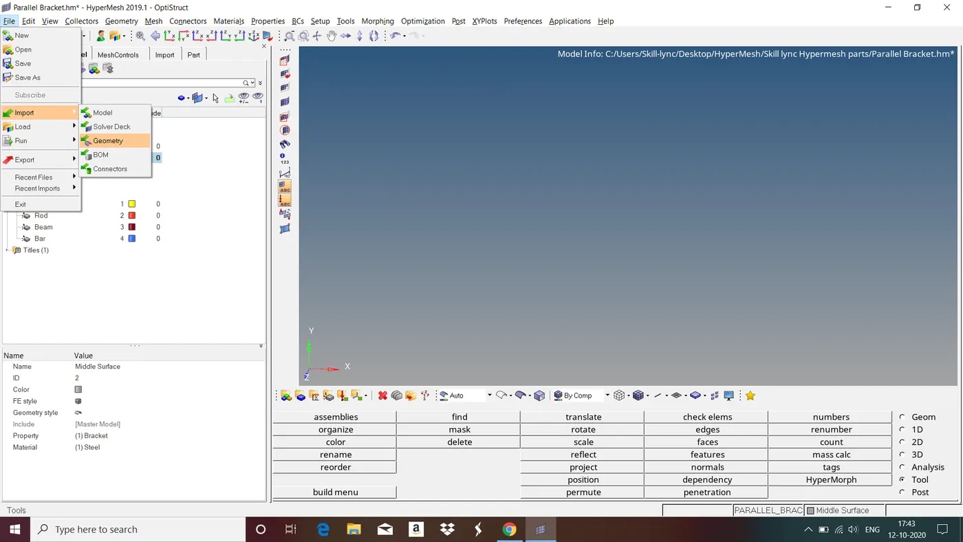
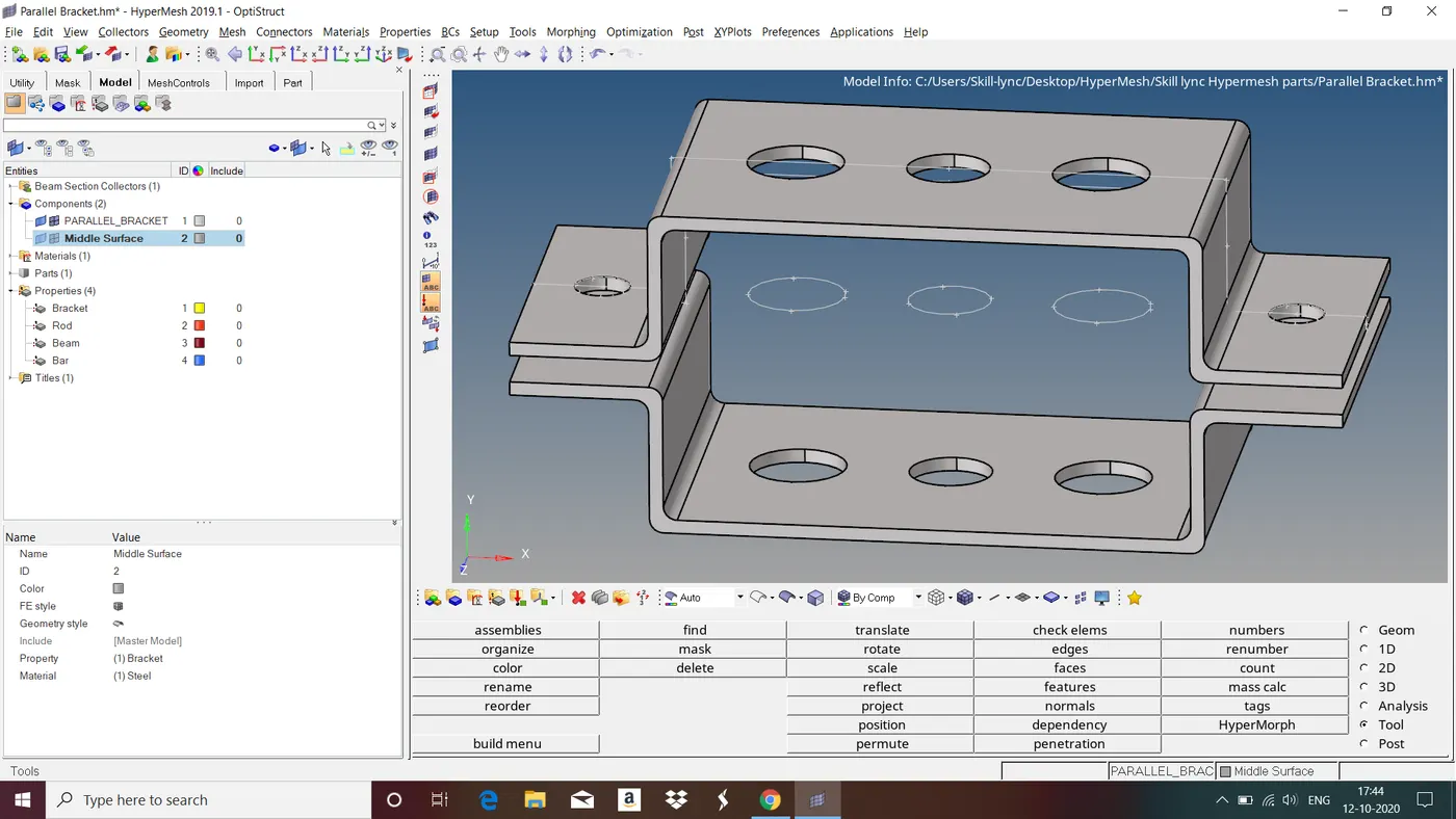
Fig : Given Component
Step 2 : Topology Repair
Topology Repair consists of correcting connectivity errors between adjacent surfaces. Possible errors include:
• Unconnected adjacent surfaces
• Duplicate surfaces
• Missing surfaces
The Goal of Topology Repair : Restore the surface data to a perfectly clean representation of the part.
Use the Autocleanup panel to perform automatic geometry cleanup and prepare your model for midsurface extraction.
To do this goto autocleanup in Geom>select the surfaces and give necessary parameters>autocleanup.
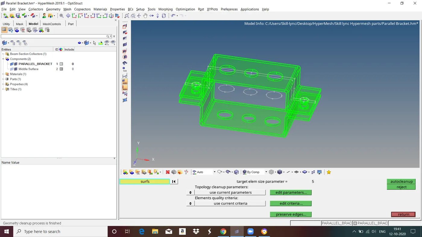
Fig : Performing geometry cleanup.
Geometry cleanup process is finished now the model is ready for midsurface extraction.
Step 3 : Midsurface Extraction
Components which are having thickness less than or equal to 5mm we take midsurface for those components and mesh it with shell elements.
To do this goto midsurface in Geom>select automidsurface>select the surfaces>extract.
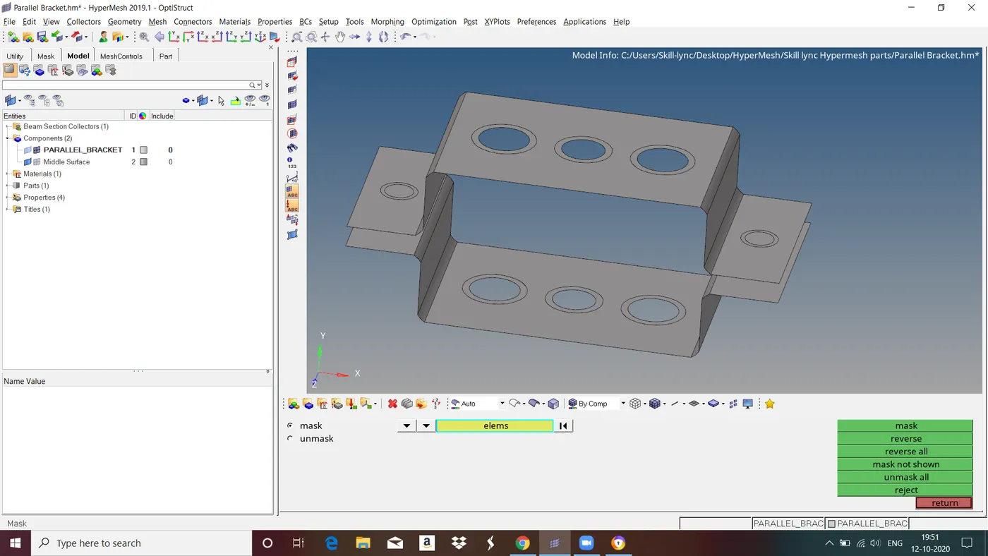
Fig : Midsurface
Step 4 : Assign Material and Property
After extracting midsurface we have to assign material, property, thickness,etc all the necessary parameters to that midsurface.
To assign material goto tab bar right click>select material>right click on created material select edit>in MAT section assign material>ok.
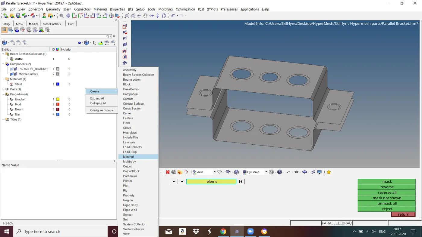
Fig : Assigning Material
To assign property goto tab bar right click>select property>right click on created property select edit>in T section give thickness of the component>ok.
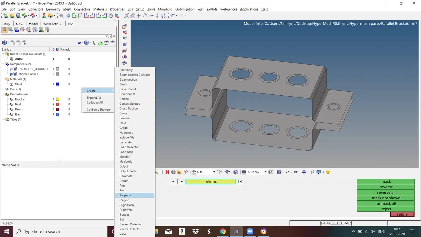
Fig : Assigning Property
After assigning material and property we have to assign these parameters to midsurface material and property. To do this right click on midsurface in tab bar and select assign>select property and select ok.
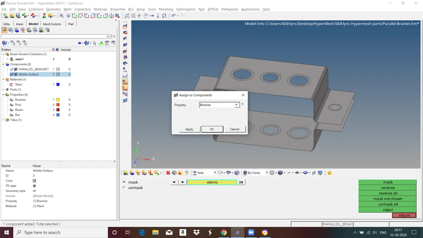
Fig : Assigning property to the midsurface.
Follow the same steps to assign the material and property for the parts wherever required.
Step 5 : Meshing
A mesh is a network that is formed of cells and points. It can have almost any shape in any size and is used to solve Partial Differential Equations. Each cell of the mesh represents an individual solution of the equation which, when combined for the whole network, results in a solution for the entire mesh.
Before meshing we have to give washer split for holes. To do this goto quick edit>select washer split and give offsete value>select the hole edge to washer split.
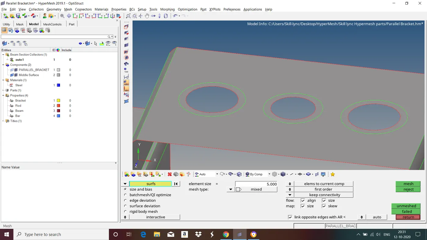
Fig : Holes after creating washer split.
Now start meshing. To mesh goto 2D in main menu page>select automesh>select the surfaces and give all the necessary parameters>mesh.
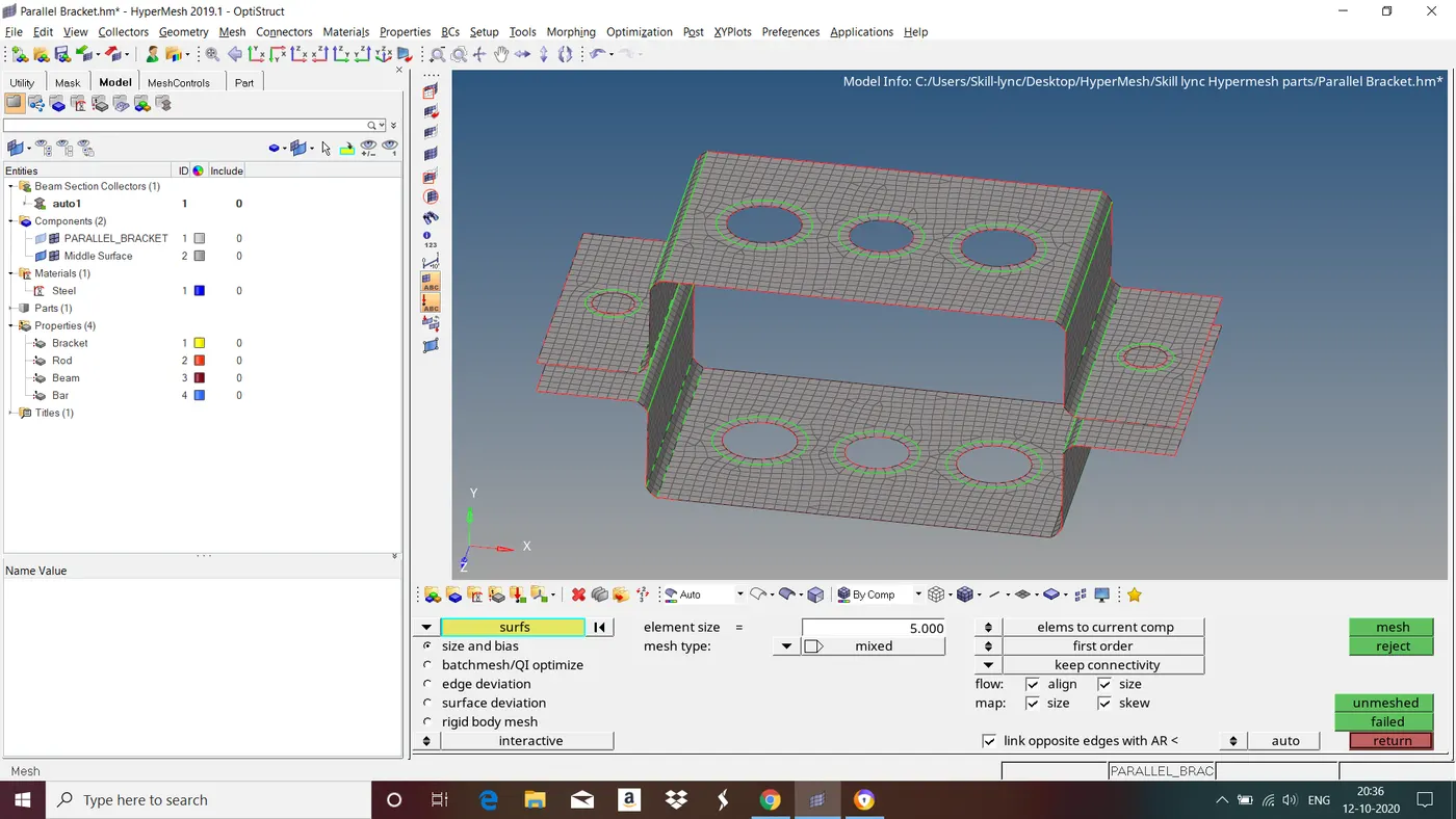
Fig : Component after meshing.
Step 6 : Create 1D Element
1D elements referred to as line elements. Often used to represent the members which are too long compared to the measurement of cross-section. We have to provide 1D element for the given component as per the given dimensions.
a. Rod element:- with only translational DOF and RBE2 link
Cross-Section: BOX- Dimension a= 12 mm
dimension b=10 mm
Thickness t= 0.75 mm
b. Beam element:- with all DOF and RBE3 link
Cross-Section: I Section- Dimension a= 8 mm
Dimension b= 10 mm
Dimension c= 8.5 mm
Thickness t1= 0.75 mm
Thickness t2= .6 mm
Thickness t3= .6 mm
c. Bar element:- with only x and y DOFs With RBE3 link
Cross-section: CROSS section- Dimension DIM1= 5 mm
Thickness DIM2= 1.2 mm
Dimension DIM3= 10 mm
Thickness DIM4= 1.2mm
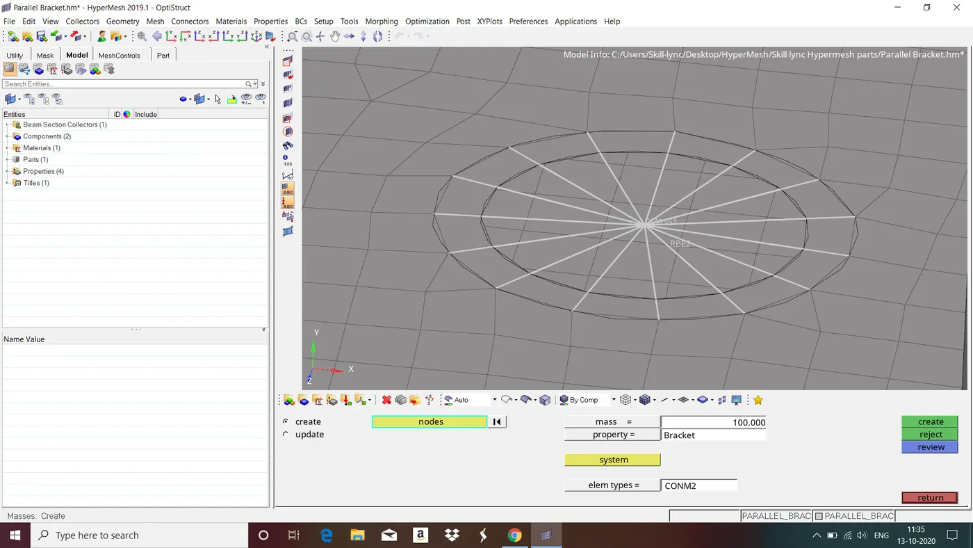
d. & e. apply the mass of magnitude 10 with RBE2 link
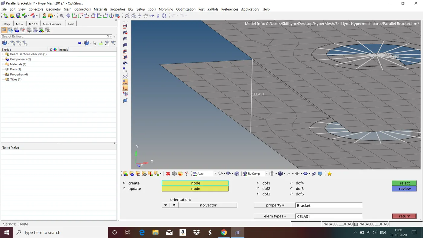
f. Join the two components with Spring elements
Before providing rod,beam and bar elements we have to provide REB2 and RBE3 elements.
To give RBE2 elements goto 1D in main munu page>rigids>select the nodes and give dof>create.
To give RBE3 elements goto 1D in main menu page>rbe3>select the nodes and give dof>create.
Follow the same steps to provide RBE2 and RBE3 elements wherever required.
1. For Rod element :
a. Goto 1D in main menu page>HyperBeam>select standard section>create>in HyperBeam view, in Tab bar right click>create>standard section>optistruct>Box>give all the necessary dimensons.
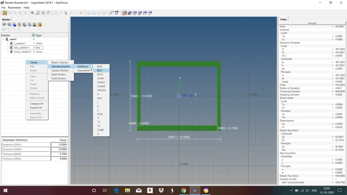
Fig : Creating Box cross section.
b. Then we have to assign material and property for the rod element by following same steps as explained in above.
c. goto 1D in main menu page>rods>select the nodes,select element type and element property>middle click.
2. For Bar elements
a. Goto 1D in main menu page>HyperBeam>select standard section>create>in HyperBeam view, in Tab bar right click>create>standard section>optistruct>Cross>give all the necessary dimensons.
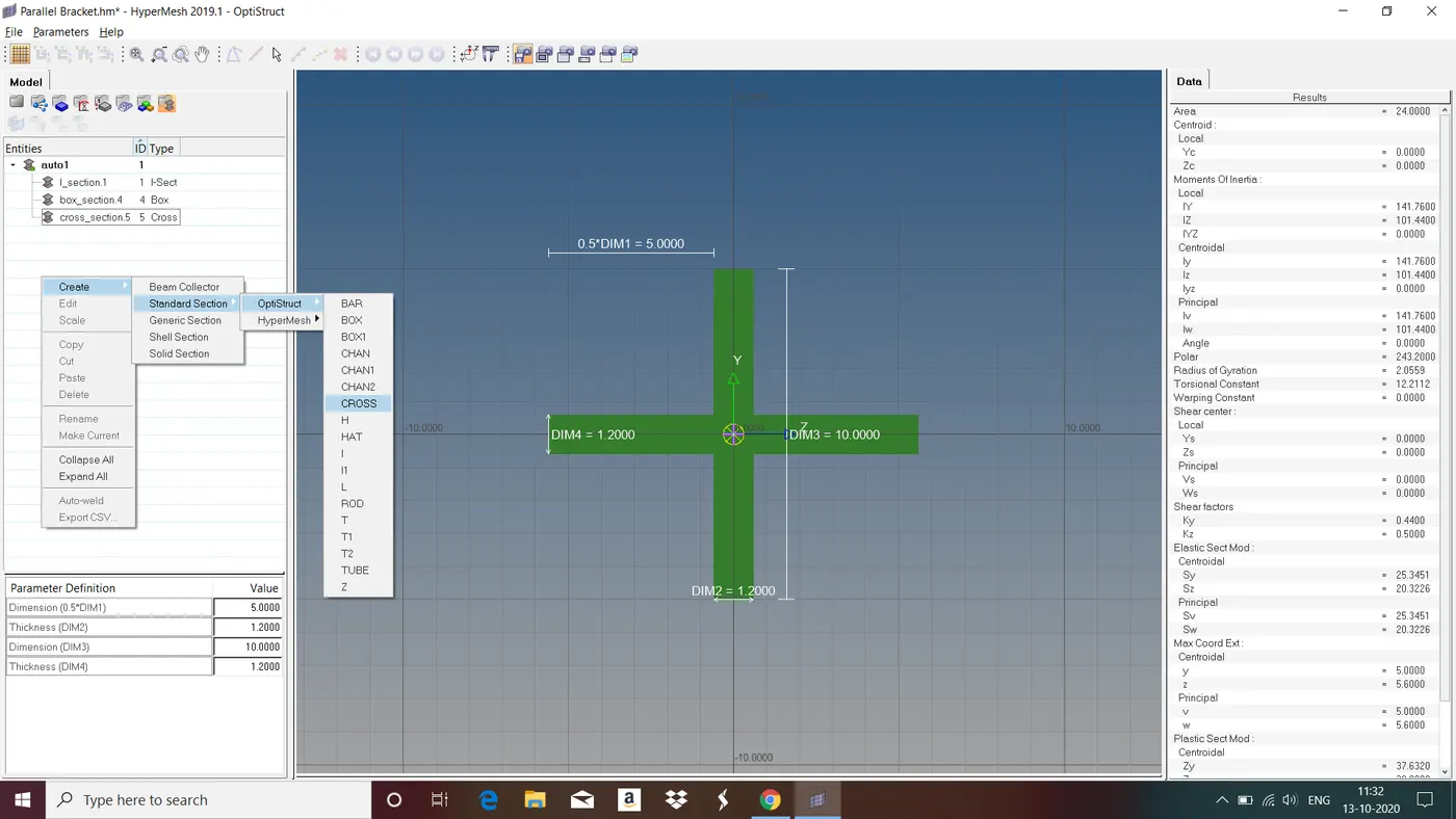
Fig : Creating Cross cross section.
b. Then we have to assign material and property for the rod element by following same steps as explained in above.
c. goto 1D in main menu page>bars>select the nodes,select element type as cbar,element property and node vector>middle click.
3. For Beam element
a. Goto 1D in main menu page>HyperBeam>select standard section>create>in HyperBeam view, in Tab bar right click>create>standard section>Hypermesh>I section>give all the necessary dimensons.
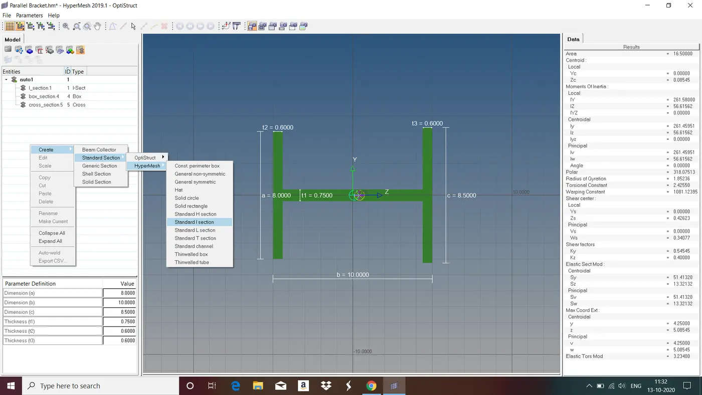
Fig : Creating I cross section.
b. Then we have to assign material and property for the rod element by following same steps as explained in above.
c. goto 1D in main menu page>bars>select the nodes,select element type as cbeam,element property and node vector>middle click.
4. To apply the mass
Goto 1D in main menu page>masses>select node,give mass,element property and element type>middle click.
5. To give spring element
Goto 1D in main menu page>springs>select the nodes,dof,element property and element type>middle click.
FINAL MODEL :
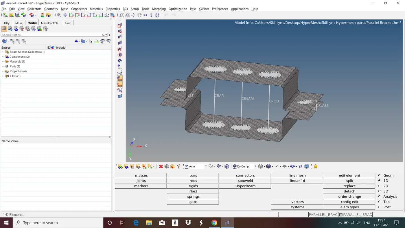
Fig : 1D and 2D traditional element representation of final model.
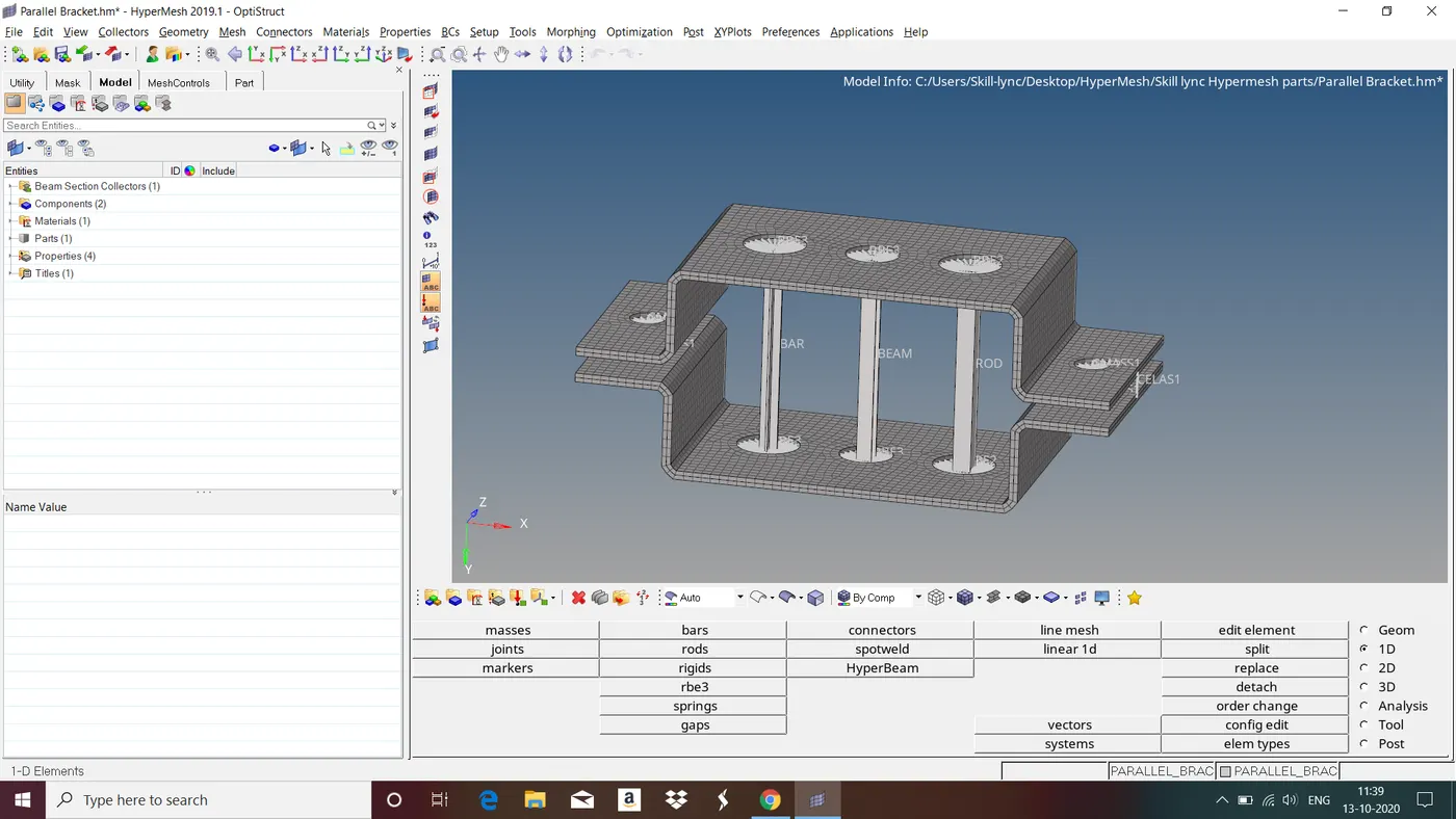
Fig : 1D and 2D detailed element representation of final model.
LEARNING OUTCOME : In this objective we have learned all the steps involved in creating 1D element.
CONCLUSION : In this objective we have followed all the steps involved in creating 1D element and we provided 1D element to the given component wherever required.