Week 9-Creation of 1D Connectors Challenge
#9 Week Challenge Hyper-mesh for FEA Plastic and Sheet Metal Applications
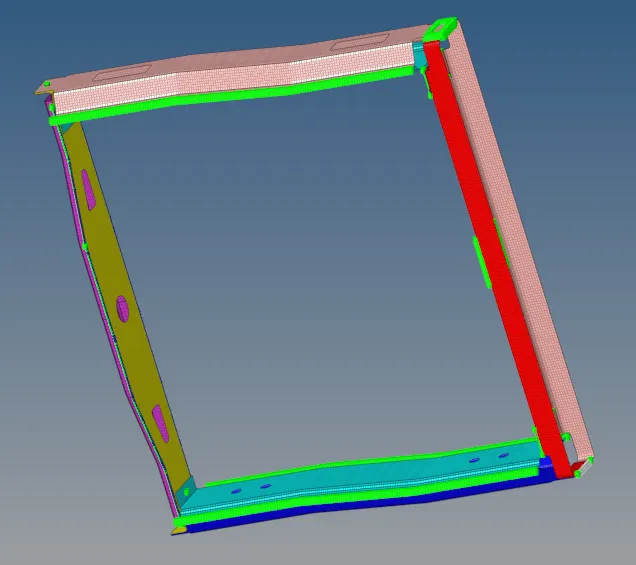
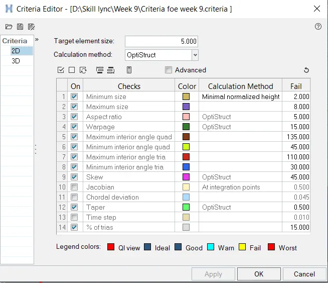
Aim: To Mesh the given components by giving the target Element Length as "5 units" by using the quality criteria as below:
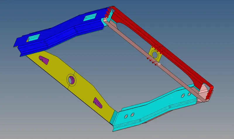
Import the geometry;
- Click on the import icon on the main menu bar.
- Select the import geometry and choose the file, click on import.
- Then the file will be imported and will be shown in the graphical area as below,
2D Meshing:
- Click on the 2D from the menu bar.
- Click on auto-mesh and enter the target element size as 5 units.
- Select the type as tria elements, give the minimum and maximum element length in the criteria file.
- Click on the surfaces and select the displayed surfaces, make sure the component is made as current component.
- Click on create mesh, check for the elements failed and re-mesh the elements.
- Check the elements for quality before starting the connectors,
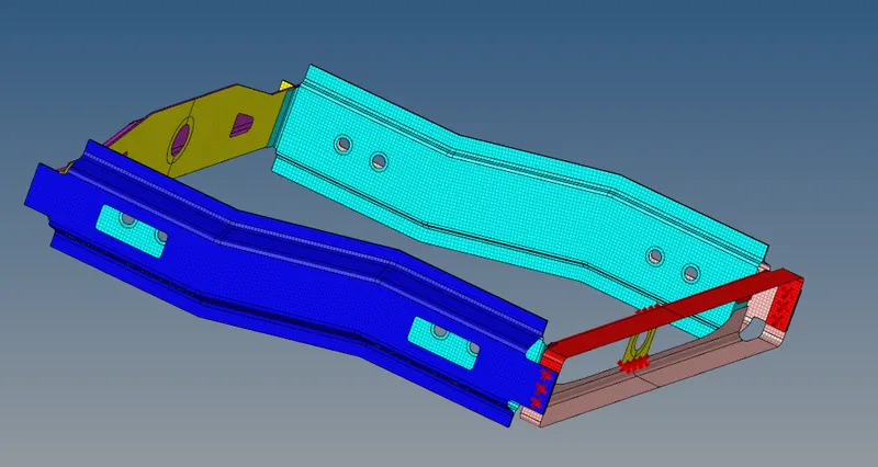
Connector Rules:
- Connectors has to be created at the component attachments.
- Click on create, you can see the connector is created, realised in the status bar.
- Open the connector from the view >browser > Hypermesh > Connector, here you can see the connectors that has been created.
- Red indicates the connector is created but not realised.
- Green indicates the connector is created and also realized.
- Every connector created must be realised.
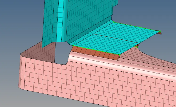
Task-1: Right_Rail_2 & Front_truss_1:- Seam-Quad(angled+capped+L)
- Go to 1D panel from the menu bar.
- Click on connectors and click on seam from the 1D menu bar.
- Hide the other components except the component to be connected and make one of them as current component.
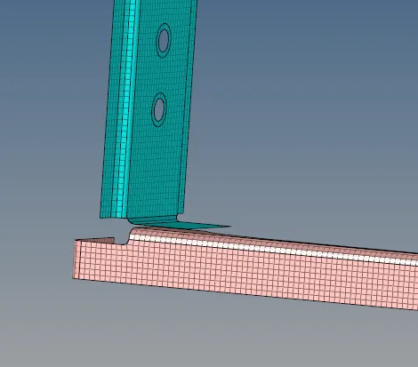
- Click on seam, select the nodes where the connector has to be created.
- Select the type of connector by clicking on type and select it as Seam Quad (Angled+capped+L).
- Set the tolerance value to 10(based on the distance between 2 components) spacing is same as the target element size of mesh.

- Select the components to those the connectors has to be created, change the imprint to skin imprint.
- Click on create, you can see the number of connectors created and realised in the status bar.
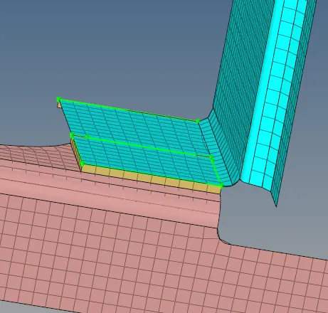
Task-2: Left_Rail_2 & Front_truss_1:- Quad elements
- Go to 1D panel from the menu bar.
- Click on connectors and click on seam from the 1D menu bar.
- Hide the other components except the component to be connected and make one of them as current component.
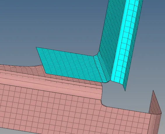
- Click on seam, select the nodes where the connector has to be created.
- Select the type of connector by clicking on type and select it as Quads.
- Set the tolerance value to 10(based on the distance between 2 components) spacing is same as the target element size of mesh.

- Select the components to those the connectors has to be created, change the imprint to skin imprint.
- Click on create, you can see the number of connectors created and realised in the status bar.
Task-3: Front_truss_2, Front_truss_1 & Right_Rail_1:- Spot weld with 2 Layers and 5 mm Diameter
- Go to 1D panel from the menu bar.
- Click on connectors and click on spot from the 1D menu bar.
- Hide the other components except the component to be connected and make one of them as current component.
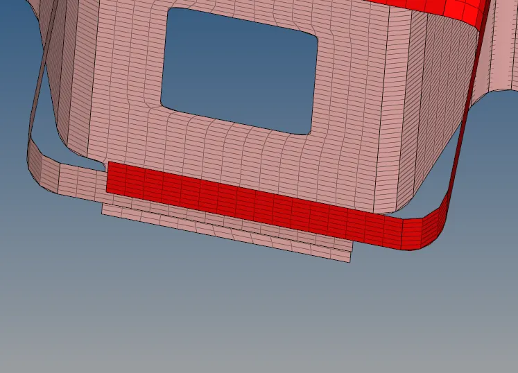
- Click on spot,select the nodes where the connector has to be created.
- Select the type of connector by clicking on type and select it as Weld.
- Set the tolerance value to 10(based on the distance between 2 components) spacing is same as the target element size of mesh.
- Set the layers as 2, and the diameter is 5mm.

- Select the components to those the connectors has to be created.
- Click on create, you can see the number of connectors created and realised in the status bar.
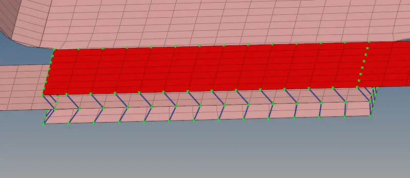
Task-4: Front_truss_2, Front_truss_1 & Left_Rail_1:- Hexa (Adhesive)
- Go to 1D panel from the menu bar.
- Click on connectors and click on seam from the 1D menu bar.
- Hide the other components except the component to be connected and make one of them as current component.
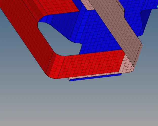
- Click on seam, select the nodes where the connector has to be created.
- Select the type of connector by clicking on type and select it as Hexa(Adhesive).
- Set the tolerance value to 10(based on the distance between 2 components) spacing is same as the target element size of mesh.

- Set the layers as 2, and the width based on the components.
- Select the components to those the connectors has to be created.
- Click on create, you can see the number of connectors created and realised in the status bar.
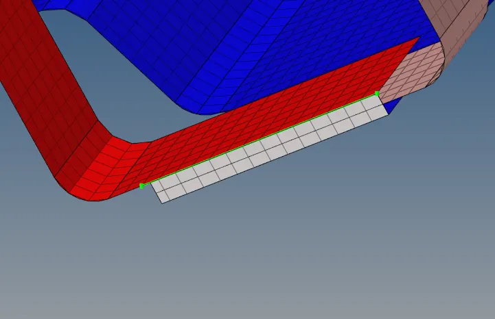
Task-5&6: (Rear_truss_2 & Right_Rail_2 ),(Rear_truss_2 & Left_Rail_2):- Bolt Connector
- Go to 1D panel from the menu bar.
- Click on connectors and click on bolt from the 1D menu bar.
- Hide the other components except the component to be connected and make one of them as current component.
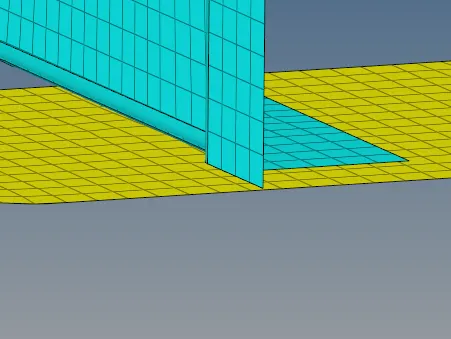
- Click on Bolt, select the nodes where the bolt connector has to be created.
- Select the type of connector by clicking on type and select it as bolt(general).
- Set the tolerance value to 10(based on the distance between 2 components) spacing is same as the target element size of mesh.

- Select the components to those the connectors has to be created, select the create if hole none from the dropdown menu
- Click on create, you can see the number of connectors created and realised in the status bar.
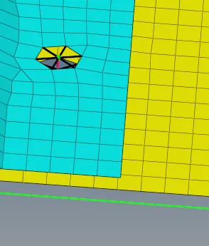
Task-7:Right_Rail_1 & Right_Rail_2:- Spot-weld with Rigid Elements
- Go to 1D panel from the menu bar.
- Click on connectors and click on spot from the 1D menu bar.
- Hide the other components except the component to be connected and make one of them as current component.
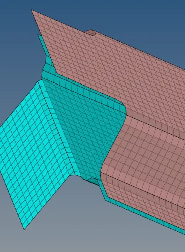
- Click on spot, select the nodes where the connector has to be created.
- Select the type of connector by clicking on type and select it as Rigids.
- Set the tolerance value to 10(based on the distance between 2 components) spacing is same as the target element size of mesh.

- Select the components to those the connectors has to be created.
- Click on create, you can see the number of connectors created and realised in the status bar.
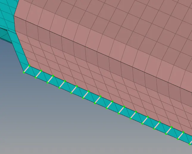
Task-8: Left_Rail_1 & Left_Rail_2:- Spot-weld with Spring Elements
- Go to 1D panel from the menu bar.
- Click on connectors and click on spot from the 1D menu bar.
- Hide the other components except the component to be connected and make one of them as current component.
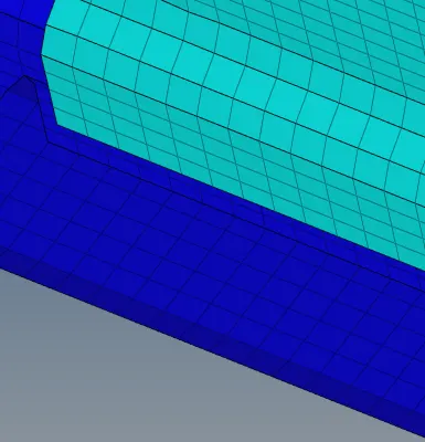
- Click on spot, select the nodes where the connector has to be created.
- Select the type of connector by clicking on type and select it as Springs.
- Set the tolerance value to 10(based on the distance between 2 components) spacing is same as the target element size of mesh.

- Select the components to those the connectors has to be created.
- Click on create, you can see the number of connectors created and realised in the status bar.
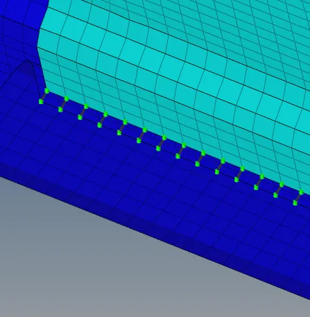
Task-9: Rest all the component left Joined them with suitable connectors
Joined them with springs, welds, quads suitable to the components
The Output: