Week 7-Long Piston With Cam
#7 Week Assignment- Introduction to Ansys Workbench
Aim:To run the analysis for Long piston with Cam on a total of 3 different cases with change in friction terms and provide the inference on the output.
Objective:
- Import the Geometry to Transient Structural
- Case setup (Contacts, Meshing,Analysis settings,joints,)
- Run the analysis
- Set the output parameters required.
- Run for the remaining cases
- Comparison for 3 cases.
- Inference with output files.
Setup:
- Open Ansys Workbench and select the Transient Structural.
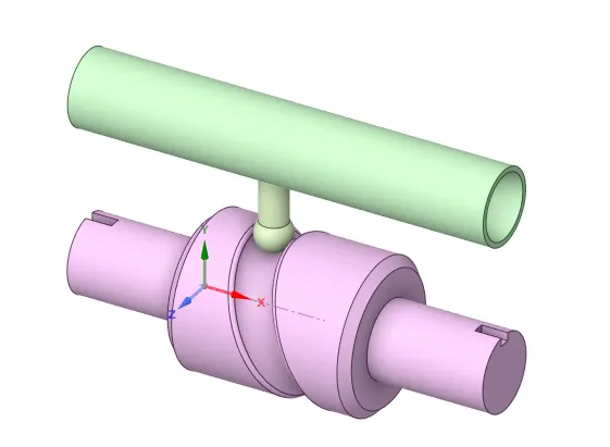
- Import the geometry and open the spaceclaim to check for geomtery checkup.
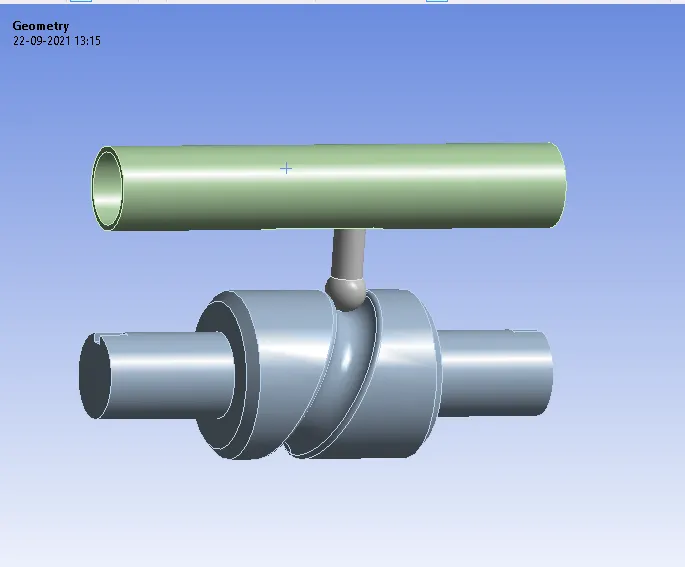
- Then open the mechanical module and the model can be seen in graphical area as below,
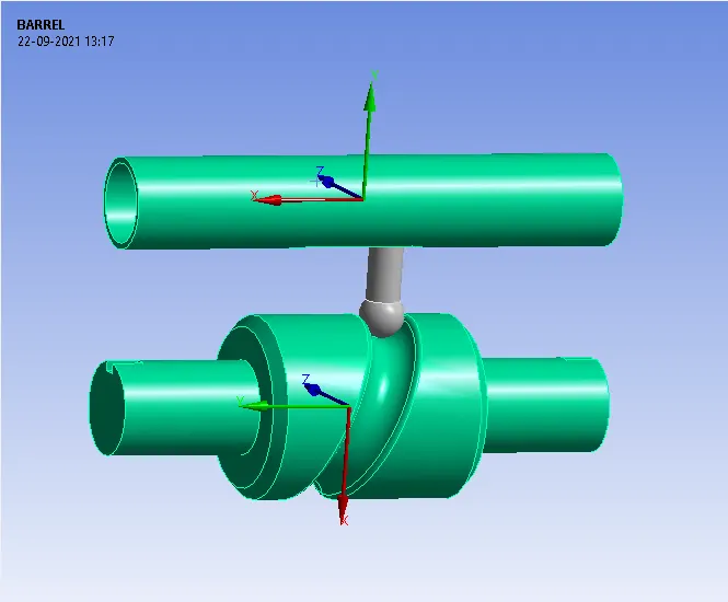
- Set the stifness behaviour to Rigid for both the barrel and the barrel cam.
Meshing:
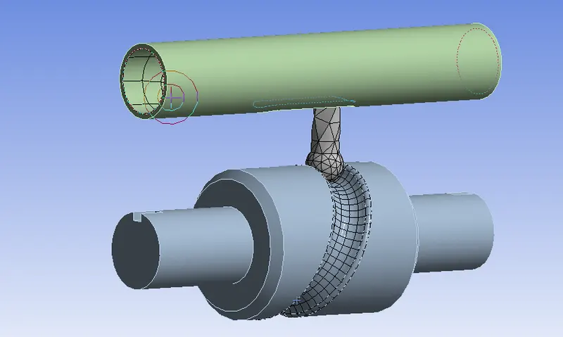
- Select the faces that goes into contact and insert sizing for them to get best results prefarably for that areas.
- Turn of the adaptive sizing in the mesh window.
- Mesh will not be generated on the rigid bodies as they are under point loads.
Contacts:
- Goto Contacts in connections and flip the existed contacts so that it would be meaningful for thr the simulation.
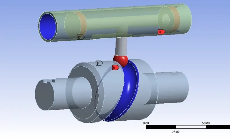
- Create the joints that are reuired for the motion of the simulation.
- Create a Fixed joint to constrain the motion of the Barrel.
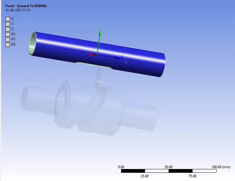
- Create a Revolute joint for the Barrel cam for it's revolute motion.
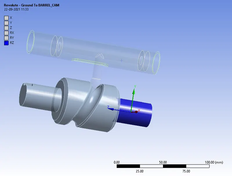
- Create a Traslational joint for body to body and select the mobile bodies as the face of the body inside the barrel and reference as the face of the outer barrel.
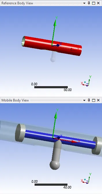
Transient Analysis Settings:
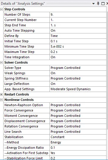
- The simulation has to be runned for a total of 9 steps, the steps to be set as below,
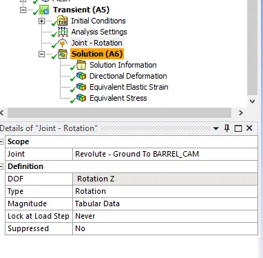
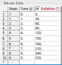
- Create a Joint rotation for revolute ground to barrel and insert the tabular data as following,
CASE-1:
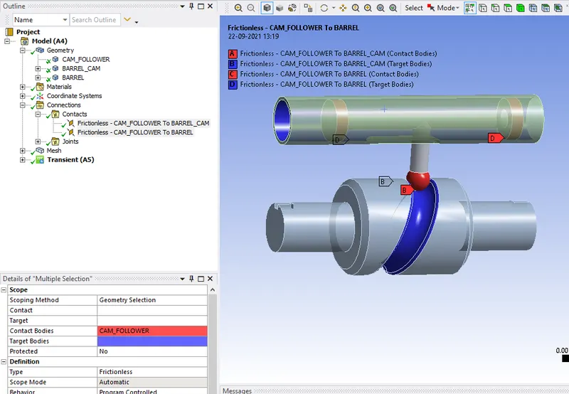
- Goto contacts and select the 2 contacts and set the type of contact as frictionless.
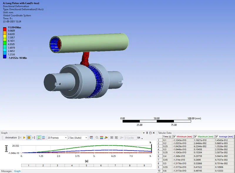
Directional Deformation:
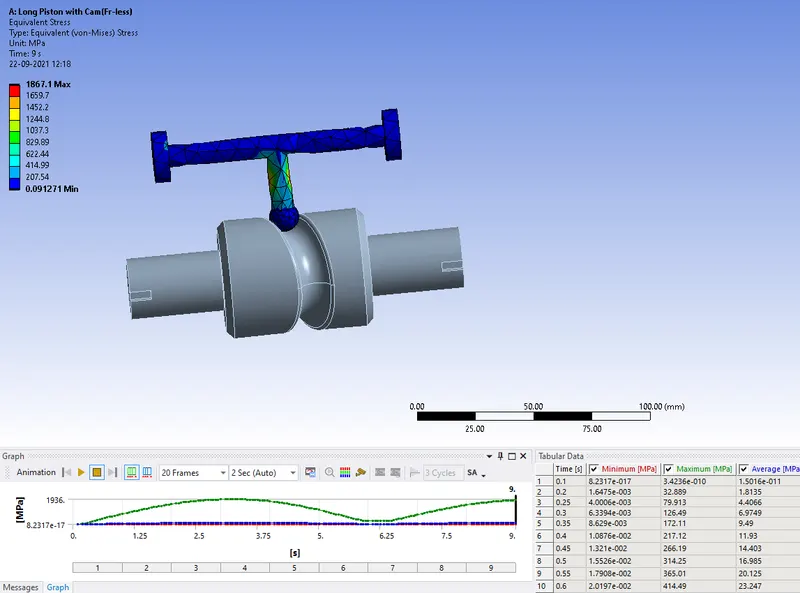
Equivalent Stress:
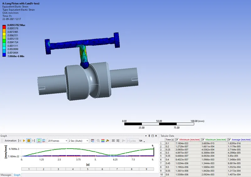
Equivalent Strain:
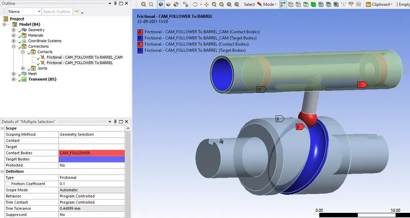
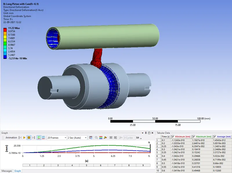
CASE-2: Change the contact for the connections as frictional and friction coefficient to be 0.1.
Directional Deformation:
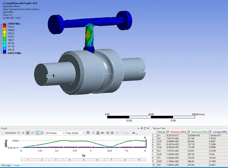
Equivalent Stress:
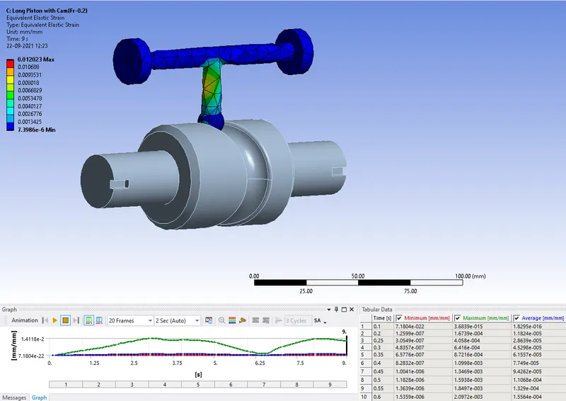
Equivalent Strain:
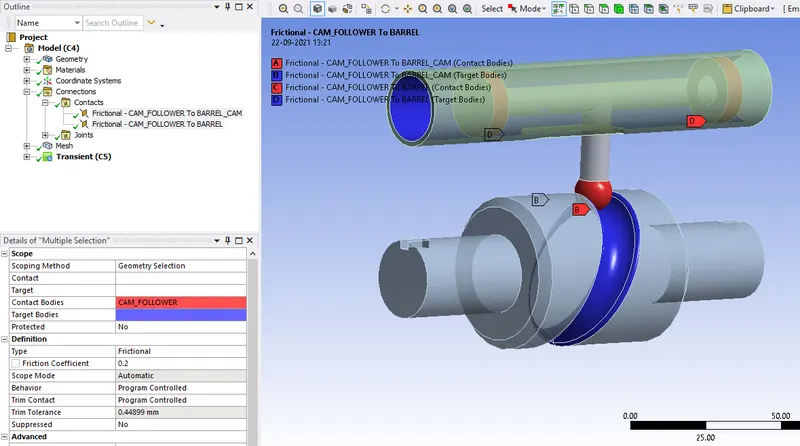
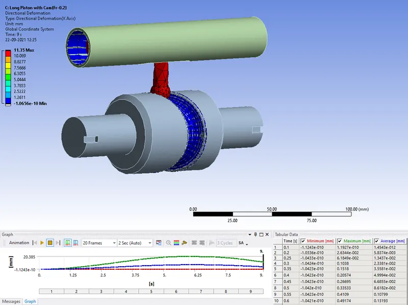
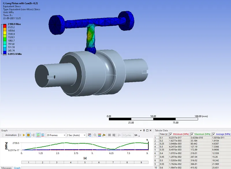
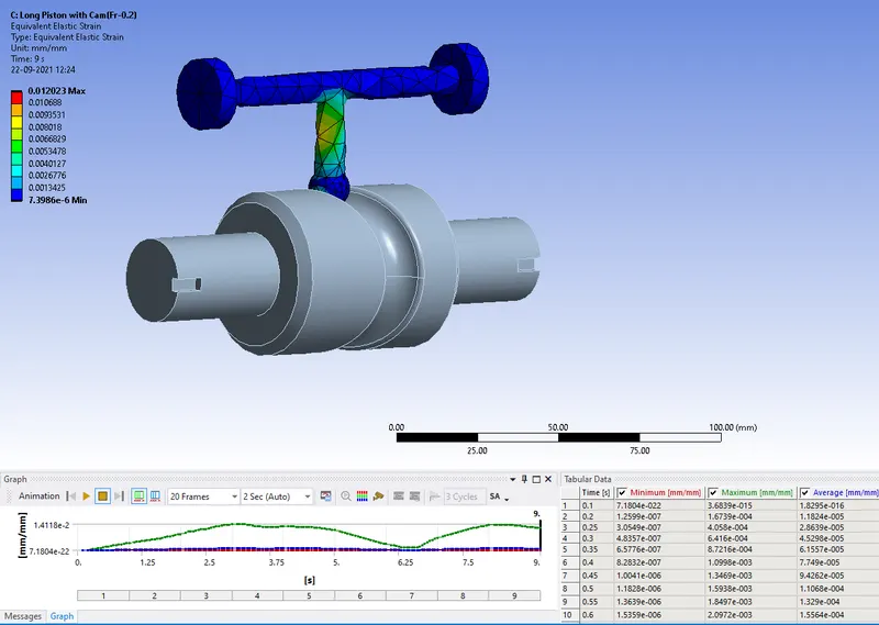
CASE-3: Change the contact to be fricttional and friction coefficient to be 0.2 and evaluate the results.
Directional Deformation:
Equivalent Stress:
Equivalent Strain:
Comparison:
| Max. values are presented | Directional Deformation-X Axis(mm) | Eq.Stress (MPa) | Eq.Strain |
| Case-1 (Fric-less) | 11.094 | 1867.1 | 0.0093 |
| Case-2 (Fric coeff-0.1) | 11.22 | 2130.5 | 0.010 |
| Case-3 (Fric coeff-0.2) | 11.35 | 2390.9 | 0.012 |
Conclusion:
From the above setup for the 3 cases varies only in the frictional terms, the friction effects the contact of the bodies which develops stress and strain.
For Directional deformation: As most of thye movemenrt is in the X-direction this result has to be observed which gave result that there's a minor devolopement for the 3 cases.
For the Equivalent Stress: There's a significant change in stress for the 3 cases i.e frictionless contact, frictional contact with coefficient of friction 0.1 & 0.2.
For the Equivalent Strain: The equivalent strain for the 3 cases rises gradually with change of contact from frictionless to frition with with increasing friction coefficient.
Note: All the values for the parameters that are analyzed for th long piston with cam has been increased with increase in friction. From the above simulation,
"Friction coefficient is directly proportional to stress and strain".