Assignment 6-Frontal Crash Simulation Challenge
#6 Assignment Crashworthiness Analysis using Hypermesh and Radioss
OBJECTIVE:-
- To perform the frontal crash simulation follow the given conditions
- Frontal crash-BIW
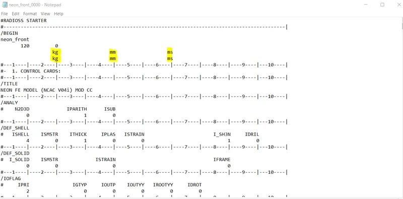
- Check unit system and either follow[Mg mm s] or [Kg mm ms].
- Create an appropriate interface, friction 0.2 and recommended parameters.
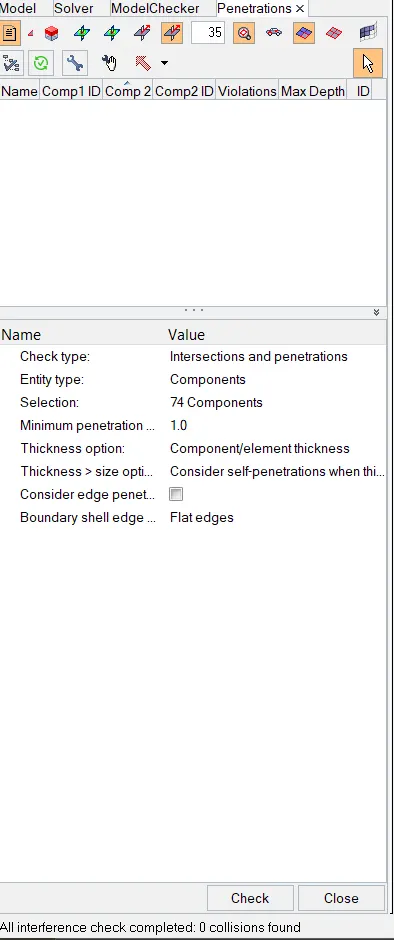
- Make sure of no penetrations and intersection.Correct rigid bodies if any issues.
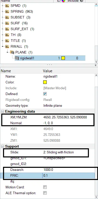
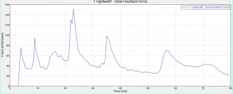
- Create a rigid wall with friction 0.1.
- Compare the model weight with the full-scale 300k nodes model and use added masses to reach the target weight of
700kg while getting CG about the required range. - Initial velocity 35 mph.
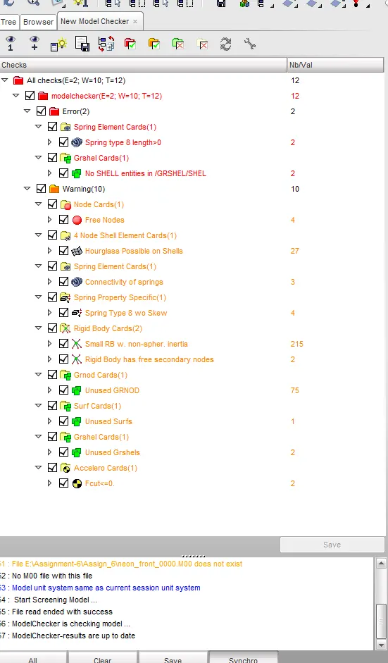
- Use a model checker to ensure good quality.
- Time-step :0.5 to 0.1 microseconds.
- Run 80 ms.
Output requests: - Sectional force in the rails at the location of indicated node 174247.
- The axial force received on the rails from the bumper.
- Shotgun cross-sectional forces.
- A pillar cross-section.
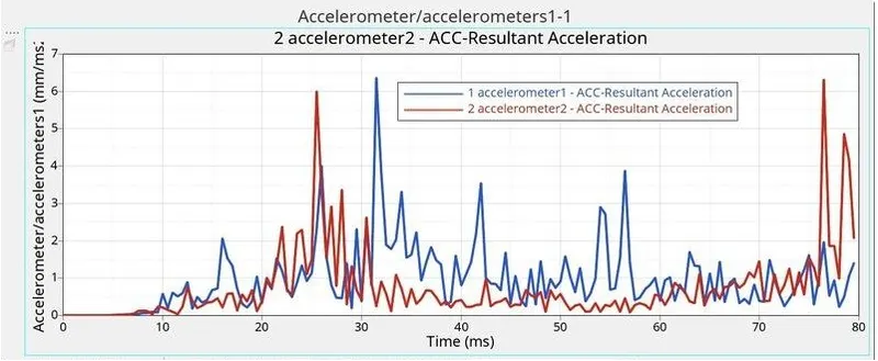
- Acceleration curve received on the accelerometer at base of B pillar (on B pillar rocker).
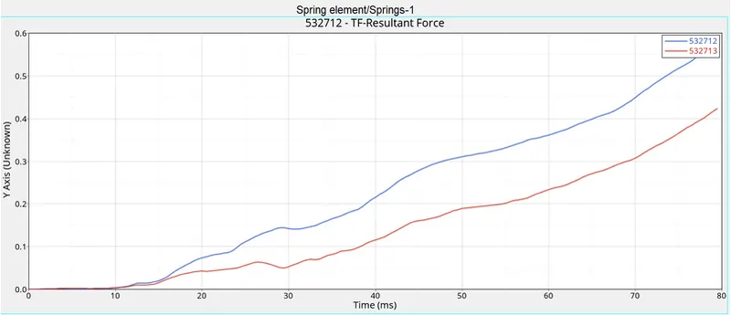
- Intrusions on the dash wall 66695,66244.
CASE SETUP AND EXECUTION:-
- First import the Radioss file in the Hypermesh.
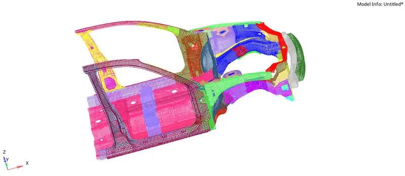
CHECK THE UNIT SYSTEM:-
- Open the Radioss starter file in note pad see the units.
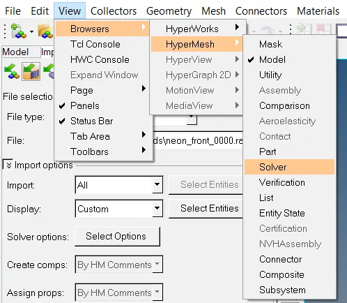
CREATE THE INTERFACE:
- Goto the menu bar select View>Browser>Hypermesh>Solver.
- In the solver right click on the inter Create>TYPE7.
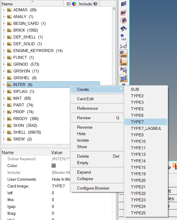
TYPE7:-
→ Type7 is a node to surface contact.
→ It is a general-purpose interface and can simulate all types of impact between a set of nodes and a master surface.
→ It is used in any applications.
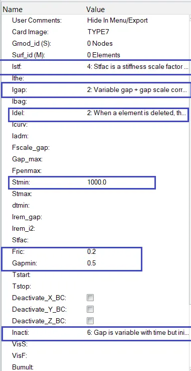
set the given properties
→ Istf is set stiffness of interface based on the softer of master and slave.
Istf=4 (stfac is a stiffness scale factor and interface stiffness is computed from both main and secondary characteristics).
→ Igap is a set variable gap to take into account the true distance between parts.
Igap=2 (variable gap+gap scale correction of the computed gap).
→ Idel is removing slave nodes from contact because of element selection.
Idel=2 (when an element deleted, the corresponding segment is removed from the main side of the interface).
→ Stmin has specified a minimum stiffness in the contact to avoid too-soft contact.
Stmin=1000N/MM
→ Fric=0.2
→ Gapmin is specified minimum thickness of the model to avoid numerical issues.
Gapmin=0.5
→ Inacti is to remove initial penetrations where possible. Elsewhere, reduce to less than 30%of the defined gap value and adjust the gap with Inacti.
Inacti=6 (Gap is variable with time but initial penetration is computed).
→Iform is sliding forces are computed using the stiffness parameter of the interface. Usually results in a bigger time step.
Iform=2 stiffness (incremental) formulations.

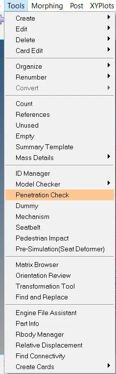
CHECK FOR NO PENETRATIONS AND INTERSECTIONS:
- Goto menu bar select the Tools>penetration check.
- Open the penetration panel in the tab bar shown below.
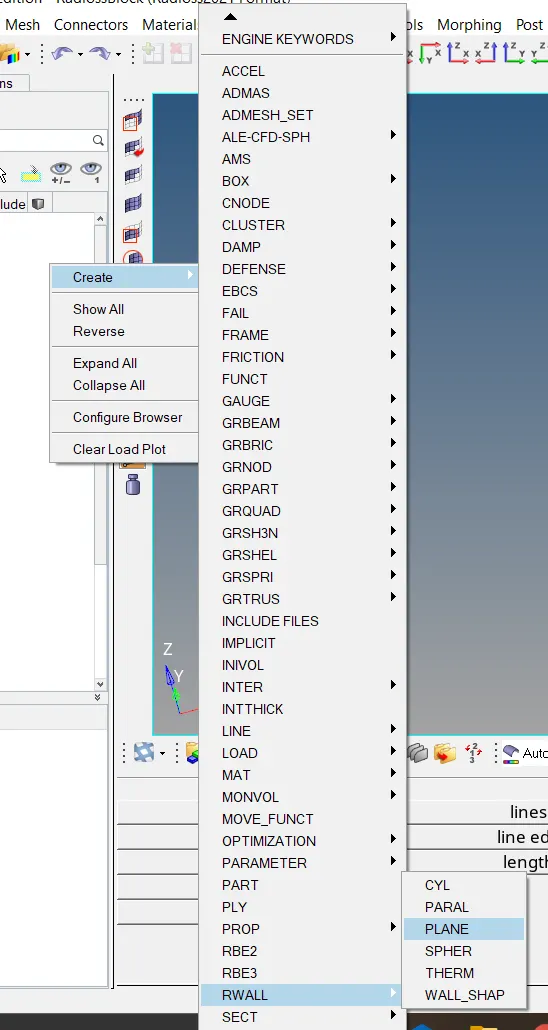
CREATE RIGID WALL WITH FRICTION 0.1:
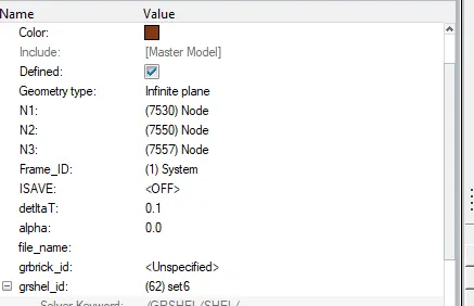
- Goto tab bar press mouse right-click select Create>RWALL >PLANE.
- See the tab bar rigid wall panel is visible give the node and friction 0.1 as shown below.
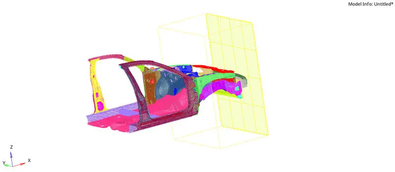
- Now, the rigid wall can be seen in graphical area as shown below.
ADDING MASS TO REACH TARGET WEIGHT 700KG WHILE CREATE CG ABOUT THE REQUIRED RANGE:
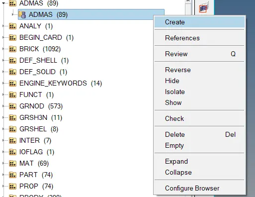
- Goto Solver > ADMAS >create as shown below.
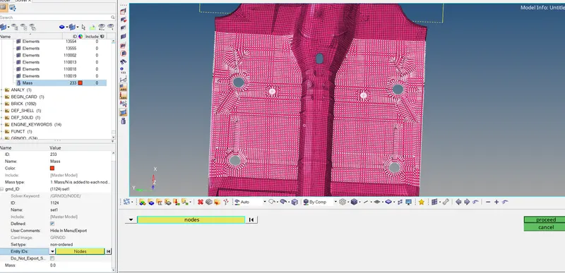
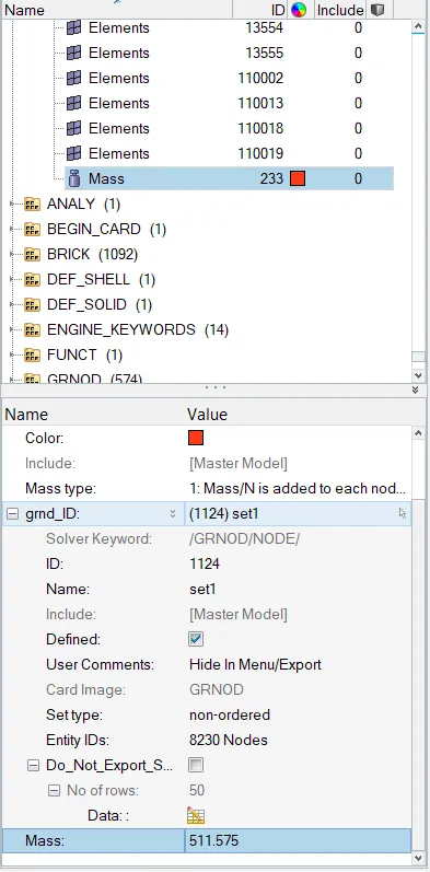
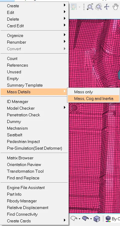
- Next check the total mass and centre of gravity.
- Goto menu bar select Tools>mass details>Mass, Cog and Inertia.
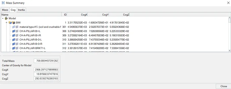
- Already mentioned in the condition the weight is 700kg see the above image total mass is 700kg.
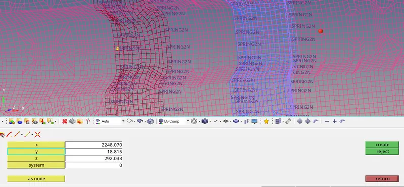
- Create the COG by using the above values to create a node as shown below.
GIVE THE INITIAL VELOCITY 35mph:
The initial velocity is 35 miles per hour(mph) convert into meter per second (m/s).
1mile=1609.34 meters.
1 hour=3600 seconds.
35mph=35×1609.34/3600 m/s.
=15.64 m/s.
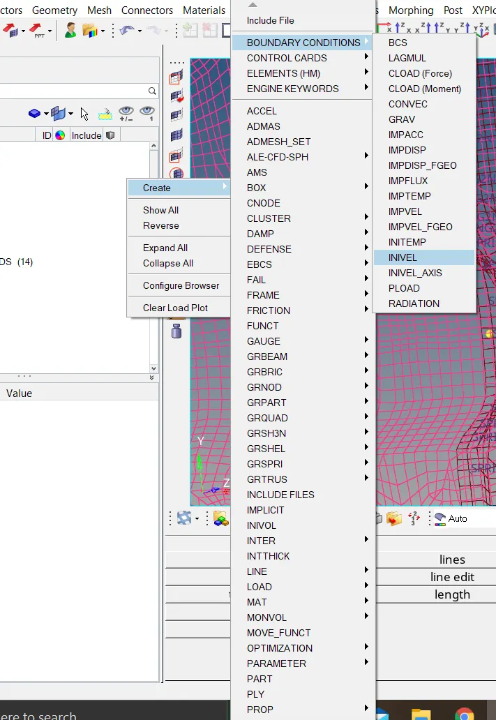
- Goto Solver Browser > Create >BOUNDARY CONDITIONS >INIVEL.
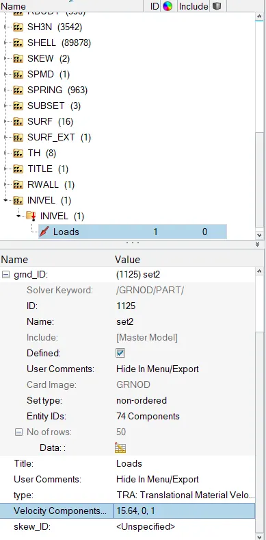
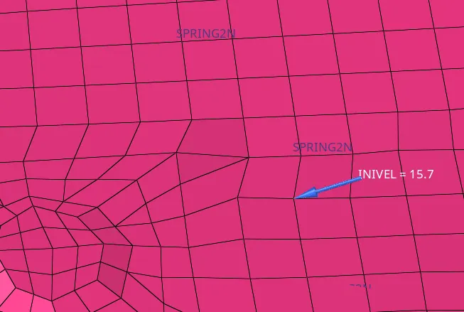
- The arrow indicates the Initial Velocity=15.64.
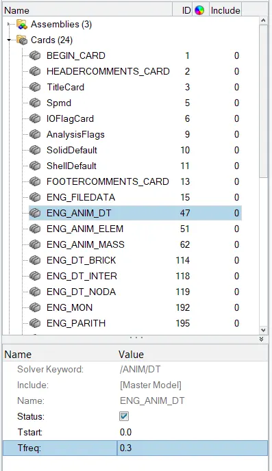
GIVE THE TIME STEP 0.3(Microseconds):
- Goto Model Browser > Cards > ANIM_DT as shown below.
RUN 80ms:-
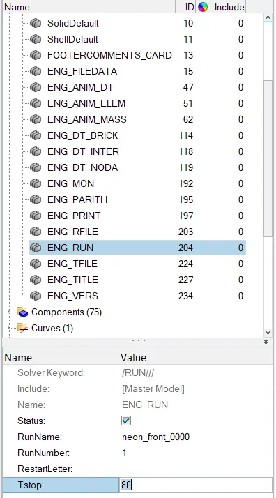
OUTPUT REQUESTS:-
1.CREATE SECTIONAL FORCES AT 174247 NODE:-
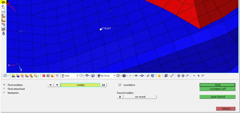
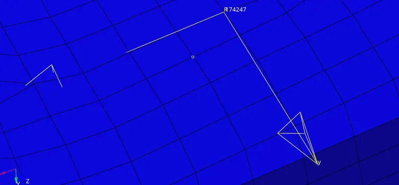
- First find the node by using the display number in the toolbar as shown below.
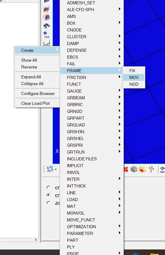
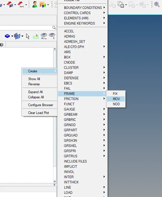
- Next create the frame open the solver browser right-click on the tab bar select Create>FRAME>MOV as shown below.
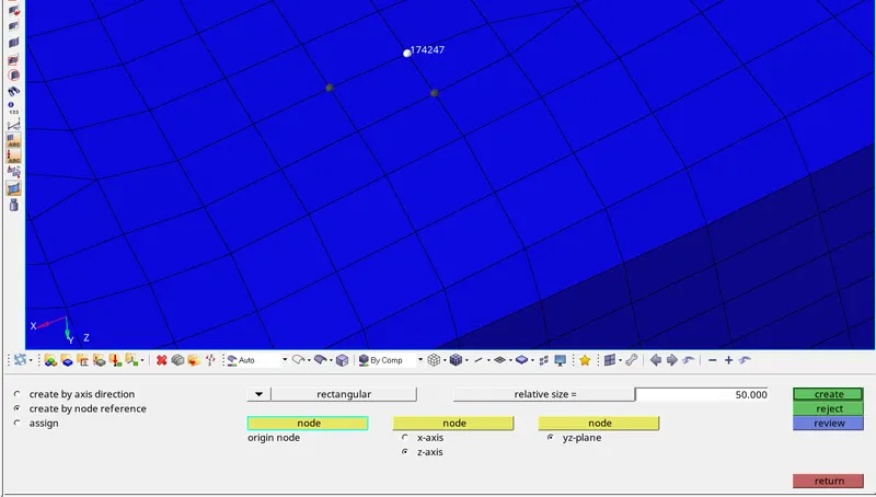
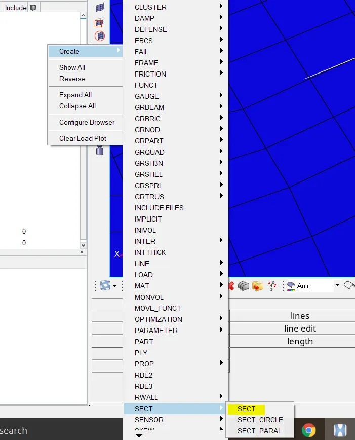
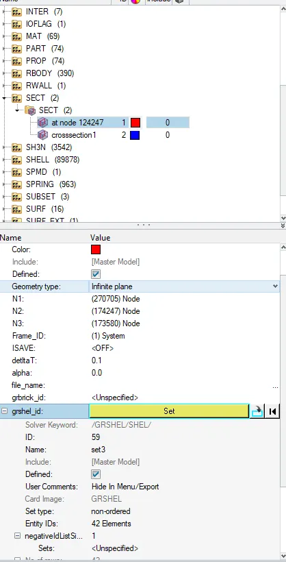
- Next create the section and add the above frame as shown below.
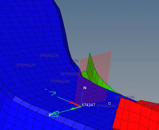
- The graphical section can be seen as below.
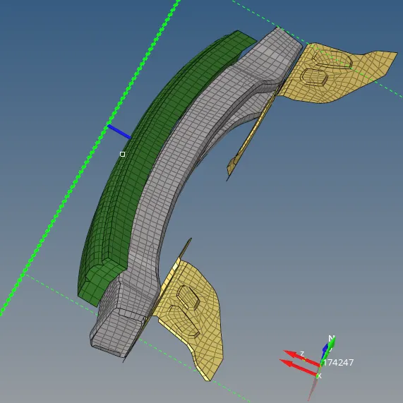
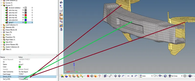
2.Axial force received on the rails from the bumper.
- Create the Type7 Interface for Bumper
3.Creating the cross-sections:
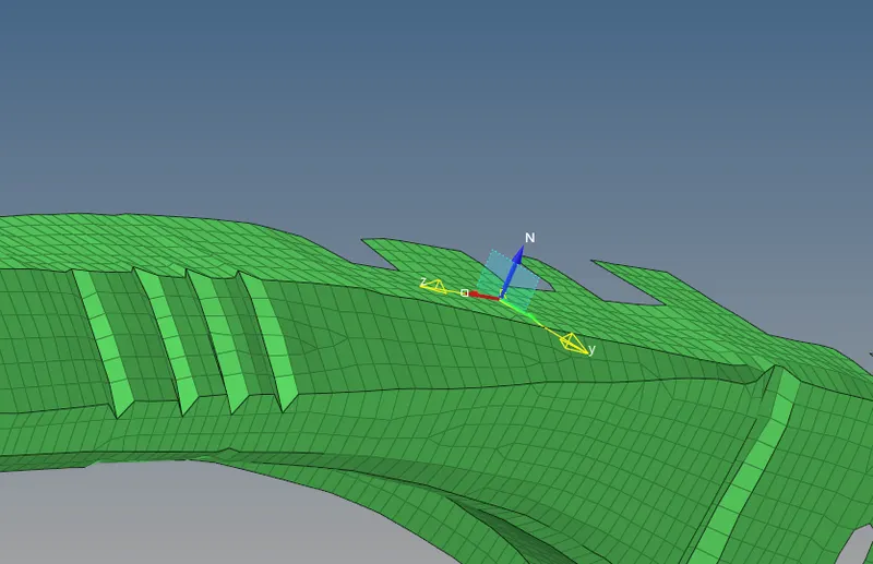
- Create a new frame on the bumper as shown below.
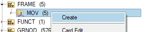
- Click on the create the frame will be visible as shown below.

- Next create the section and add a frame as shown below.
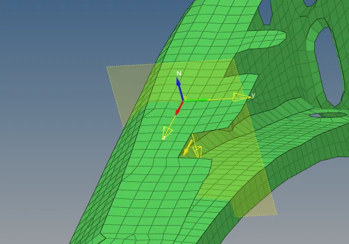
- Repeat the above steps and create a section at the left shotgun as shown below.
4.Create Cross sectional Forces on the pillar:
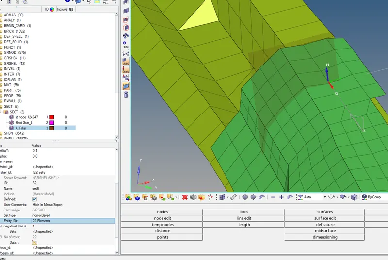
- First create the frame on A_piller as shown below.
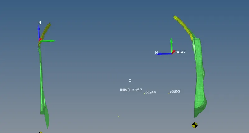
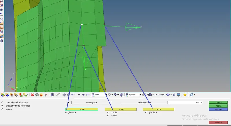
- Create the section and add the A_pillar frame.
- Goto solver browser right-click on the SECT click on the create give the required nodes, frame and elements as shown below.
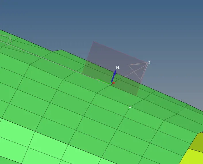
- Create the same on the Pillar_B.
5.CREATE THE ACCELEROMETER AT THE BASE OF B_PILLAR:
- Goto solver browser right-click on the tab bar select create click on the ACCEL as shown below.
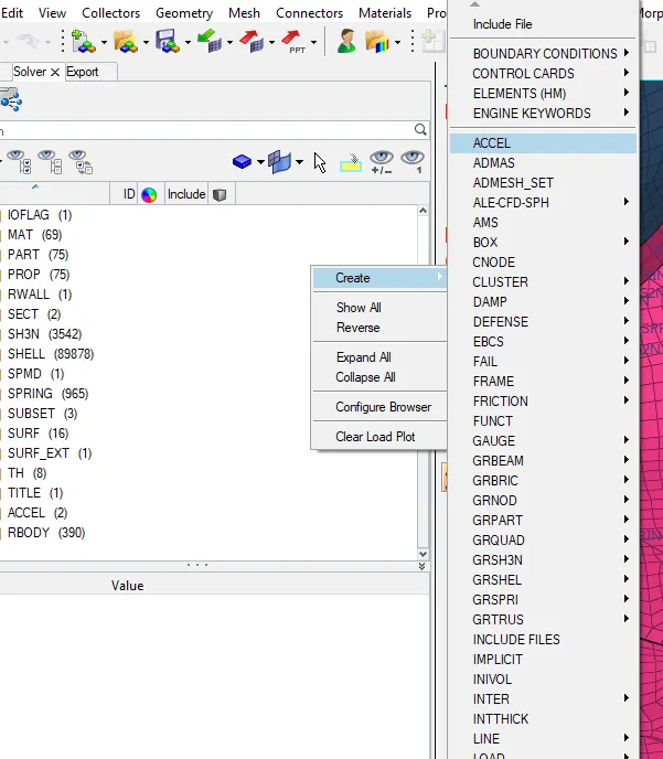
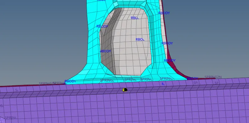
- Click on proceed the accelerometer is visible as shown below.
- Repeat the above step create an accelerometer at the right B_pillar as shown below.
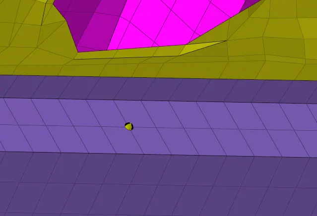
6.CREATE INTRUSIONS AT NODES 66695,66244:-
- Create springs at nodes 66695 and 66244.
- First display the nodes by using display number.
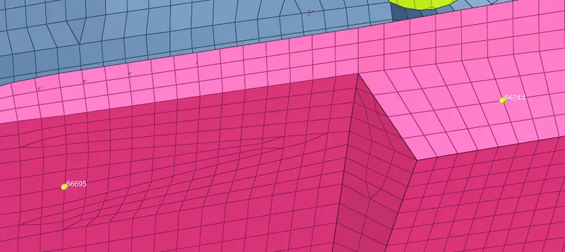
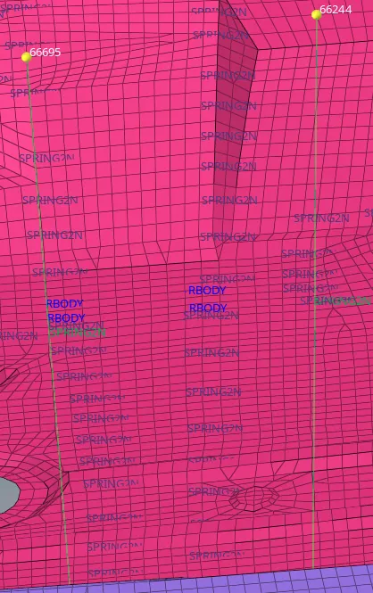
- Create properties for springs and assign them.
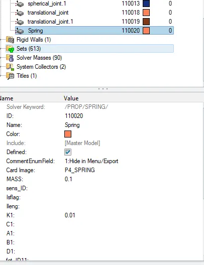
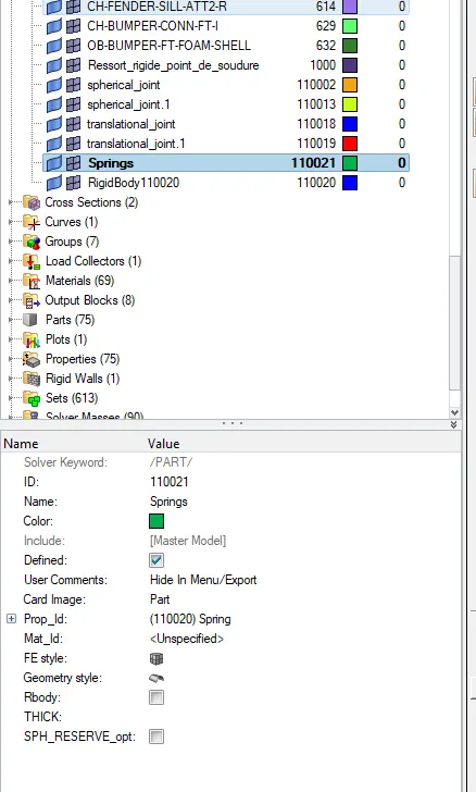
- Now export the model in radioss file as shown below.
RUNNING MODEL CHECKER BY USING HYPER CRASH:
- First go to the menu bar select Applications >Hyper Crash as shown below.
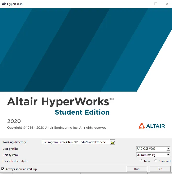
- Next import the modified radioss stater file on Hypercrash as shown below.
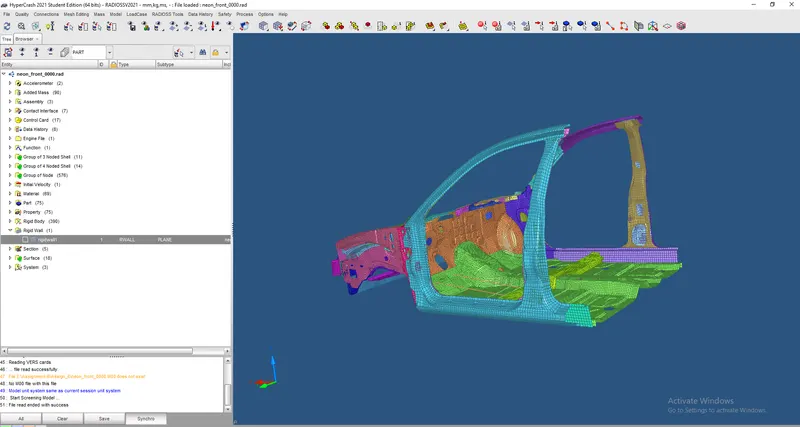
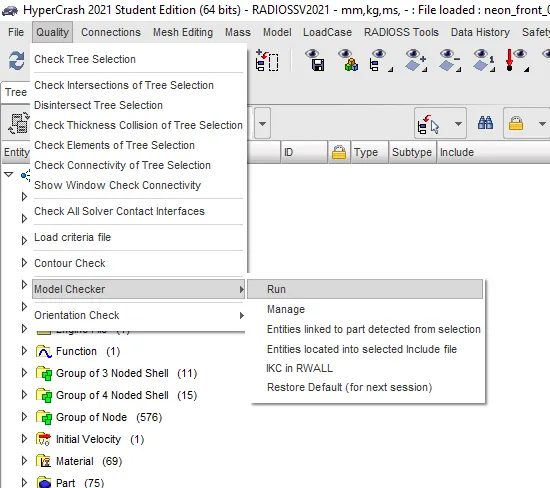
- Goto menu bar select Quality> Model Checker> Run.
SIMULATION:
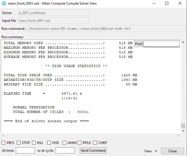
- After completing the model checker Goto > Hypermesh >Analysis > Radioss , let's run the simulation.

- Click on the radioss the simulation is run as shown below.
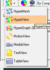
- Goto Hyperview.
- Select the h3d animation file and click on the apply as shown below.

- The animation is visible in the graphical area as shown below.
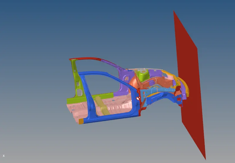
- Goto animation click start to see the graphical area the car frontal is striking the rigid wall see below.
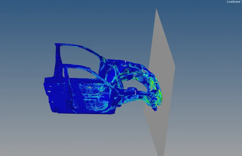
Von Mises:The above animations show deformation taking place in the frontal area and passing the car's rear end. I am observing the animation the driver and passenger seats are safe. The car frontal area is damaged. The deformation is based on the COG of the car so place in the correct position gives the best result.
Plastic strain:The plastic strain means that the element has deformed and absorbed the forces. The plastic strain develops in front of the car & doesn't goes to the rear-end of car it shows a good sign.
Plotting the Graphs:
Energies graphs:
- Click on the Global variables >Internal energy>kinetic energy>Contact energy>Hourglass energy>Total energy >MAG>Apply.
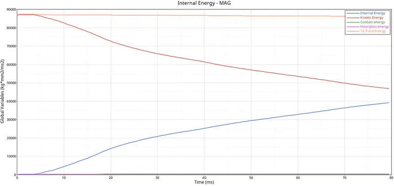
- In the above image, the hourglass energy and total energy is constant so the simulation is stable.
- Internal energy is increased at 80ms and kinetic energy is decreased at 80ms.
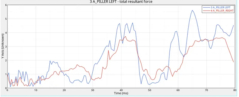
A_piller cross-sections:
Shot_Gun cross-sections:
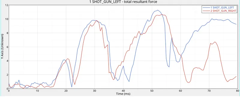
Rails Cross-sections:
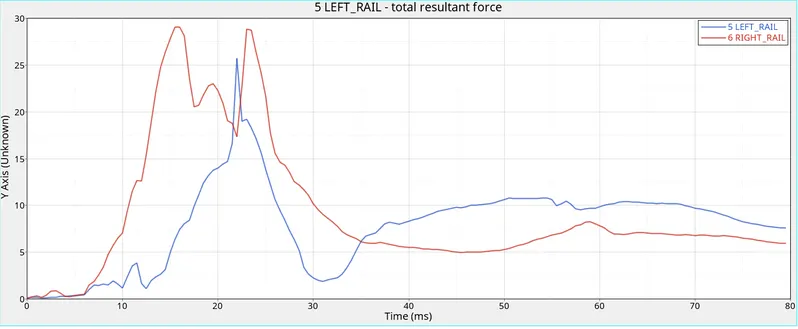
Axial force received on the rails from the bumper:
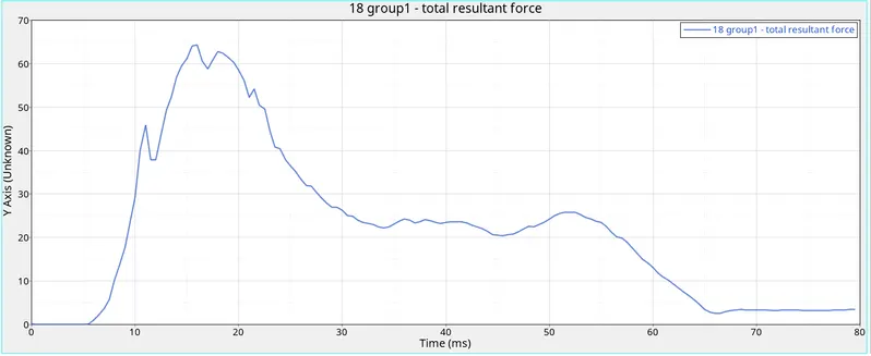
Rigid wall:
B_Piller accelerometer:
Intrusions:
CONCLUSION:
Thus the Frontal crash simulation with prescribed inputs has been performed and simulated outputs have been observed & submitted.