Week-6 Calculate the Stretch Ratio by comparing the ELFORM (-2,-1,1,2) with Ogden_Material Model.
Aim:To calculate the stretch ratio by calculating the ELFORM(-2,-1,1,2) with Ogden Material Model.
Objective:
Case setup for Ogden material and behaviour has to be studied during changes in the ELFORM(Element Formulation).
Procedure:
1.Import the given ogden material keyword file into the LS-PrePost.
2.Open the Material card in the keyword manager to see the ogden material card as below.
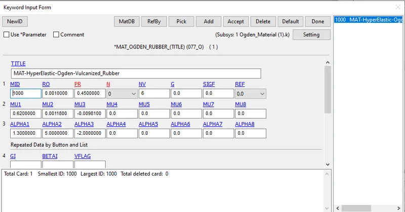
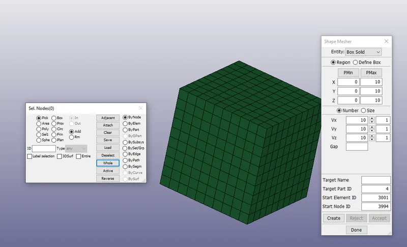
3.Create a box solid using Element and mesh> Shape Mesher > Box Solid. Dimensions of the box are 10mmm*10mm*10mm.
4.Making 10 elements in all directions the box solid will be created as below.
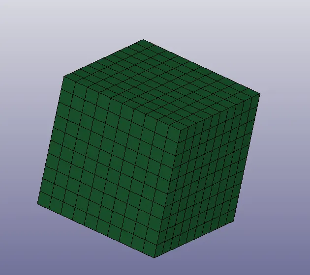
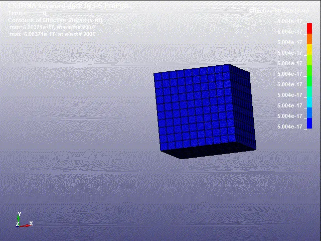
5.The box solid will be displayed in the Graphical interface as below.
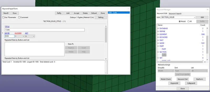
6.Goto the solid card under the section in the keyword manager and set the element formulation to 1 as we need to check for -1,1,-2,2.We will be changing the ELFORM and observe the case results.
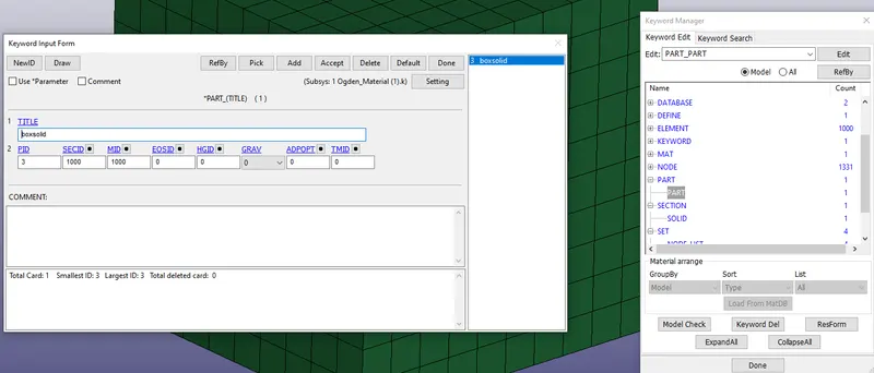
7.Goto part under the Part in the keyword manager and assign the PartID,sectionID and MaterialID.
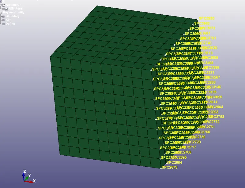
8.Create the Spc set under the boundary conditions in the keyword manager and select the nodes as shown in the below direction to fix them and allow the constraints as below.
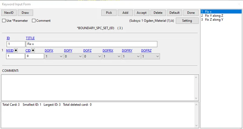
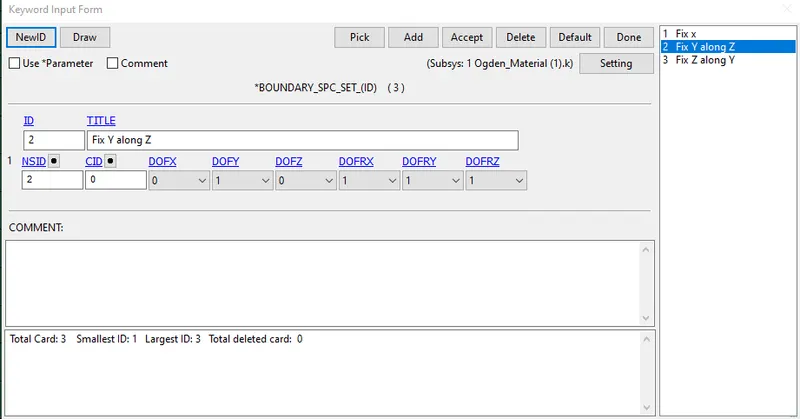
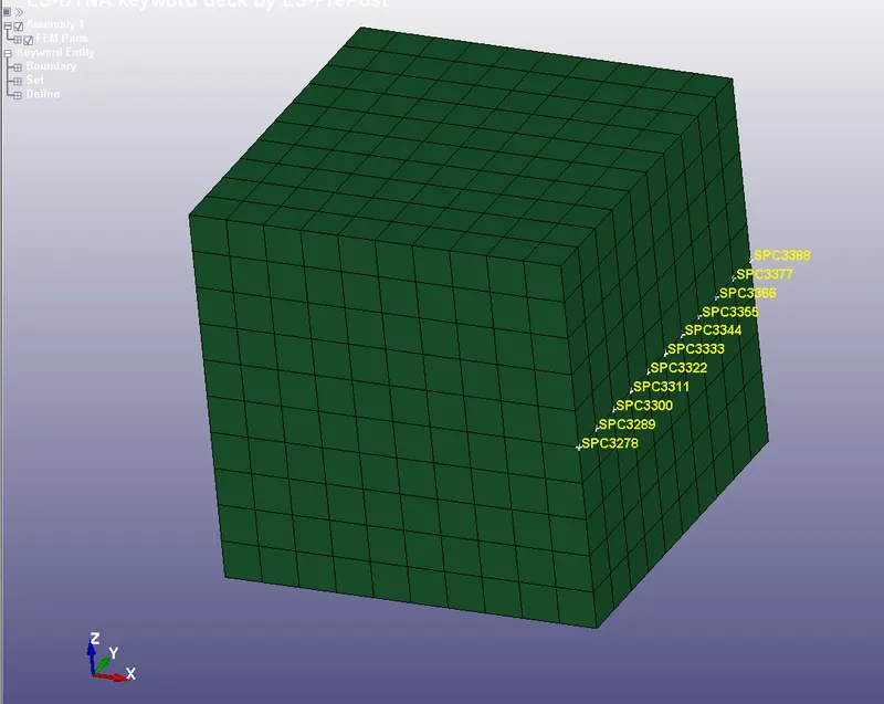
9.Similarly create the another ID and select the nodes as below and set the constraints as below, this set is to fix Y along Z.
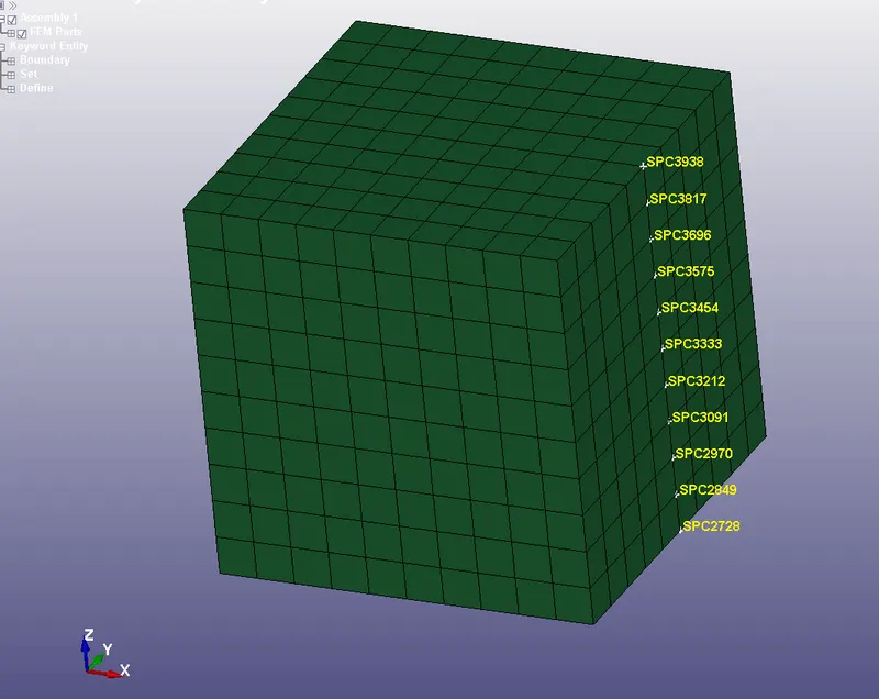
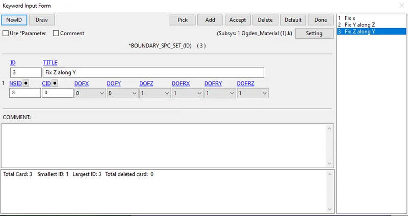
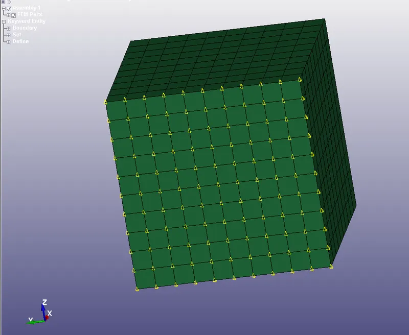
10.Create another set and select the nodes and constrain them such that it ius fixed in Z along Y.
11.Now create the Prescribed motion set under the boundary conditions and select the nodes opposite to the spc set as below. And set the displacement card for the nodes of the box solid.
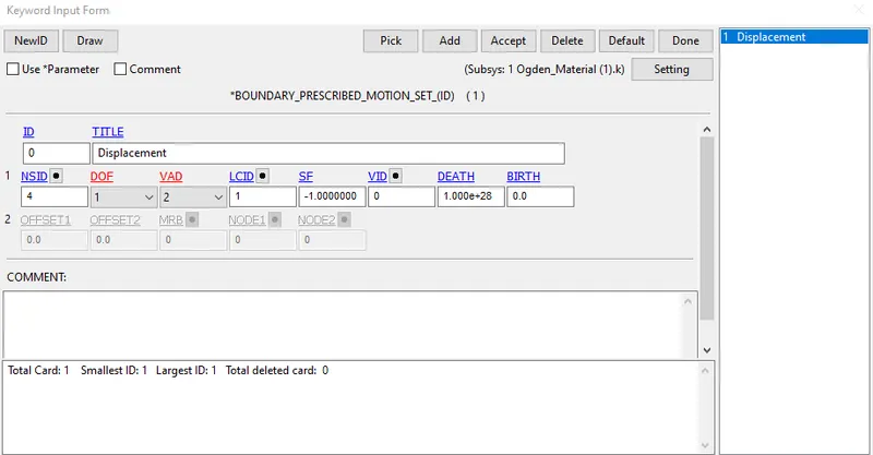
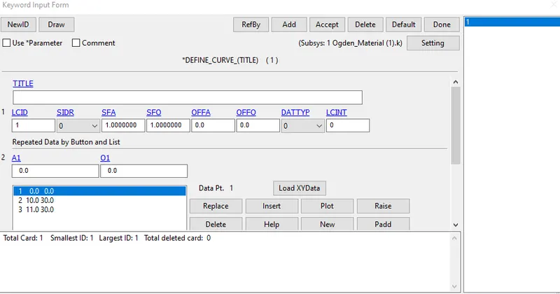
12.Define curve as shown below in the keyword manager and insert trhe values as shown below.
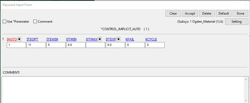
13.Create an Implicit Auto under the Control card in the keyword manager.
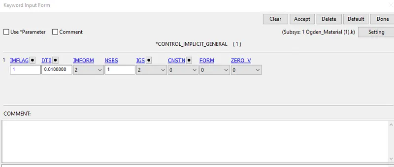
14.Create the Implicit General card under the control tab in the keyword manager as below.
15.Create the implicit solution under the control tab in the keyword manager as follows.
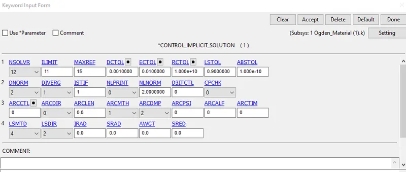
16.Create the implicit solution under the control with following values as below.
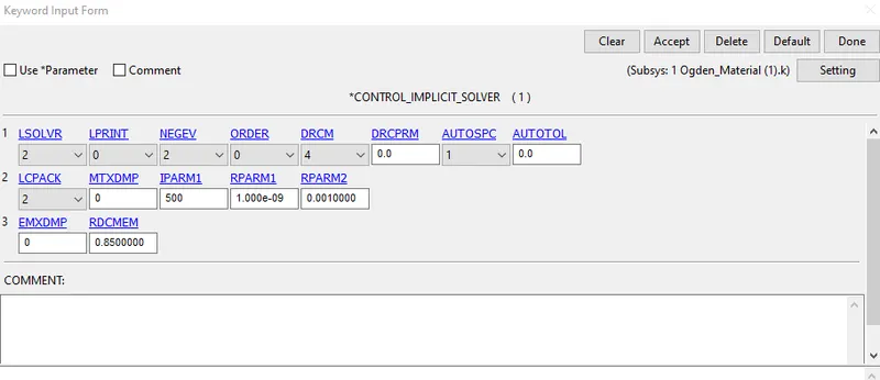
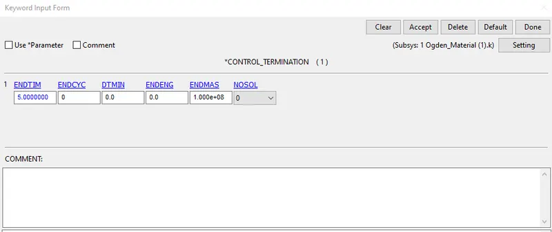
17. Create the termination card to end the simulation for a period of time. It is created under the control tab in the keyword manager.
18.Create the binary plot under the database tab.
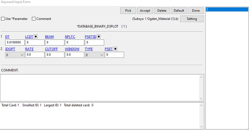
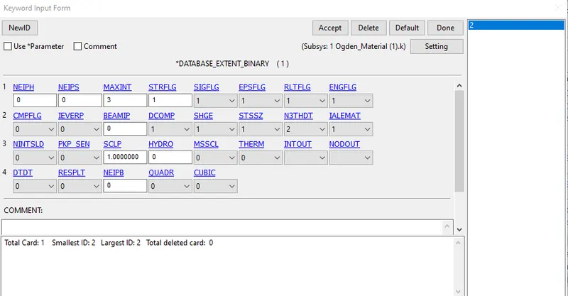
19.Also create the Binary Extent under the database in the keyword manager.
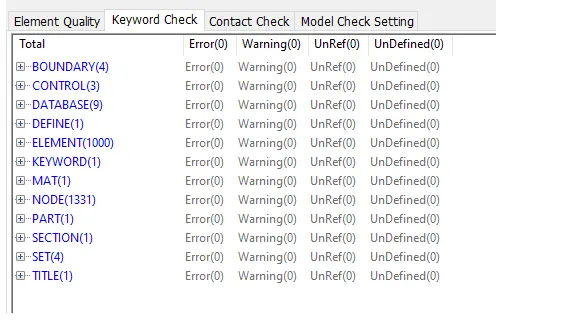
20.Go to the model checkerto check the errors and warnings for the simulation to run.
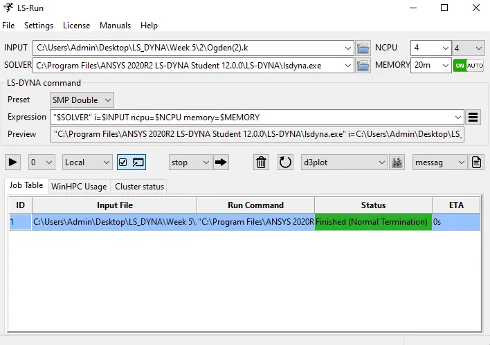
21.Save the keyword file and insert the file in the LS Run to the simulation, the progress can be seen as below.
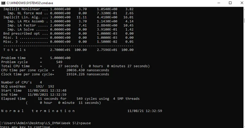
22. The termination is completed and the status is normal termination, the files are saved in the target folder.
CASE-1(ELFORM 1):
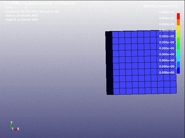
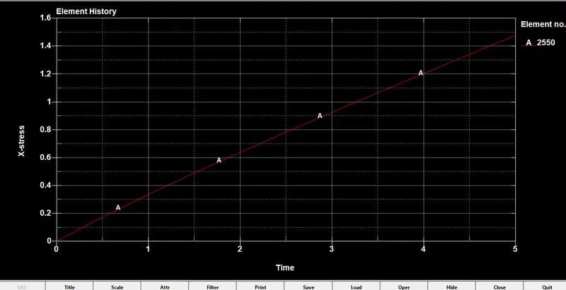
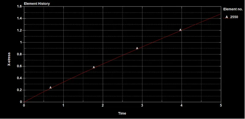
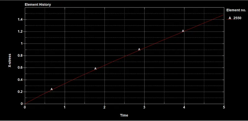
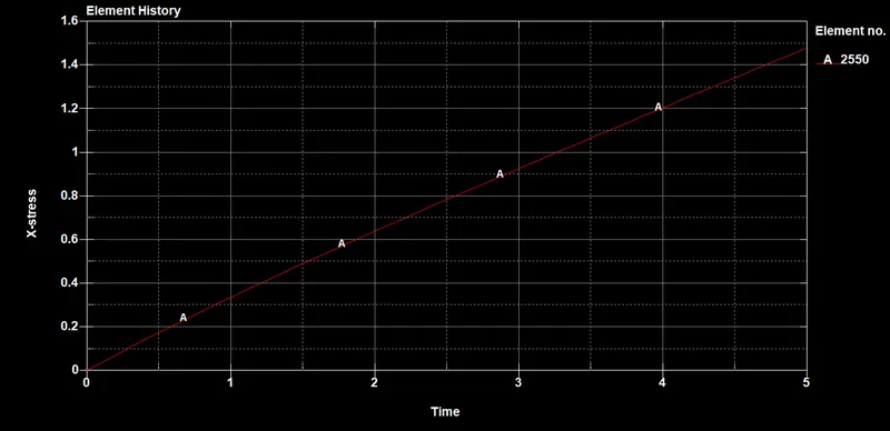
Stress Graph for an element:
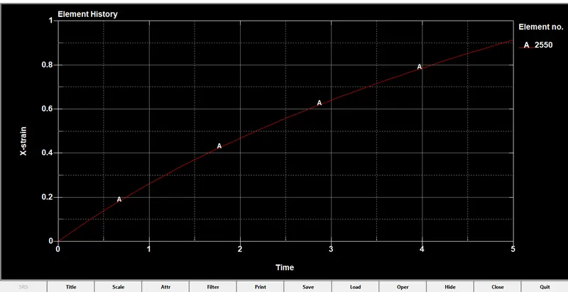
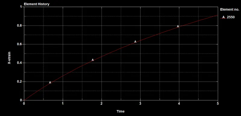
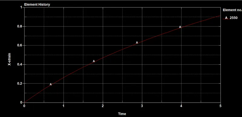
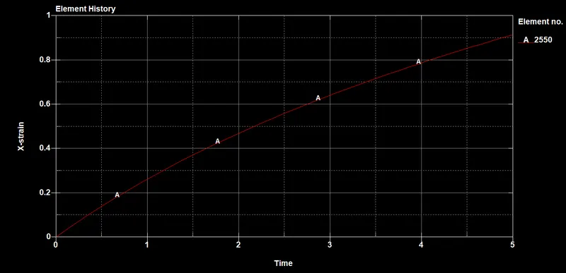
Strain graph for the element:
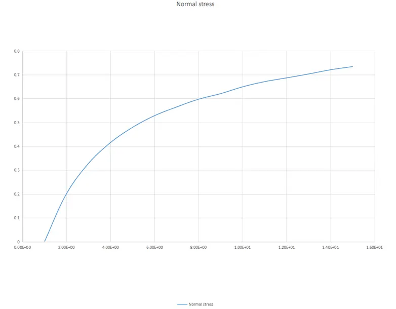
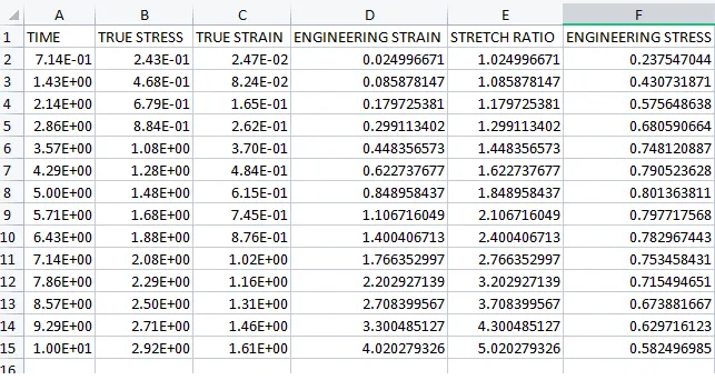
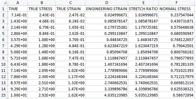
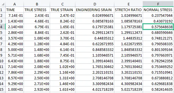
The below fromulas are used to find the normal stress.
Engineering stress or Normal Stress (σe)= True Stress(σt)/Stretch Ratio(λ).
Engineering Strain(ε)=EXP(True Strain)-1.
Note:Take the true stress and strain values of above graphs.
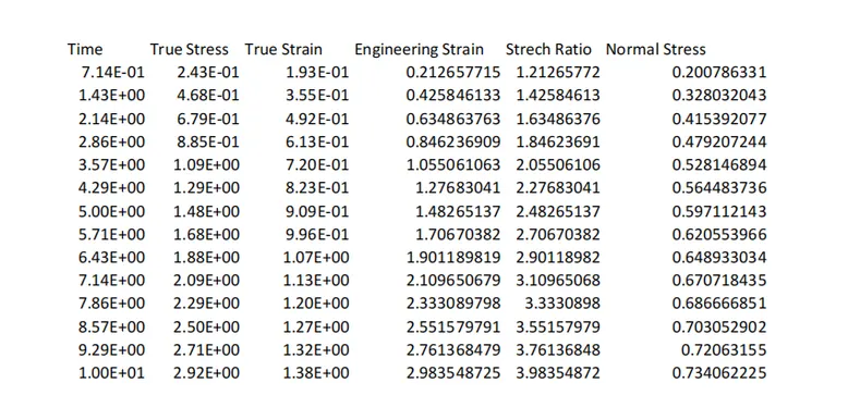
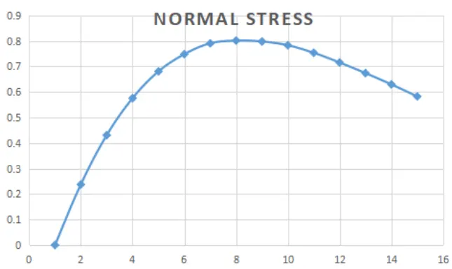
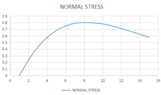
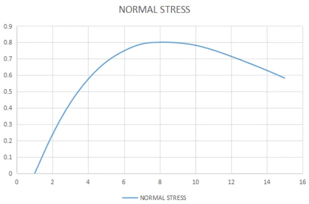
- Take the normal stress and stretch ratio to plot the graph.
CASE-2(ELFORM 1 to 2):
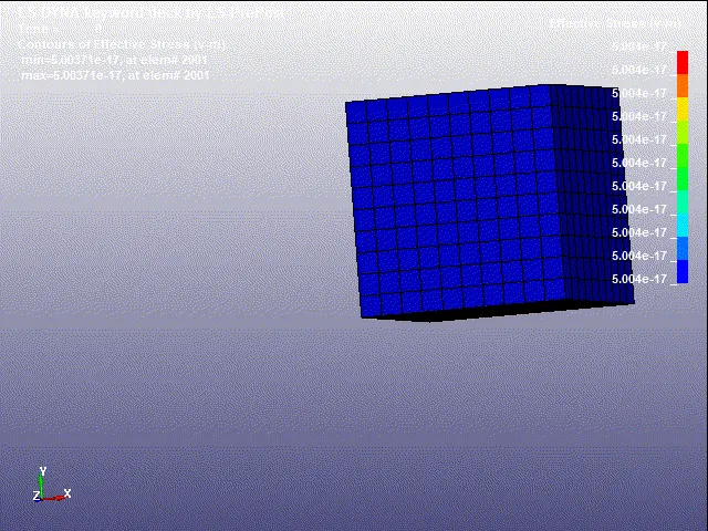
Case-3 ELForm(2 to -1):
CASE-4 (ELFORM -1 to -2):
Conclusion:
As the Element formulation (ELFORM) changes the normal stress changes. Here the variation for the cases is as below,
CASE-1(ELFORM 1): Normal stress increased gradually.
CASE-2(ELFORM 1 to 2):Normal stress is decreased by the end of the simulation.
CASE-3(ELFORM 2 to -1):Normal stress is decreased.
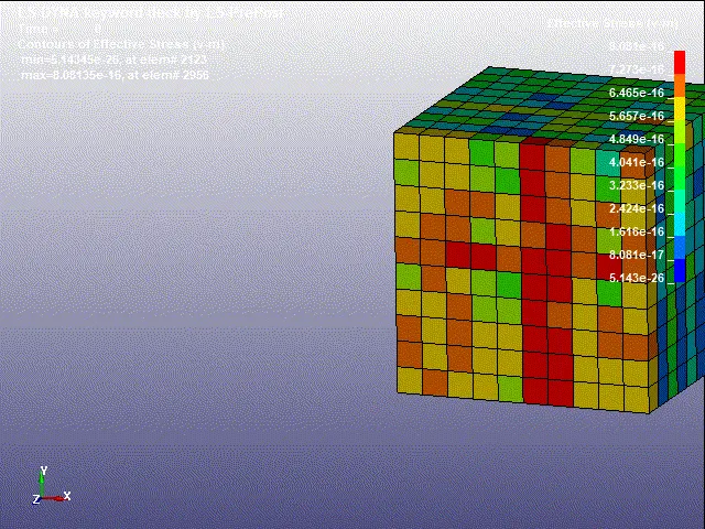
CASE-4(ELFORM -1 to -2): Normal stress is decreased by the end of the simulation.