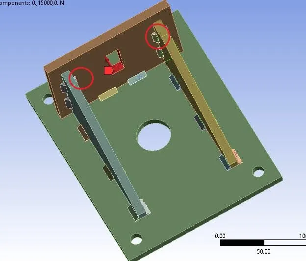
Week 3 Verification of Weld Joints
Aim: To perform Analysis on weld joints and comeout withe the best possible output.
Objectives:
- To apply different materials with prescribed parameters
- Analyze different factors.
- Verify the stress factor.
- Compare all the 3 cases.
Procedure:
Import the model into tyhe Mechanical module.
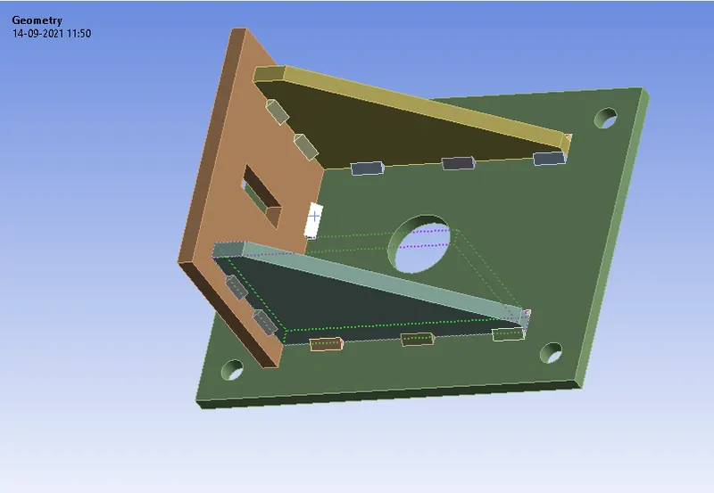
- Click on geometry tree and rename the other components based on thire structure.
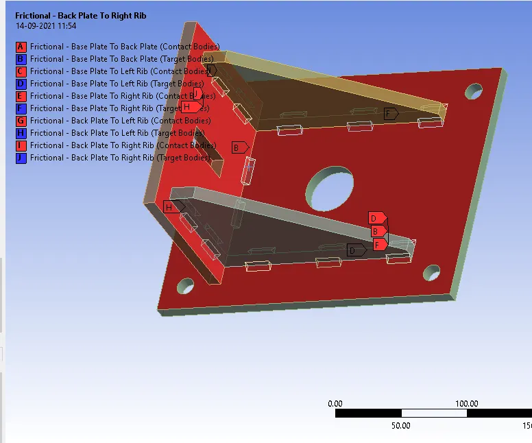
- Click on contacts and select rename based on definition.
- Change the contacts other than welding joints and change their type to frictional and give the frictional coefficient as 0.3
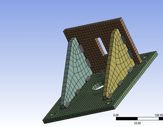
- Mesh the given specimen with a sizing of 7mm selecting the both plates.Click on generate mesh.
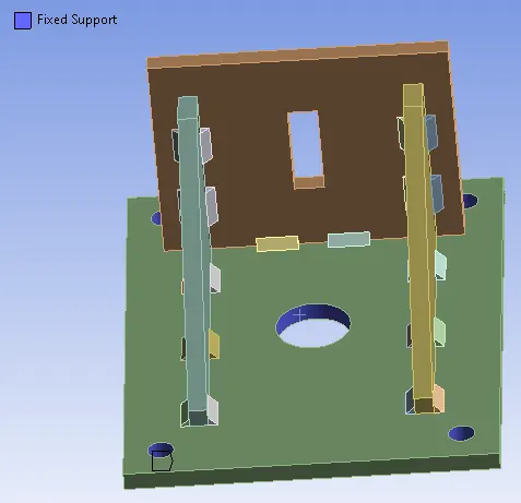
- Create the support as fixed and select the geometry as the holes on the base plate.
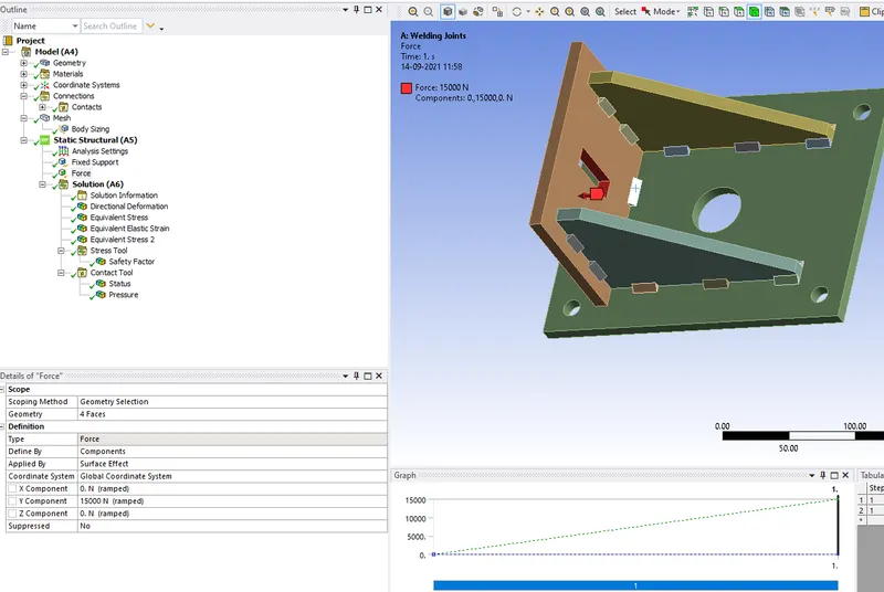
Create the force on the rectangular hole and define it by component with a magnitude of 15000N.
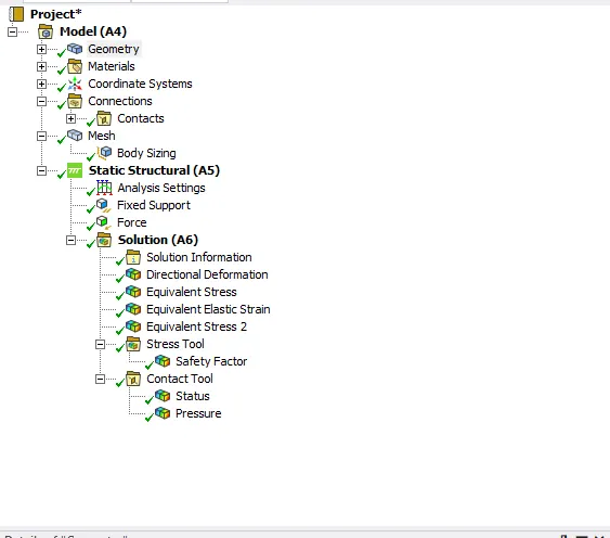
Insert thye Parameters in the solution Directional deformation in Y axis, Equivalent Stress(Select weld joint geomtries),Equivalent Strain, Safety factor,Contact Tool(Only Frictional joints).
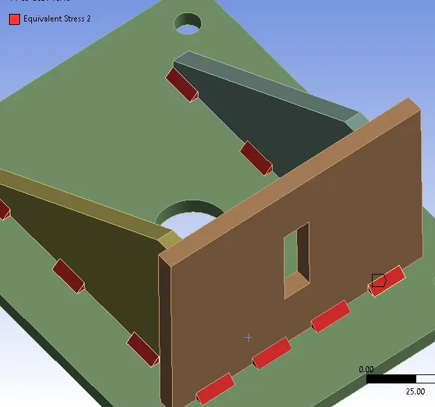
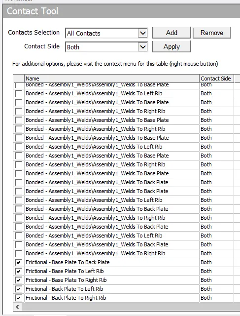
These all are the parameters we are looking for,
CASE-1 Stainless Steel:
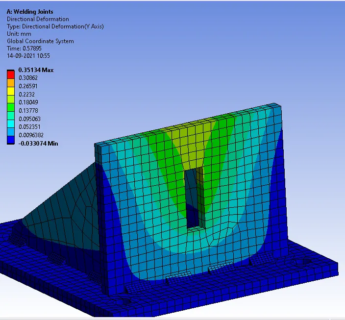
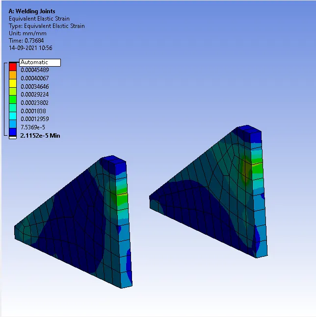
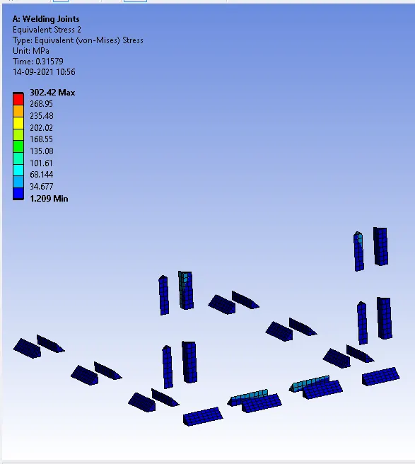
Assign stainless stell for all the geometries.
Directional Deformation:
Equivalent Strain:
Equivalent Stress for Weld Joints:
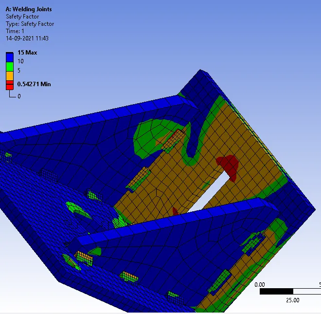
Safety Factor:
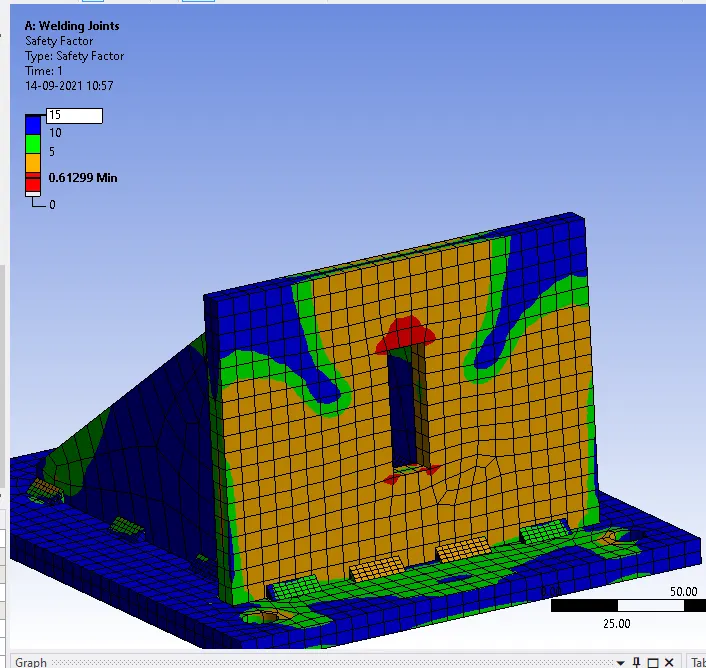
CASE-2(Aluminium Alloy):
Directional Deformation:
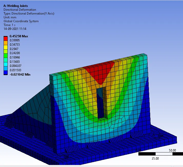
Equivalent Strain:
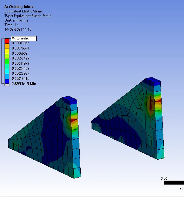
Equivalent Stress for Weld joints:
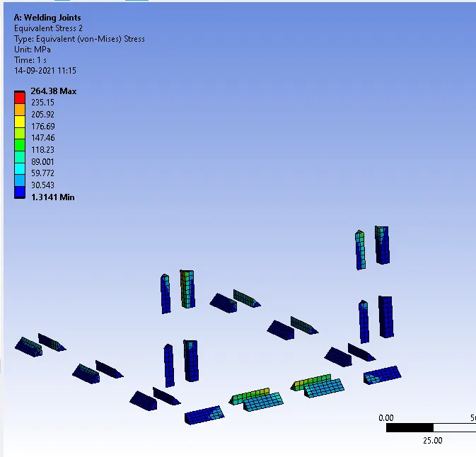
Safety Factor:
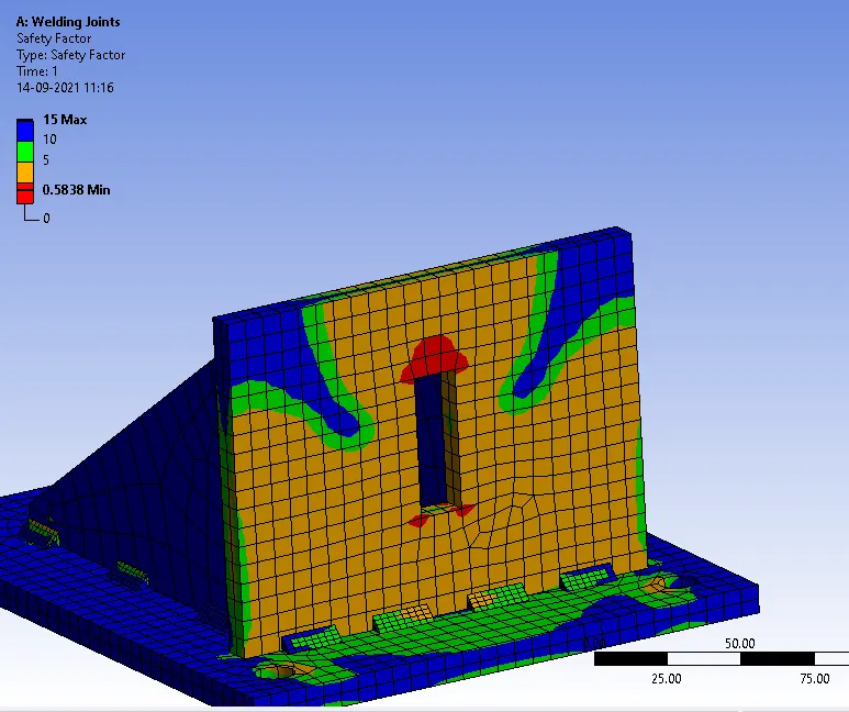
CASE-3 (Bronze):
Total Deformation:
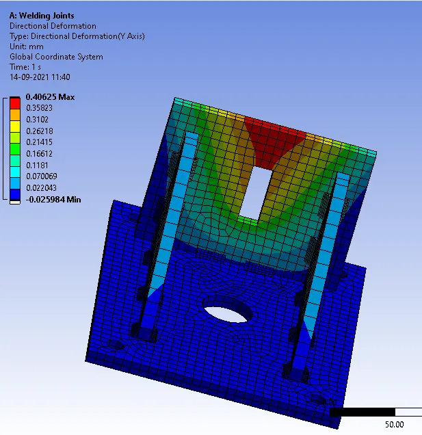
Equivalent Strain:
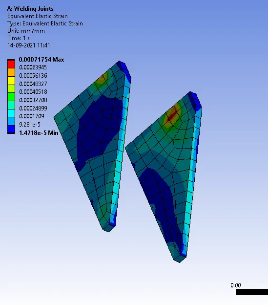
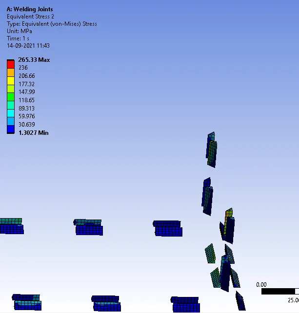
Equivalent Stress for Weld Joints:
Safety Factor:
Comparison:
| Materials | Directional Deformation-Y (mm) | Eq. Stress at Weld (Mpa) | Eq. Strain |
| Stainless Steel | Max:0.35134 | Max:302.42 | Max:0.000659 |
| Aluminium Alloy | Max:0.4525 | Max:264.38 | Max:0.000923 |
| Bronze,Cast |
Max: 0.40625 |
Max:265.33 | Max:0.000717 |
Here in all the cases these 2 weld joints experienced the maximum stress compared to the other.