Assignment 3-2D Element Formulation Challenge
#3 Assignment Crashworthiness Analysis using Hypermesh and Radioss
AIM:
1. Run the simulation with default property cards
2. Run the simulation with changed values in the property card
3. Compare both the cases
Hourglass:
Hourglass is the deformation that is noticed in the deformation of elements due to applied load.But the strain energy due to deformation is not recorded for that element. It is also known as Zero Deformation modes, where an element is seen deformed.
It is usuallyt seen in post-processing stage where elements can be seen in zig-zag formation.
After Hourglass Effect
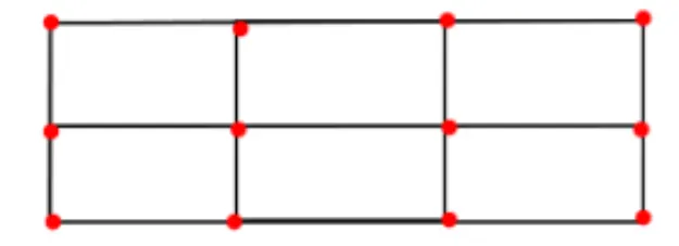
After Hourglass Effect
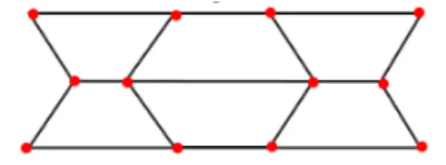
METHODS TO CONTROL THE HOURGLASS:--
1. Perturbation method(viscous method)
2. Physical stabilization method (stiffness method)
Perturbation method(Viscous method):-
- This method is generally used for the elements with Ishell: 1,2,3,4 or Q4 elements.
- The process how this method work is: When the hourglass deformation occurs---> There will be some damping applied,
which is stabilizes the deformation, which results in controlling the speed of deformation. - But this damping opposes only the velocity, But not the force. So, the force is introduced, which results in adding some
stiffness to the elements. This stiffness helps in controlling the hourglass. - The force is applied externally, by some other means. But not from FEA nature. This force constitutes energy called
"Hourglass energy", Which is artificial energy(neither Kinetic nor internal energies). It is a loss of both energy types. - If the hourglass energy is added along with the kinetic energy & Internal energy, A balance system is obtained.
- Recommended for high velocity or high strain rate problems. Example: Involving high explosives.
- A huge amount of hourglass energy is generated.
Physical stabilization method (stiffness method):-
- In this method, the stiffness is getting added right from the material level. This will have a large effect on our component.
- It is recommended for fewer velocity problems.
- used for QEPH elements.
- Less amount of hourglass energy is needed. Because it is going to be controlled before it arises.
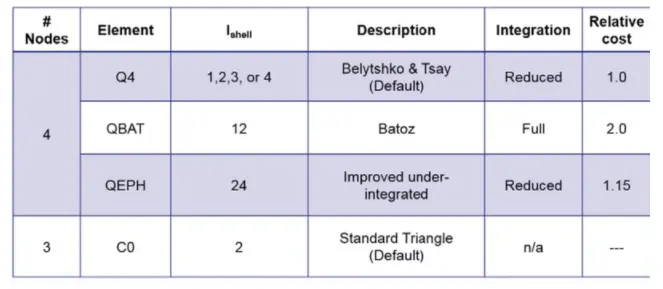
Q4 element:
- It is an under(or) reduced-integrated element. Because it has only 1 integration point for an element.
- It is represented in the radioss solver by an entity named "Ishell(1,2,3,4)".
- Usually Ishell:1, Ishell:4 elements are used, when no more velocities are to be found.
- By default, the solver takes as Ishell:1.
- As it has only 1 integration point, the time required to solve the problem with this type of element is relatively less.
- The cost required to solve this type of element is relatively low.
- But there will be no accuracy in the results.
QBAT element:
- It is a fully integrated element, Which means it comprises 4 integrated points. Each point is near to each node.
- It is represented in the radioss solver by an entity named "Ishell: 12".
- Because of these 4 Gaussian integration points, there will be no Hourglass deformation.
- Using this element is not economical. But the achieved results are more accurate than the remaining Ishell elements of
quads.
QEPH element:
- It is an improved under-integrated element with physical hourglass stabilization within itself.
- It is represented in the radioss solver by an entity named "Ishell:24".
- This type of element is mostly used recently. Because of its best compromise between the cost, quality& accuracy in results
- It is widely used in the automotive industry.
CO element:
- It is a standard co-rotational triangle, with modification for large rotations.
- Usually, it helps in representing the tria elements with the entity named "Ish3n:2".
- It consists of 1 integration point.
- No hourglass deformation.
- Low CPU cost.
- Results may not be accurate.
Procedure :
Import the file
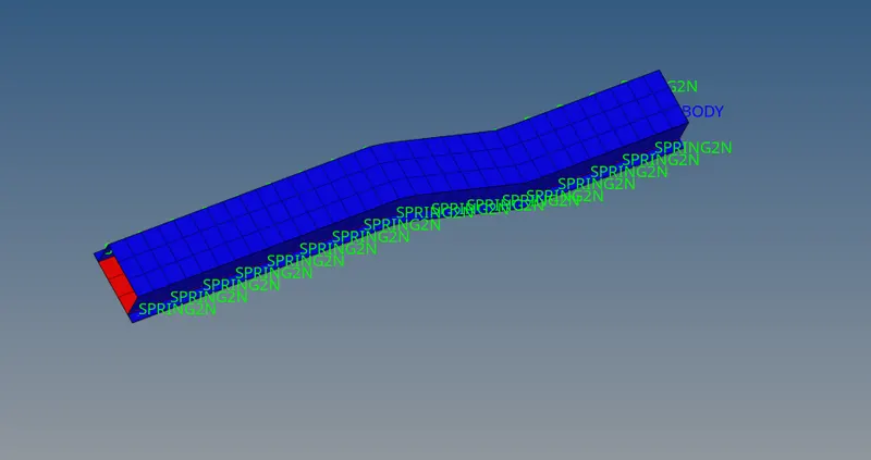
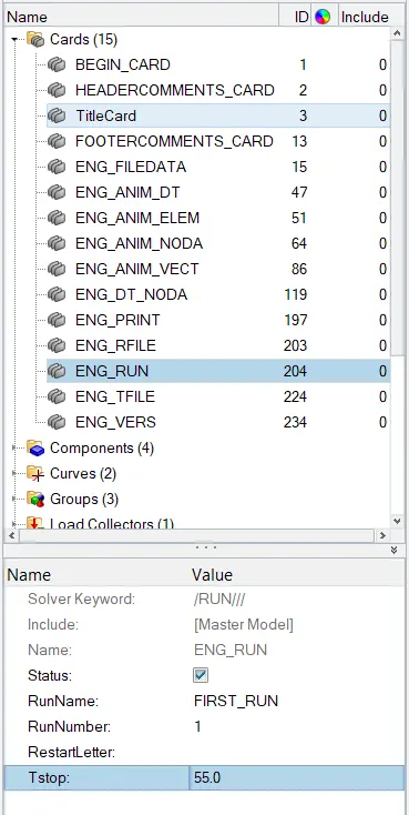
Change the Eng Run to 55.0
Change the Anim / DT as the following
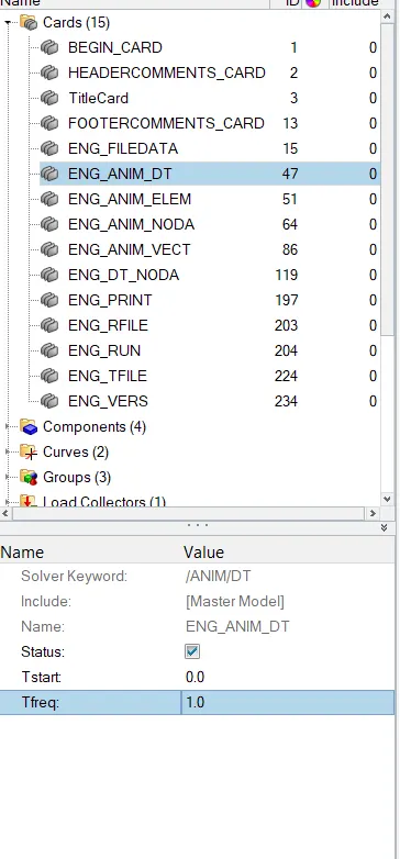
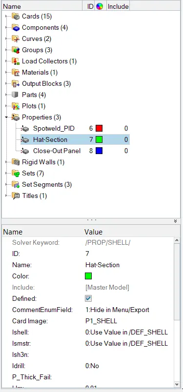
Leave the default values in the first case
Goto Analysis tab

Tick the include connectors in the options type as -nt 4

Click on Radioss and the pop-up will be as shown.
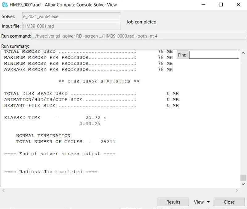
Click on the results then the Hyperview Tab will open as follows,

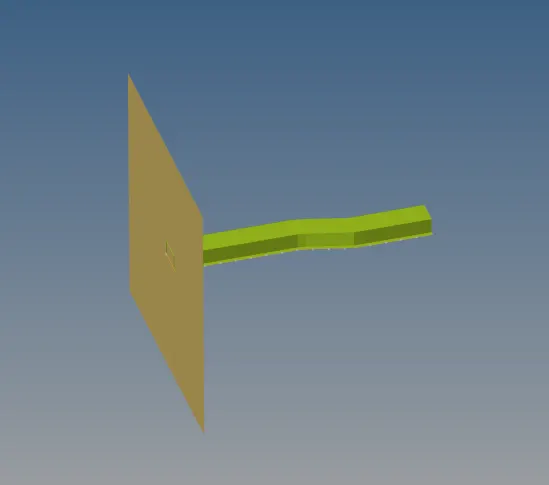
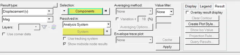
Click on Contour option you will see the display tab as follows,
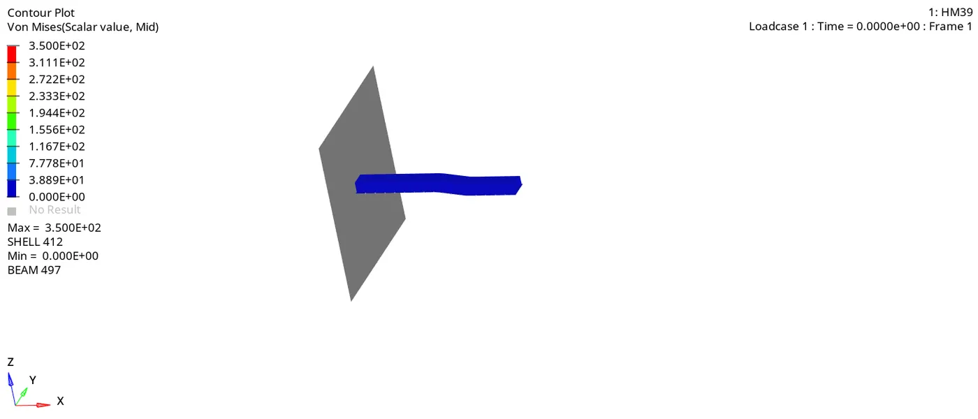
Change the result type as Von Misses then the element failure can be seen as followed,
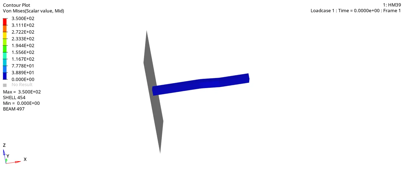
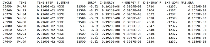
Open the 0001.Out file that is created in the target folder.
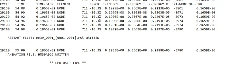
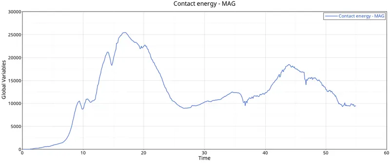
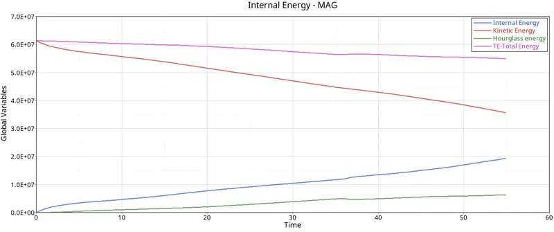
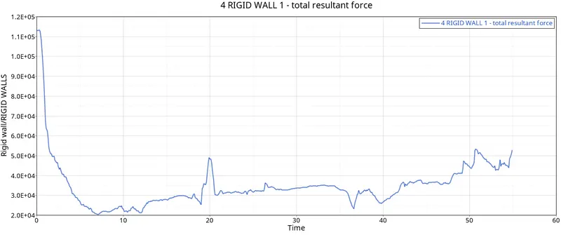
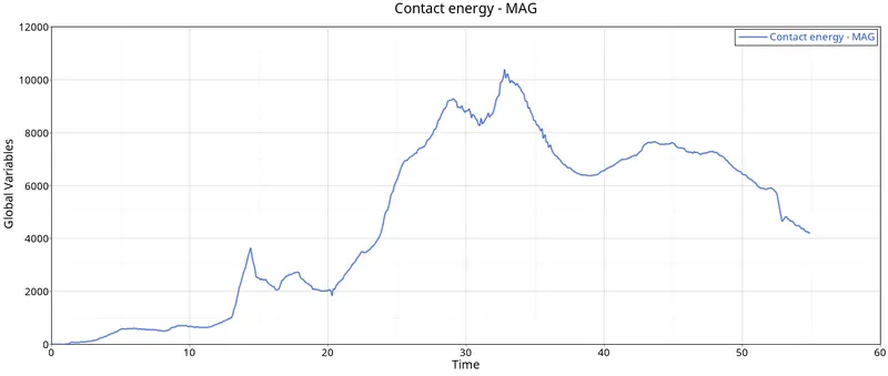
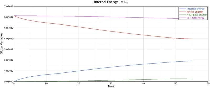
Now open the Hypergraph 2D and insert the T01 file and plot the graph for the given parameters

CASE-2
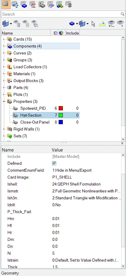
Recommended properties:
| Parameters | Comment | |
|
Ishell =24 |
QEPH 4 nodes shells are best combination of cost and accuracy. | |
|
Ismstr=2 |
Full geometric nonlinearities (default)with possible small strain formulation activation in RADIOSS Engine. | |
|
Ish3n=2 |
Standard 3 noded shell (C0)with modification for large rotation(default) |
|
| N=5 | Number of integration points set to 5 for accuracy bending. | |
|
Ithick=1 |
Thickness change is taken into account for accuracy. |
|
|
Iplas=1 |
Iterative plasticity for good accuracy. |
Change the property card as per recommended values
Change the view to contour and you will see the deformation.
Values in the 0001. Out file
Plot the graph
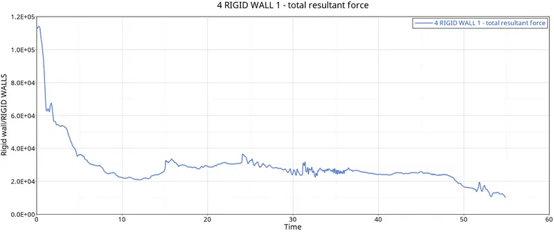
Comparitive observations Case-1 Case-2
Obtained Maximum Kinetic Energy 0.3563E+08 0.4376E+08
Obtained Maximum Internal Energy 0.1932E+08 0.1750E+08
Obtained Maximum Energy Error -10.3% -0.1%
Hourglass Energy Varying Constant
Requirement of Hourglass Energy Requires Energy Balance Not required Energy balance
Results Results are less accurate Result is accurate
Conclusion:
Learned running simulatioin
Learnt changing properties in cards
Learnt Hypergraph creation