Week - 4 - Crash Box Simulation
Aim: To perform a simulation of a crash box with rectangular channel striking a rigid wall.
Objective:
- To assign the values and other criteria to the crash box to perform the simulation.
- To perform the simulation and plot graphs for the energies generated during the simulation.
- Attach the prerequisite files.
Procedure:
1.Import the crashbox keyword file into the LS-Dyna as shown in the below graphical interface.

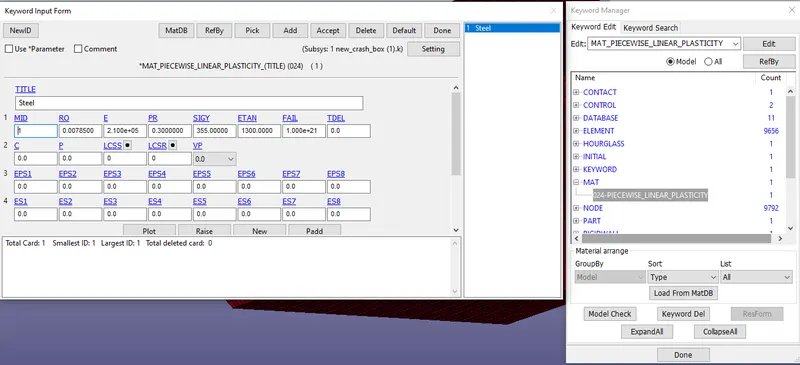
2.Create a material of type 024 Piecewise Linear Plasticity, name it as steel and assign the values to the material.
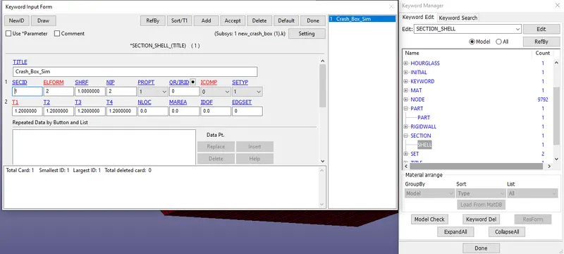
3.Create a section shell in the keyword manager and assign the thickness to the crashbox.
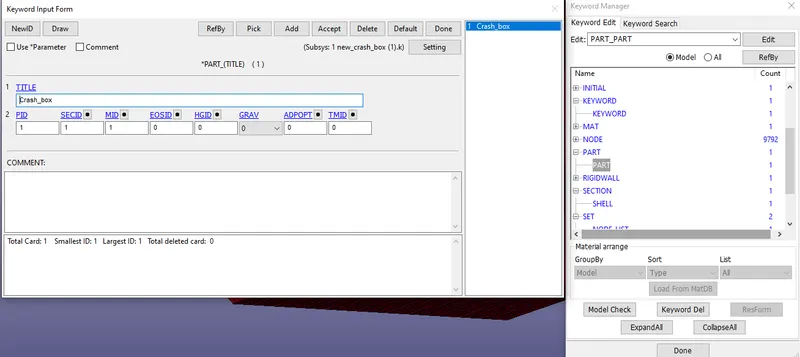
4.Create a part and assign the sectionID, MaterailID, and PartID.
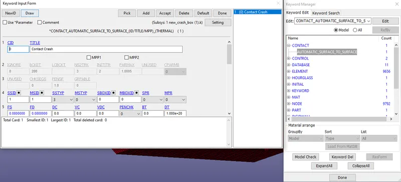
5.Create the contact of type automatic surface to surface type in the keyword manager and assign the slave and master ID's.
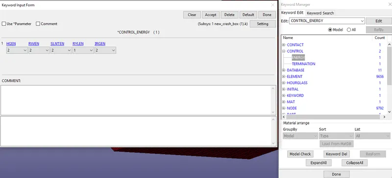
6.Create the energy under control tab and set it as below shown figure.
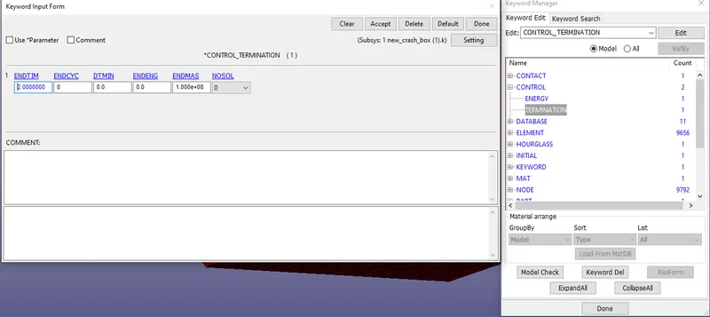
7.Create the termination under the control tab and enter the end time as 2.0000.
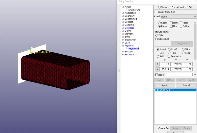
8.Create a rigidwall in the create entity of type Rigidwall Planar 1n+NL and values as shown.
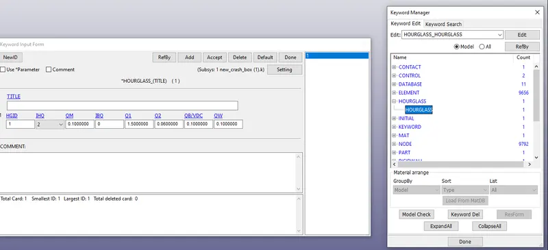
9.Create a hourglass under hourglass in the keyword manager and select the values as shown in below figure.
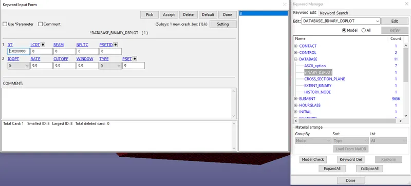
10.Create the binary d3plot under the database tab with DT value as 0.0200000.
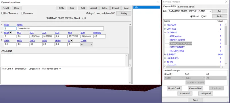
11.Create a cross section to the crashbox by following the values given below.
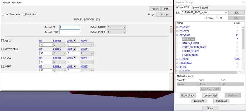
12.create a ASCII_option file under the database tab and select the Glsat,Matsum,Nodout,Rcforce,sleout and enter the DT value as 0.02.
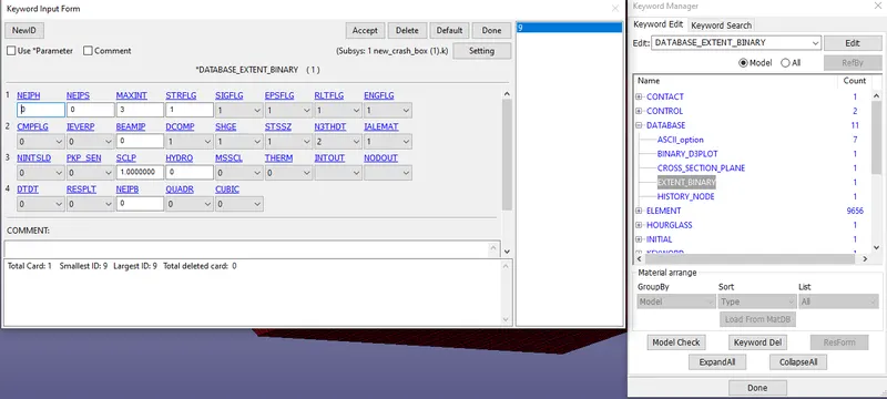
13.Create an extended binary under the database tab in the keyword manager with the given below values.
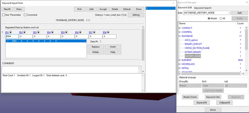
14.Create a history node in the database tab in the keyword manager by selecting a node as below.
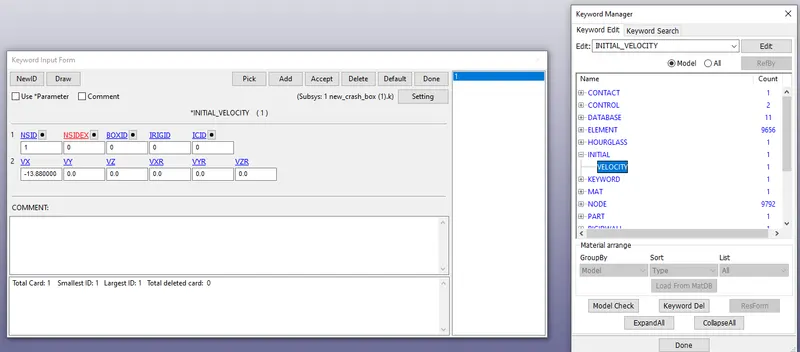
15.Create an initial velocity of -13.88mm/s as the crashbox has to move in -X direction.
16.Goto model checker and check for the errors in the keyword check tab if the error persists 0 then click on done.
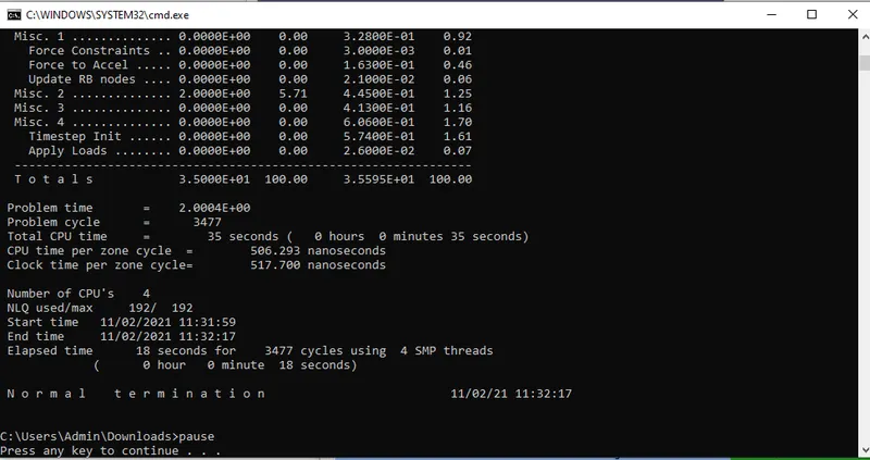
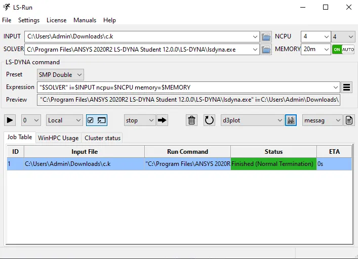
17.Save the file in the keyword file format and drop it in the LS-Run and the command window shows the progress and ends up with the normal termination.
Results:
The below images shows the stress strain generated in the crashbox for the given velocity and time.
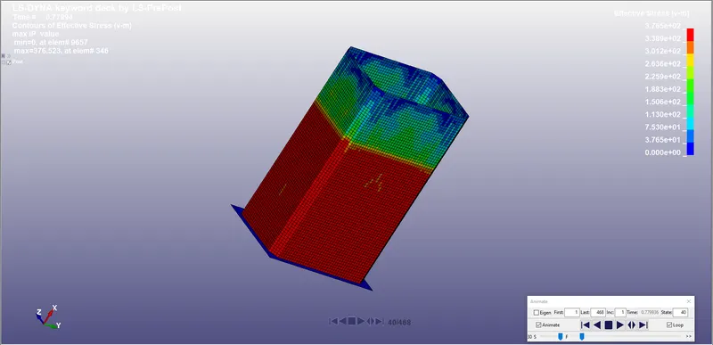
- Stress developed in the crashbox of 1.2mm thickness.
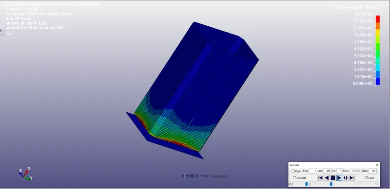
- Effective plastic strain developed in the crashbox of thickness 1.2 mm.
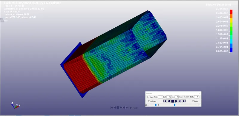
- Stress developed in the crashbox of 1.5mm.
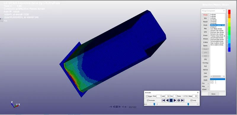
- Effective plastic strain developed in the crashbox of 1.5mm thickness.
- Acceleration of an element in the middle of the crashbox of 1.2mm thickness is plotted.
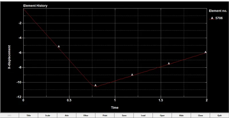
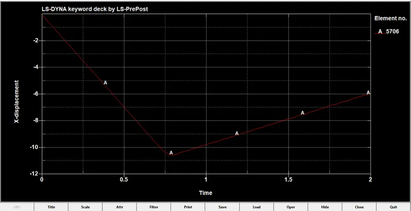
- Acceleration of an element in the center of crashbox of 1.5mm thickness is plotted below.
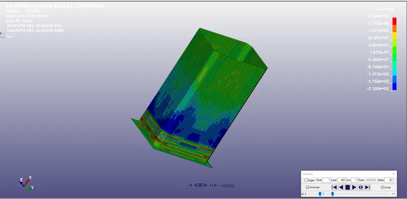
Maximum Directional Stress:
- Maximum directional stress are plotted in the X-direction of 1.2mm thickness crashbox.
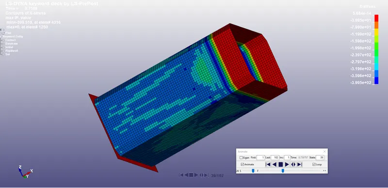
- Similarly maximum directional stress are for Crashbox of 1.5mm thickness.
- Maximum directional stress for the crashbox of thickness of 1.5mm in the Y-Axis is as shown below.
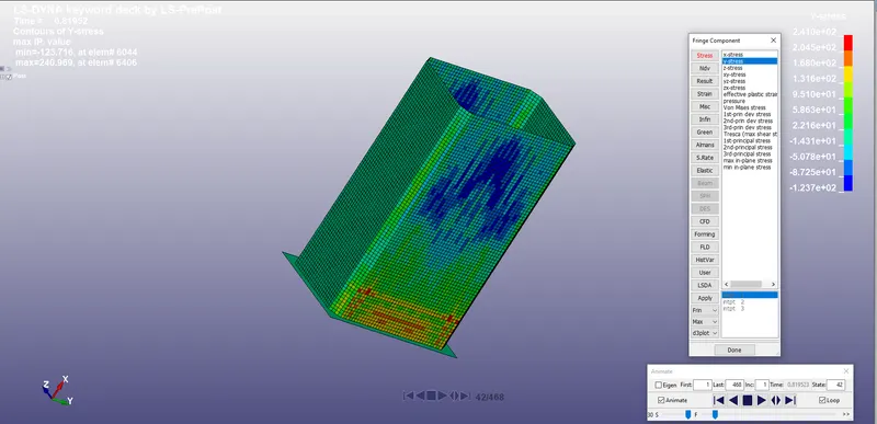
- Maximum directional stress for the crashbox of 1.5mm thickness in the Y-direction.
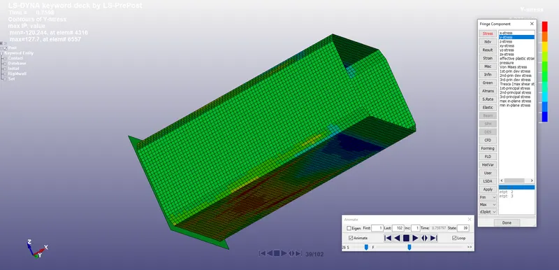
- There is difference in the maximum stress in the both crash simulations where the stress is lower in the crashbox of 1.5mm thickness and high in the crashbox of 1.2mm.
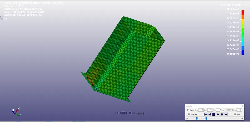
- The below figure shows the XY Strain for crash box of 1.2mm thickness.
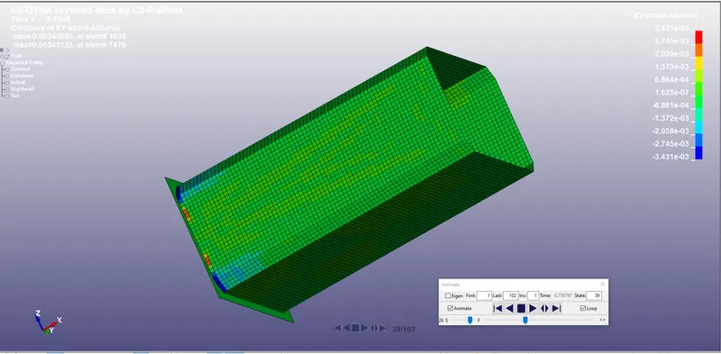
- The below figure shows the XY Strain for the Crashbox of 1.5mm thickness.
- Contours of X-Strain Almansi:
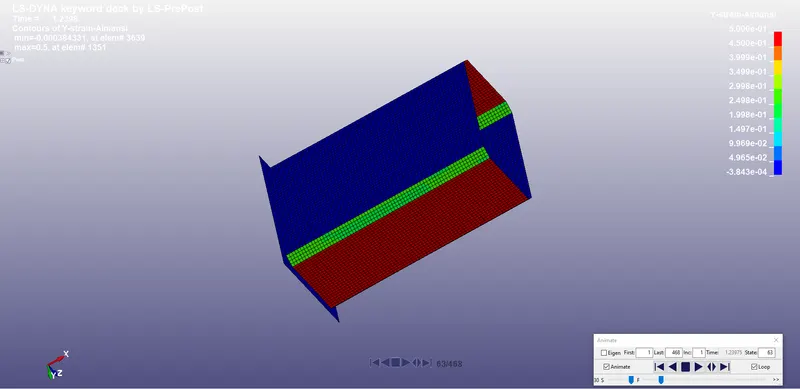
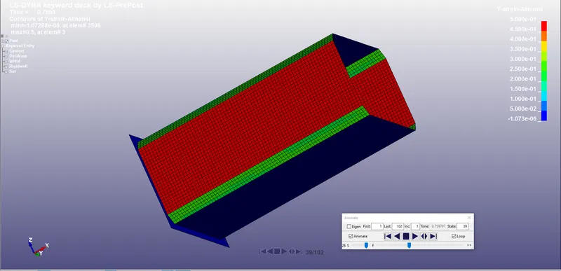
- Contours of Y-Strain Almans:
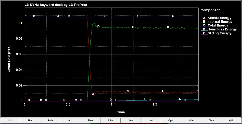
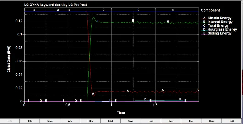
Energy Plots for both the Crash box simulations:
- The below graph represents the GLSTAT for the crashbox of 1.2mm thickness.
- The below graph represents the GLSTAT for the crashbox of 1.5mm thickness.
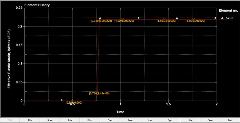
- The graph represents the effective plastic strain of an element in the center of the crashbox of 1.2mm thickness.
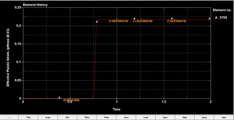
- Effective Plastic Strain of an element in the middle of the crashbox of thickness of 1.5mm thickness.
Conclusion:
Thus the crash box simulation for different thicknesses are performedwith given material and the results are plotted in the graphs and the required deliverables are attached below.