Week - 5 - Modelling Spotwelds
CRASH TEST ON A SHEET METAL WITH MODELLING OF SPOT WELD
AIM:
- To simulate a crash test for sheet metal by modelling spot weld using Beam and solid (Hexa) elements using LS-Dyna.
OBJECTIVE :
- To create the material card.
- To create a section card for thickness 1.5 mm.
- To assign material and section card to the part.
- To define a rigid wall.
- To assign initial velocity to the crash box.
- To define spot welds using beam elements.
- To create a section card and material card to Beam element.
- To define a contact interface.
- To define control card.
- To define the output database as both binary D3 plot and ASCII.
- Model checkup and run the simulation.
- To define spot welds using solid (Hexa) elements.
- To assign section card and material card to solid Hexa element.
- To define a contact interface.
- To run the simulation.
OUTPUT DELIVERABLES:
1. To create the Input .k file and output files (d3plot, glstat, sleout, rcforc)
2. To perform the animation of the final simulation.
3. To perform Cross-sectional force generated in the middle of the sheet metal (along its length)
4. To plot the Acceleration of a node in the middle of the sheetmetal (along its length)
5. To perform Maximum directional stress and strain along the length of the sheet metal (X strain, Y strain etc)
6. To plot of all energies (total, internal, kinetic, hourglass, sliding)
7. To compare the beam and solid elements spot weld results.
DATABASE:
ASSUMPTION AND INFORMATION :
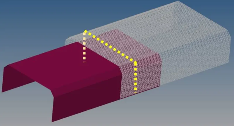
- The yellow line signifies the spotweld directions. You need to use 3-7 spotwelds along this line, in a symmetric manner, before running the simulation.
- The spotwelds should be modeled using beam elements and solid elements separately.
- While using solid elements, one spotweld should have one solid element.
- The axial and shear force should be compared among beam and solid elements.
- The same material card using *MAT_SPOTWELD should be used for both beam and solid elements.
- Use steel material data for *MAT_SPOTWELD cards and calibrate the failure data according to your results.
- The best simulation should have a failure at half of the termination time.
SOFTWARE USED:
Solver tool - LS-Prepost 4.7.17 and LS-Run 1.0.100838.
PROCEDURAL STEPS :
STEP 1 : Import the file.
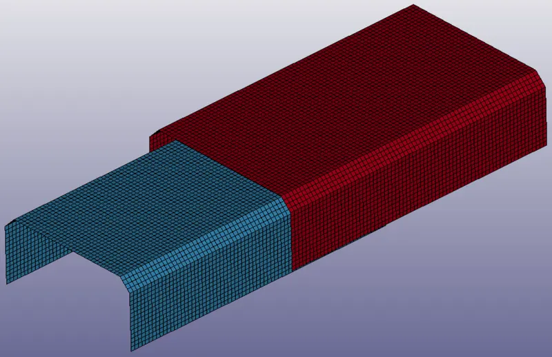
1. imported the K format type of file using LS-Prepost software.
2. File > Import > LS-Dyna keyword file > browsed to selected the K type of file > imported it.
STEP 2 : Check the keywords.
1. In order to check the keywords contained in the file we have to follow the below step
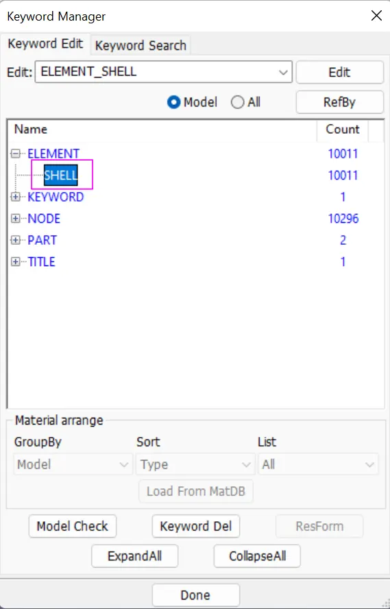
2. Side bar > model and part > keyword manager > checked the model.
3. Only shell elements presented in the model.Accordingh to analysis shell elements only needed.
STEP 3 : Check duplicate elements.
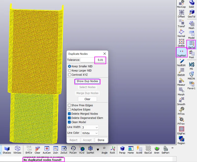
1. In order to check duplicate elements by firstly check the nodes the following steps.
2. Sidebar > element tools > check duplicates > selected nodes by area > Zero-duplicate nodes had been showed.
STEP 4 : Create the material card.
STEP 4a: Create the material card for bracket.
1. To assign the material card for sheetmetal by the following steps.
2. Side bar > model and part > keyword manager > MAT > all > selected the required materials for the brackets.
3. For brackets has assigned the material is 024-PIECEWISE_LINEAR_PLASTICITY.
4. Created new ID is 1 and give title is bracket_material and specified the values as gg-mm-ms unit system.
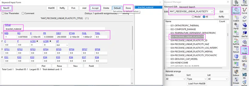
Where,
- Ro- density of the steel is 7.85 x 10⁻³ gm /mm³.
- E- youngs modulus of the steel is 210 x 10³ gm / mm ms².
- PR- poissons ratio of the steel is 0.3.
- SIGY - yiels stress of the steel is 250 gm / mm ms².
- ETAN- Tangent modulus is 2.1 x 10⁴.
STEP 5 : Create the section card for thickness 1.5mm.
- In this section, the element formulation, integration rule, nodal thicknesses, and cross-sectional properties are defined.
- All section identifiers (SECIDs) defined in this section must be unique, i.e., if a number is used as a section ID for a beam element then this number cannot be used again as a section ID for a solid element.
- The keyword cards in this section are defined in alphabetical order. Now, we are having shell elements, so we will use section shell.
- Created the section shell for brackets.
- Side bar > model and part > keyword manager >all > section >specified the thickness value is 1.5mm > created the new SECIDs for brackets.
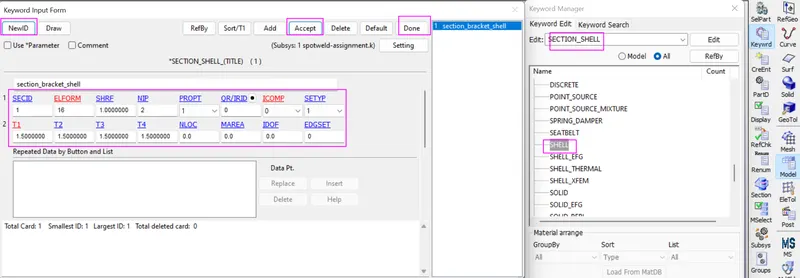
Where, SECID is Section ID.
ELFORM is Element formulation.
SHRF is Shear correction factor which scales the transverse shear stress.
NIP is Number of through thickness integration points.
STEP 6 : Assign the material card and section card to the bracket part.
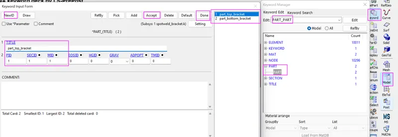
1. Already assigned the material card and section card for brackets, now we have to assigned the both cards to their respective btacket parts.
2. Inorder to create the brackets part by the following steps.
3. Side bar > model and part > keyword manager >model > part > assigned the MID and SECID cards to bracket parts.
STEP 7 : Define a rigid wall.
- The RIGIDWALL provides a easy way to define a contact between a rigid surface and nodal points of a deformable body, called slave nodes.
- A rigid wall is defined by a surface type and a group of slave nodes.
- Each wall can be fixed or moving. A rigid wall is a kinematic condition.So a rigid wall is created ahead of bracket. So that bracket should
crash into a rigid wall created. And rigid wall should create at some distance from bracket , because bracket have to move with some initial
velocity. Also, we have to take care about rigid wall normal vector direction. It should be facing bracket. In order to create rigid wall by the
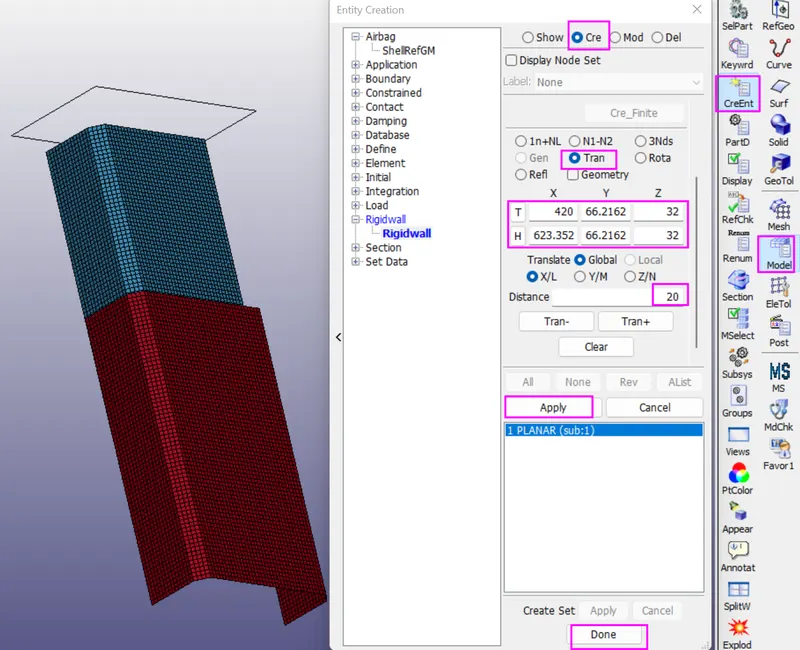
following steps. - Sidebar > model and part > create entity > rigidwall > create > cheked 1n+NL option > selected the one node > check Global and XL > rigidwall created.
- Then we have to move the rigidwall from bracket by the distance of 20 mm by the following steps
- At the same time > uncheked 1n+NL option >checked translate option > specified the distance is 20 mm > rigidwall created 20 mm distance from the bracket and also make sure vector normals of the bracket and rigidwall opposite to each other.so thats only the bracket rebounces after strike. if vector normals of the bracket and rigidwall is parallel to each other , bracket penetrated through the rigid wall thats not needed for the analysis.
STEP 8 : Assign the initial velocity to the bracket.
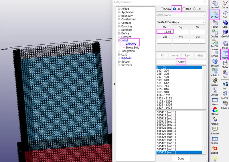
1. To provide initial velocity to the bracket by the following steps.
2. Sidebar > model > create entity > initial > velocity > pick by part > provide initial velocity in x direction as 13.88 mm/ms >done.
STEP 9 : Define the spot weld using beam elements.
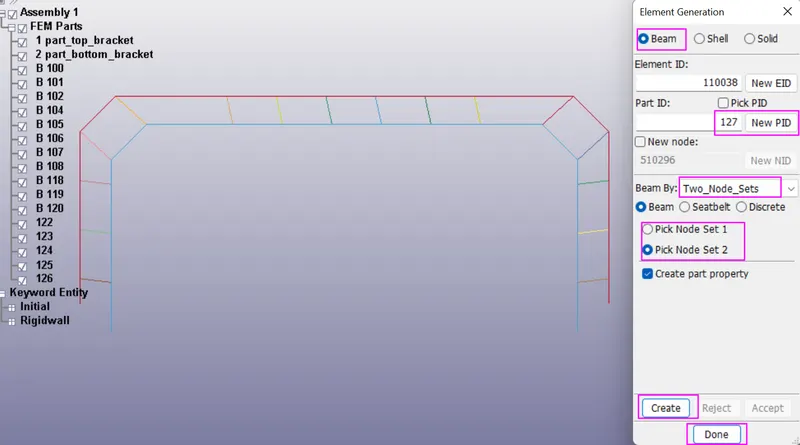
- To create a spot weld using Beam elements we have to follow
Element and Mesh > Element Generation > Beam > create new PID > Set beam by -set Two_node_sets > checked pick node set 1 - Also we need to create 3-7 spotwelds along this line, in a symmetric manner.
- In order to create the beam elements by the following steps,
- Side bar > mesh > element geneartion > checked beam option > set part id > selecet beam by two_set_nodes > pick node set 1- selected the node in top barcket > pick node set 2- selected the node in bottom bracket > create and done.
- And also created the no of beam elements between the top bracket and botton bracket .
STEP 10 : Assign the section card and material card to the beam element.
STEP 10A : Create the section card for the beam element.
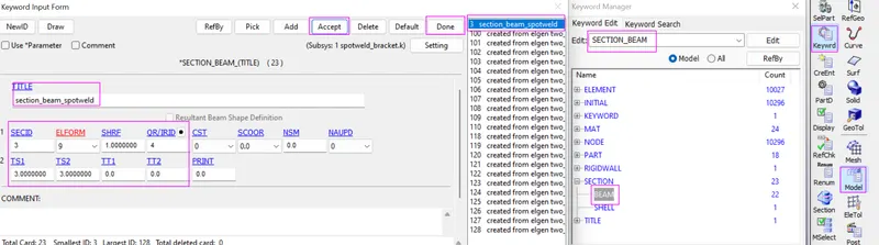
- In order to create the section card for the beam element by the following steps,
- Side bar > keyword manager > SECTION_BEAM > give title as section_beam_spotweld > give secid is 3 > Elform is 9 for spotweld beam, see *MAT_SPOTWELD (Type 100) > Shrf is 1.0 (default value) > Qr/ird is 4 > set beam thickness value (Ts1) is 3.0 > accept and done.
STEP 10B : Create the material card for spot weld beam element.
- To assign the material card for spotweld by the following steps.
- Side bar > model and part > keyword manager > MAT > all > selected the required materials for the spotweld.
- For spotweld has assigned the material is 100-SPOTWELD.
- Created new ID is 2 and give title is spotweld_material and specified the values as gg-mm-ms unit system.
- Consider the spotweld material use as a steel material card.
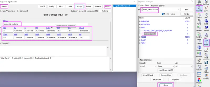
- Ro- density of the steel is 7.85 x 10⁻³ gm /mm³.
E- youngs modulus of the steel is 210 x 10³ gm / mm ms².
PR- poissons ratio of the steel is 0.3. - SIGY - yiels stress of the steel is 250 gm / mm ms².
- ETAN- Tangent modulus is 2.1 x 10⁴.
- TFIAL- time based failure is 5ms , which is exactly half of the simulation time.
- NRR - Axial force resultant Nrrf .
- NRS- Force resultant Nrsf / Shear stress based failure.
- NRT- Axial stress based failure.
- MRR- Torsional moment resultant at failure.
- MSS- Moment resultant MssF at failure.
- MST - Moment resultant MttF at failure.
STEP 10C : Assign the material card and section card to the spot weld beam element.
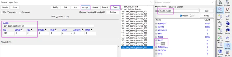
1. Already assigned the material card and section card for beam elements , now we have to assigned the both cards to their respective beam spot weld element part.
2. Inorder to create the beam spot weld part by the following steps.
3. Side bar > model and part > keyword manager >model > part > assigned the MID and SECID cards to beam spotweld respective parts.
STEP 11 : Define a contact interface.
- The keyword *CONTACT provides a way of treating interaction between disjoint parts.
- Now we have to define contact interface. Before defining contact card, first we have to create set data segment, in which we will create
segment for brackets (in which we will select those elements which are going to interact during simulation). - Define a set of segments with optional identical or unique attributes. For three-dimensional geometries, a segment can be triangular or
quadrilateral. For two dimensional geometries, a segment is a line defined by two nodes and the GENERAL option does not apply.
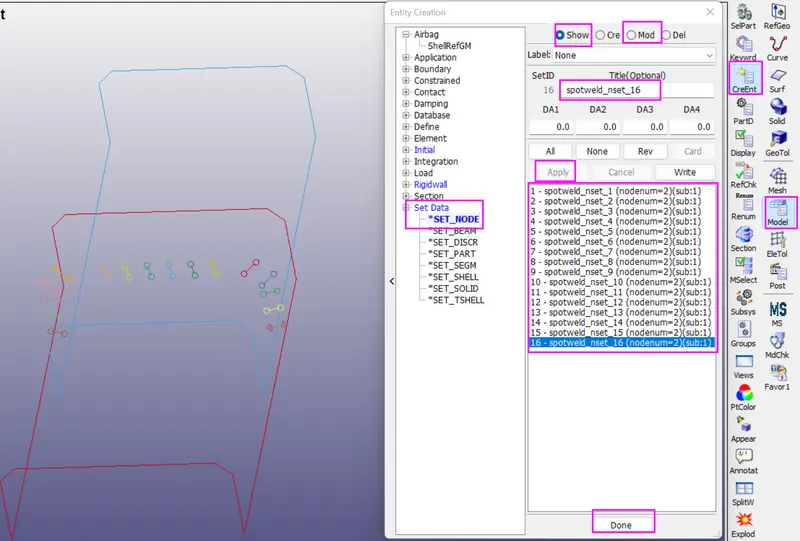
STEP 11A : Create a nodeset id for the beam element
- In order to create set of nodes we have to following the below steps.
- Side bar > model and part > create entity > set data > *SET_NODE > selected the nodes by pick > apply and done > created the nodeset ids for 16 beam elements .
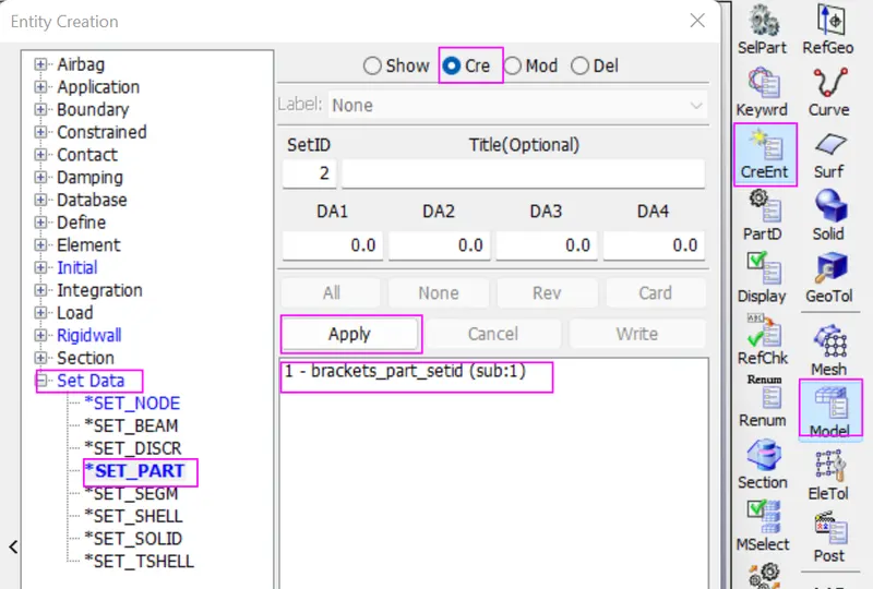
STEP 11B : Create a part set id for the Shell element.
- In order to create set of part set ids ,we have to following the below steps.
- Side bar > model and part > create entity > set data > *SET_PART > selected the part by pick > apply and done > created the partset ids for brackets.
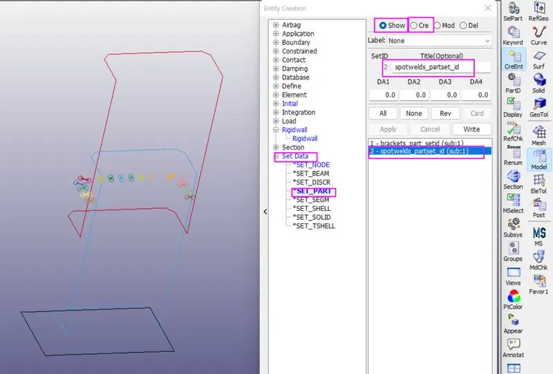
STEP 11C : Create a part set id for the beam element.
- In order to create set of part set ids ,we have to following the below steps.
- Side bar > model and part > create entity > set data > *SET_PART > selected the beam elements by pick > apply and done > created the partset ids for beams.
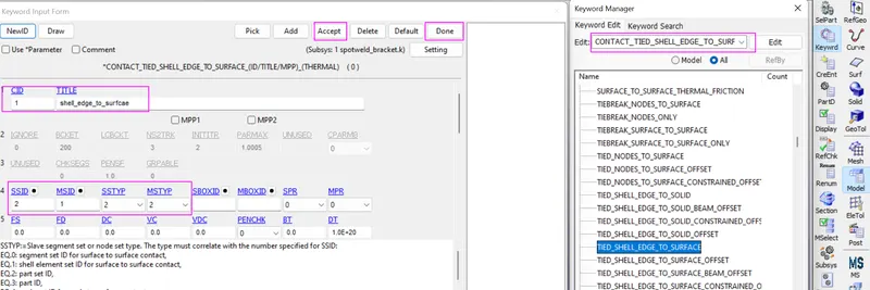
STEP 11D : Create a contact card for tied_Shell_Edge_To_Surface
- In order to create contact card, we have to select contact Tied_Shell_Edge_To_Surface for spotweld_assignment model.
- Sidebar> model and part > keyword manager > contact > TIED_SHELL_EDGE_TO_SURFACE > select SSTYP and MSTYP is 2 (for part set ids) > selected Beam part id for SSID and selected shell part id for MSID > accept and done.
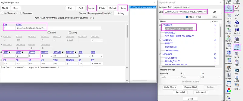
STEP 11E : Create a contact card for single surface.
- In order to create contact card, we have to select contact automatic single surface for spotweld_assignment model. In which slave is top and bottom shell brackets.
- Sidebar> model and part > keyword manager > contact > AUTOMATIC SINGLE SURFACE > select SSTYP is 2 and select SSID is 1 > accept and done.
STEP 12 : Create a control card
STEP 12 A : Create a control energy card.
1. The purpose of creating control energy card, provide controls for energy dissipation options.
2. In order to assign control energy card we have to following the below steps.
3. Sidebar > model and part > keyword manager > control > ENERGY >set HGEN as 2 > accept and done.
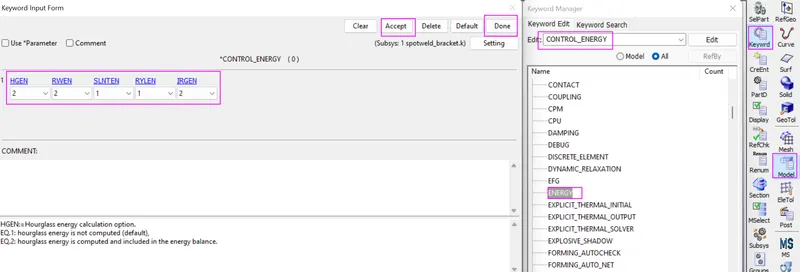
Where,
HGEN Hourglass energy calculation option.
RWEN Rigidwall energy dissipation.
SLNTEN Sliding interface energy dissipation option.
RYLEN Rayleigh energy dissipation option (damping energy dissipation):
IRGEN Initial reference geometry energy option.
STEP 12 B : Create a control hour glass card.
1. We use the reduced integration point formulation method which introduce the hourglass energy in the simulation.
2. To reduce hourglass energy, it is necessary to enable the hourglass card in the energy card from keyword card and enable hourglass card from
control keyword.
3. In order to assign control hourglass card we have to following the below steps.
4. Sidebar > model and part > keyword manager > control > HOURGLASS > set default values > accept and done.
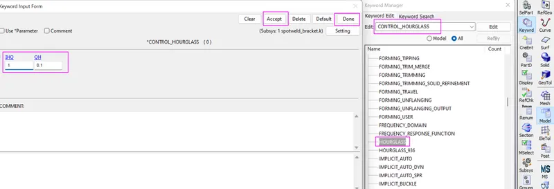
IHQ - Default hourglass control type.
QH - Default hourglass coefficient.
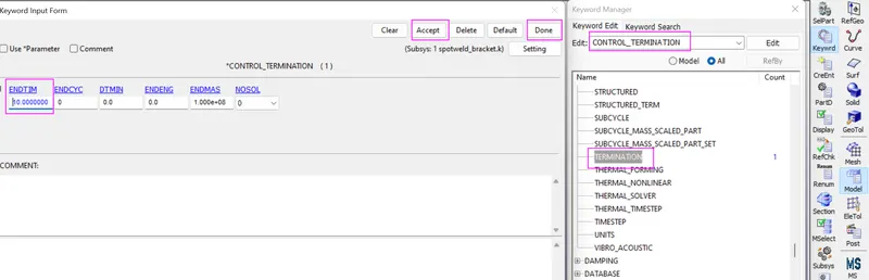
STEP 12 C : Create a control termination card.
1.The main purpose of control termination card is to stop the job.
2. In order to assign the control termination card by the following steps.
3. Side bar > model and part > keyword manager > control > termination > specify termination time is 10 ms > aceept and done.
Step 13: Define the output database
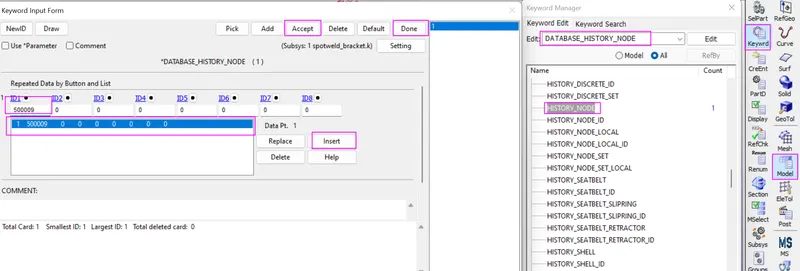
STEP 13 A : Create the history node for output database.
- DATABASE_HISTORY_NODE Control which nodes or elements are output into the binary history file.
- In order to create DATABASE_HISTORY_NODE by the following steps.
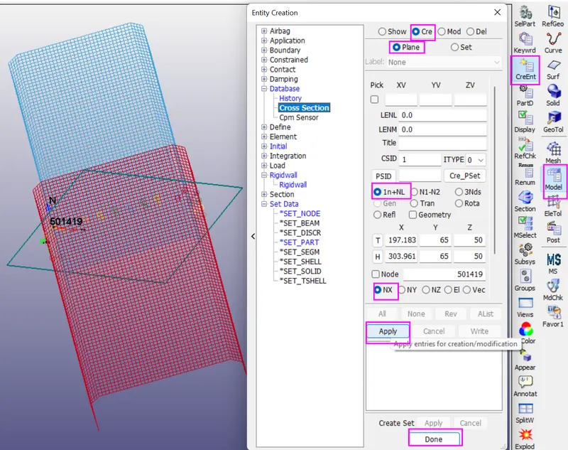
STEP 13B : Create a cross section
1. The purpose of creating cross section is to define a cross section for resultant forces written to ASCII file secforc.
2. So we have to create cross section at middle of crash box in order to get values of forces along the length of the crash box.
3. In order to create cross section we have to following the below steps.
4. Sidebar > model and part > create entity > database > create > checked plane > cheked 1n+NL option > selected the node > check Nx > apply and done.
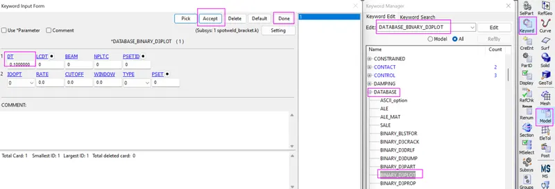
Step 13 C : Define the output database as Binary D3 plot.
1. DATABASE_BINARY_D3PLOT ensures d3 plot files which its stores stress strain contour of the entire deformed model.
2. In order to create the DATABASE_BINARY_D3PLOT by the fllowing steps.
3. Side bar > model and part > keyword manager > database > select DATABASE_BINARY_D3PLOT > provide DT value is 0.1 is a time interval between output states > accept & done.
Step 13 D : Define the output database as ASCII.
- ASCII can generate different outputs such as force generated in a contact like total energy and material energy etc.
- In which we will request output as GLSTAT, MATSUM,SECFORCE, SLEOUT, and RCFORCE.
- In order to create the ASCII by the fllowing steps.
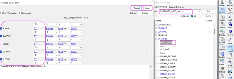
- Side bar > model and part > keyword manager > database > select ASCII_option > check GLSTAT,MATSUM ,NODOUT,SECFORCE, SLEOUT, RCFORCE,ELOUT and RWFORCE > specify all value is 0.1>accept & done.
STEP 14 : Model checkup and run the simulation.
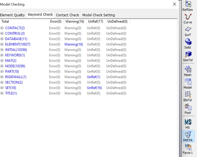
1. The model is checked for any errors before solving using model checker.
2. After all the errors are cleared, the drop test setup is saved and is ready to run in LS DYNA manager for solving the scenario.
3. Warnings we can ignore . once model checkis run , it will look like as shown in picture below.
STEP 15 : Run the simulation
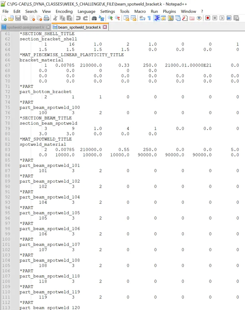
- Before running simulation we have to edit the K file and have to edit the KEYWORD ID, so that after simulation all files should be generated with proper format as shown.
1. To run the beam_spotweld_bracket using LS-run by the following steps.
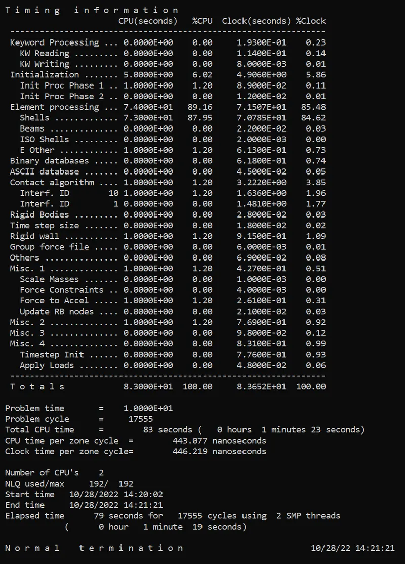
2. Title bar > file > run LS-dyna > runned the beam_spotweld_bracket file > achieved normal temination. it means the model is ready for post processing.
3. During simulation run window will popup as shown in picture below,
STEP 16 : Post processing
- In order to see simulation results , we have to open output file in LS-Prepost by the following steps.
- In LS-prepost -Title bar > file > open > LS -Dyna binary plot > selected the d3 plot file > visibled to see animation file.
- For plot the stress contour , go to sidebar > post >fringe component > selected in which results need for analysing the problem.
- For energy plot results , go to side bar > post > ASCII > selected in which enegy results (Glstat and Matsum) need for analysing the problem.
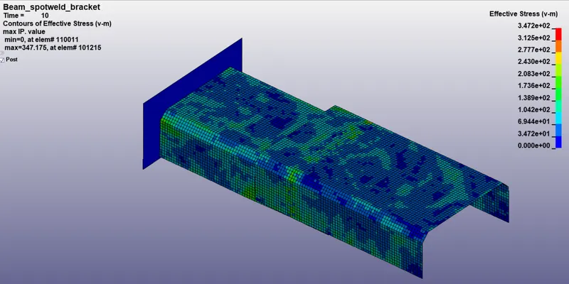
(1a) Contour plot of vonmisses stress in the bracket with beam spot weld model.
In order to see simulation results, we have to open output file .d3plot file in LS-PrePost
Max Effective stress = 347.15 gm / mm.ms²
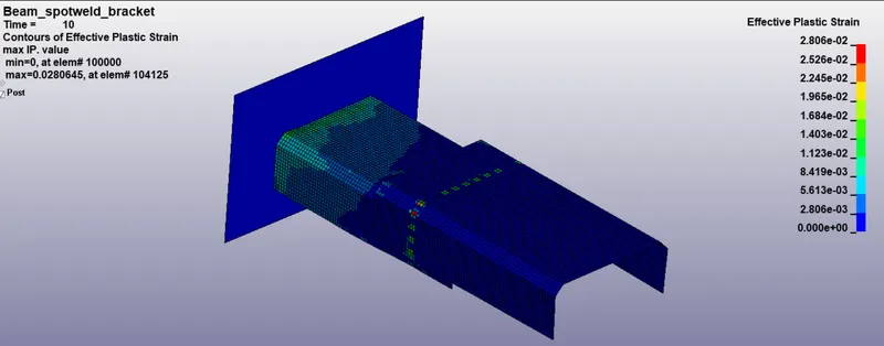
(1b) Contour plot of effective plastic strain in the bracket with beam spot weld model.
Max effective plastic strain = 0.028065
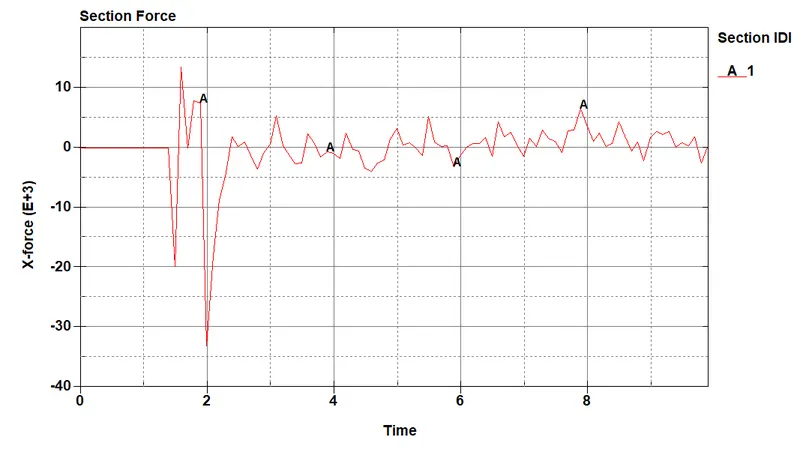
(2) Cross-sectional force generated in the middle of the bracket with with beam spot weld model.(along its length as X-direction)
Max force value = 1.34 * e+04 gm mm / ms²
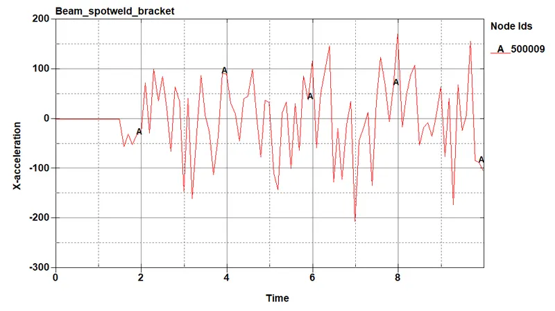
(3) Acceleration plot of a node in the bracket (along its length as X-direction).
Max acceleration at node 500009 = 1.71 * e+02 mm / ms²
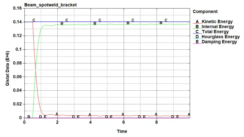
(4) Plot of energies of the brackets.
- Max kinetic energy = 1.4 *e+05gm mm / ms²
- Max internal energy = 1.37 *e+05 gm mm / ms²
- Total energy = 1.4 * e+05 gm mm / ms²
- Hourglass energy = 0
- Damping energy = 0
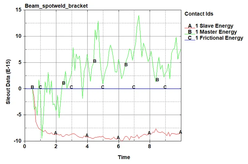
(5) Plot of sliding interface energies.
- Slave energy = -9.9 *e-15
- Master energy = 1.39*e-14
- Frictional energy = 0 (there is no friction created during simulation)
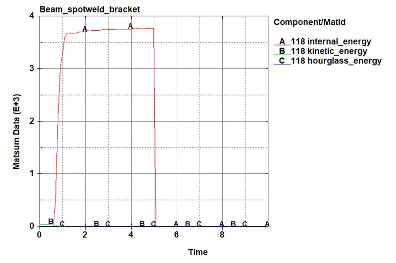
(6) Plot of material energies.
- Plot of material energies at beam element 118.
- Max kinetic energy = 4.3 * e+01gm mm / ms²
- Max internal energy = 3.7 * e+03 gm mm / ms²
- Hourglass energy = 0
(7) Plot of axial force and shear force generated in the Bracket with beam spot weld.
- Maximun axial force at spot weld beam element id iA110018 is 1.27 * e+03 gm mm / ms².
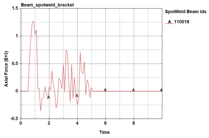
2. Maximun shear force at spot weld beam element id A110018 is 9.73 * e+02 gm mm / ms².
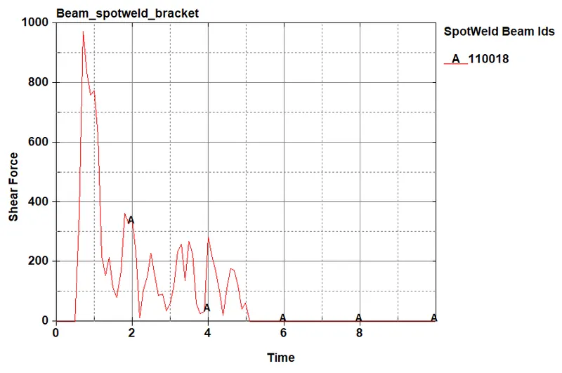
(8) Maximum directional stress along the length of the bracket with beam spot weld in X- direction.
Max x -stress = 238.61 gm / mm.ms²
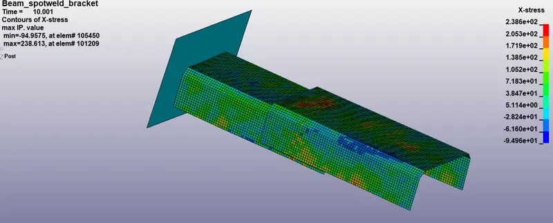
CASE II
STEP 1 :To define spot welds using solid (Hexa) elements.
- To create a spot weld using Solid elements we have to follow
- Side bar > Mesh > Element Editing > Hexa > selected the 8 nodes > created hexa elements between top and botton brackets > accept and done.
- Also we need to create 3-7 spotwelds along this line, in a symmetric manner.
- Now we have to pick four nodes from each shell element plates and then have to click on accept as shown in picture below.
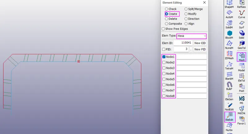
STEP 2 : Create the section card for spot welds using solid (Hexa) elements.
- In order to create the section card for the spot weld solid element by the following steps.
- Side bar > keyword manager > SECTION_SOLID > give title as section_solid_spotweld > give secid is 2 > Elform is 1 for spotweld solid > accept and done.
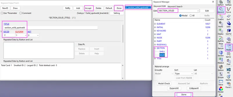
STEP 3 :Assign the section card and material card to part of the spot welds using solid (Hexa) element.
1. Already assigned the material card and section card for solid elements , now we have to assigned the both cards to their respective solid spot weld element part.
2. Inorder to create the solid spot weld part by the following steps.
3. Side bar > model and part > keyword manager >model > part > assigned the MID and SECID cards to solid spotweld respective parts.
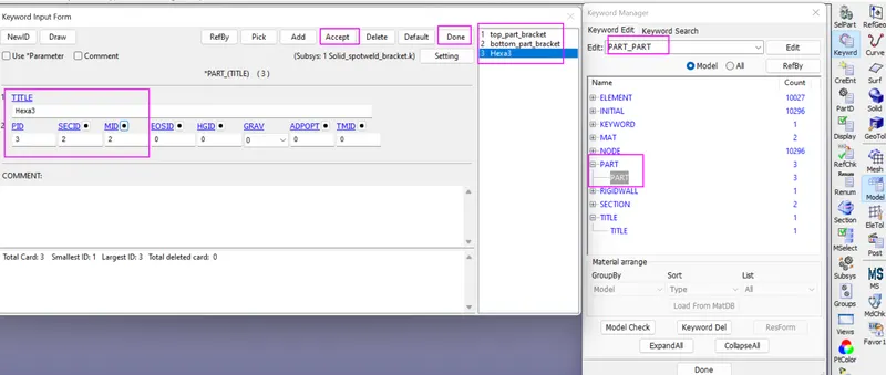
STEP 4 : Create a part set id for the Shell element and spotweld solid element.
- In order to create set of part set ids ,we have to following the below steps.
- Side bar > model and part > create entity > set data > *SET_PART > selected the bracket shell part by pick > apply and done > created the partset ids for brackets.
- Side bar > model and part > create entity > set data > *SET_PART > selected the created hexa parts by pick > apply and done > created the partset ids for spotweld solid element.
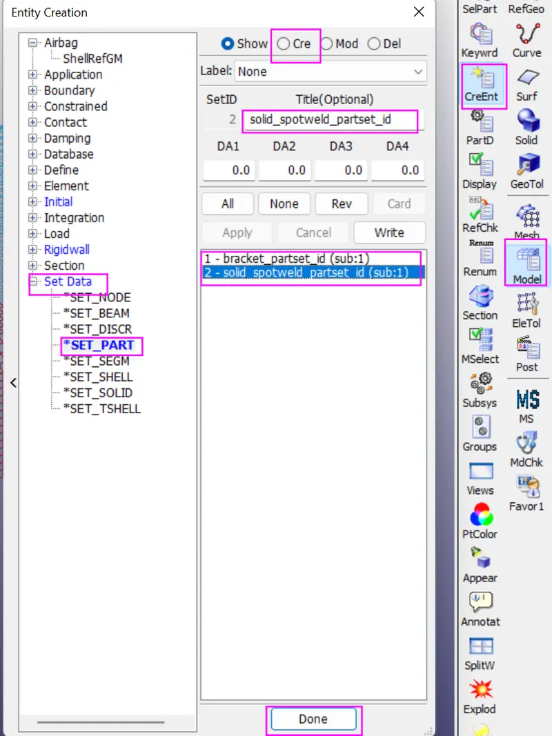
STEP 5 : Define a contact interface of spotweld
- In order to create contact card, we have to select contact spotweld for solid spotweld_assignment model.
- Sidebar> model and part > keyword manager > contact > CONTACT_SPOTWELD > select SSTYP and MSTYP is 2 (for part set ids) > selected solid part id for SSID and selected shell part id for MSID > accept and done.
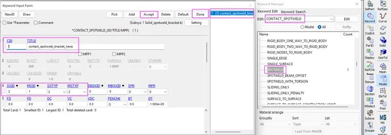
STEP 6 : Define a contact interface of automatic single surface
- In order to create contact card, we have to select contact automatic single surface for spotweld_assignment model. In which slave is top and bottom shell brackets.
- Sidebar> model and part > keyword manager > contact > AUTOMATIC SINGLE SURFACE > select SSTYP is 2 and select SSID is 1 > accept and done.
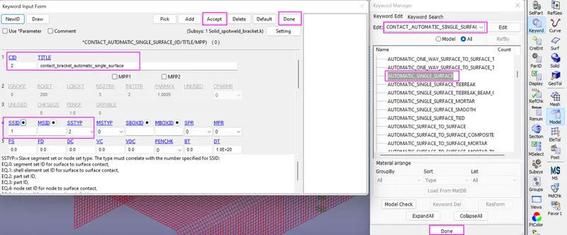
STEP 7 : Model checkup and run the simulation.
1. The model is checked for any errors before solving using model checker.
2. After all the errors are cleared, the drop test setup is saved and is ready to run in LS DYNA manager for solving the scenario.
3. Warnings we can ignore . once model checkis run , it will look like as shown in picture below.
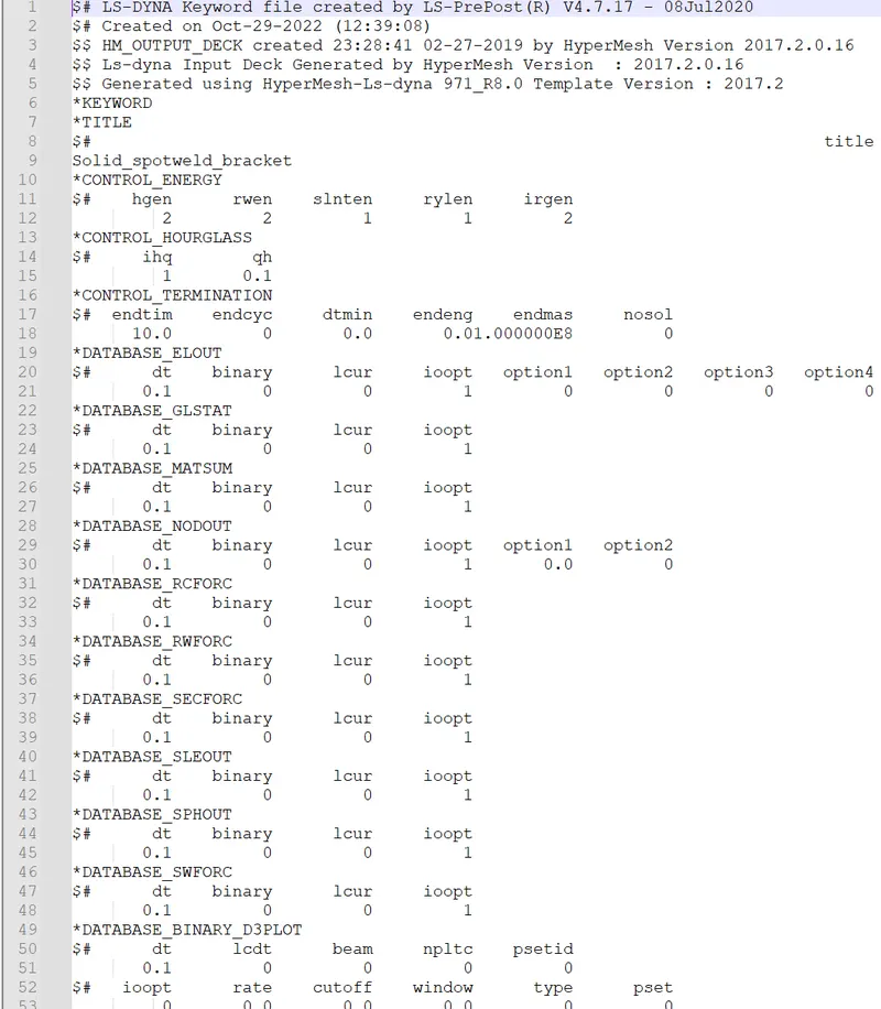
1. To run the _spotweld_bracket using LS-run by the following steps.
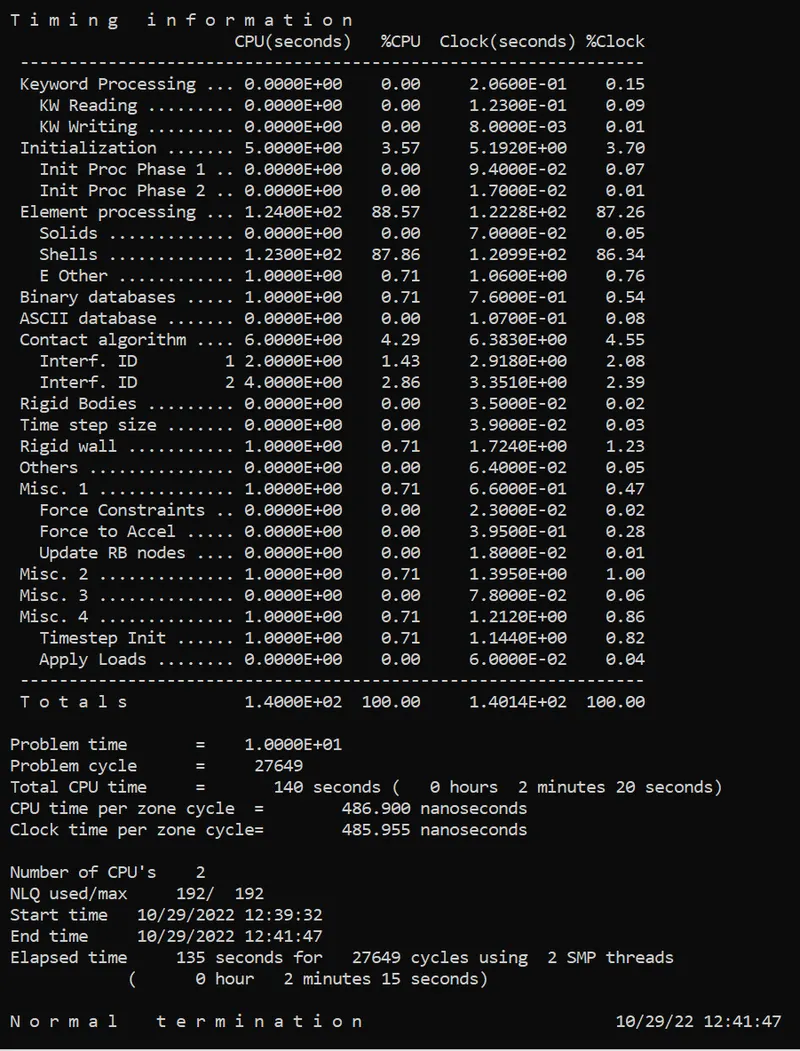
2. Title bar > file > run LS-dyna > runned the solid_spotweld_bracket file > achieved normal temination. it means the model is ready for post processing.
3. During simulation run window will popup as shown in picture below,
STEP 8 : Post processing
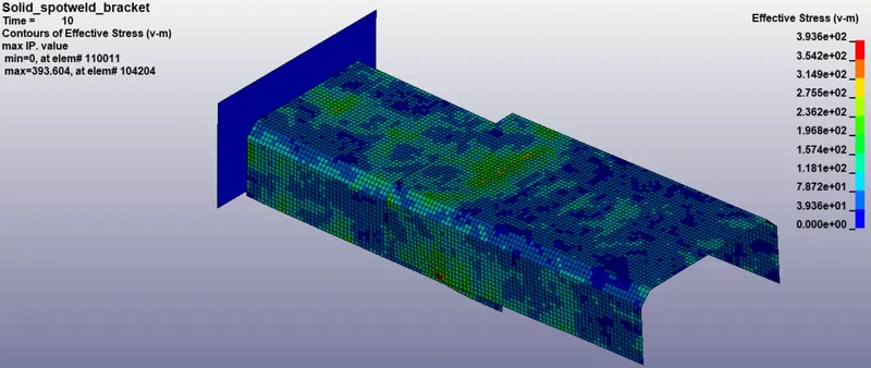
(1a) Contour plot of vonmisses stress in the bracket with solid spot weld model.
In order to see simulation results, we have to open output file .d3plot file in LS-PrePost
Max Effective stress = 393.6 gm / mm.ms²
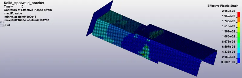
(1b) Contour plot of effective plastic strain in the bracket with beam spot weld model.
Max effective plastic strain = 0.0216904
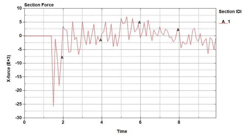
(2) Cross-sectional force generated in the middle of the bracket with with solid spot weld model.(along its length as X-direction)
Max force value = 7 * e+03 gm mm / ms²
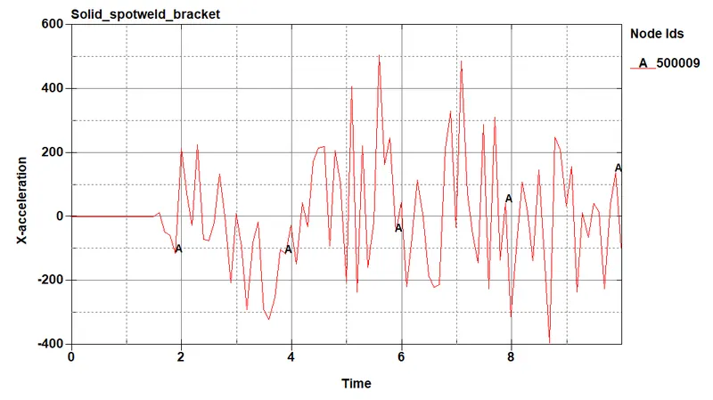
(3) Acceleration plot of a node in the bracket (along its length as X-direction).
Max acceleration at node 500009 = 5 * e+02 mm / ms²
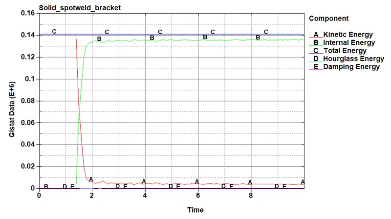
(4) Plot of energies of the brackets.
- Max kinetic energy = 1.41 * e+05gm mm / ms²
- Max internal energy = 1.36 *e+05 gm mm / ms²
- Total energy = 1.4 * e+05 gm mm / ms²
- Hourglass energy = 2.57 * e+02
- Damping energy = 0
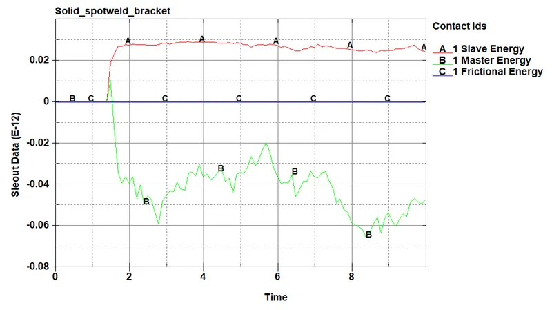
(5) Plot of sliding interface energies.
- Slave energy = 2.91 * e-14
- Master energy = 1.06 * e-14
- Frictional energy = 0 (there is no friction created during simulation)
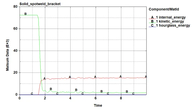
(6) Plot of material energies.
- Max kinetic energy = 7.25 * e+04gm mm / ms²
- Max internal energy = 1.58 * e+04 gm mm / ms²
- Hourglass energy = 0
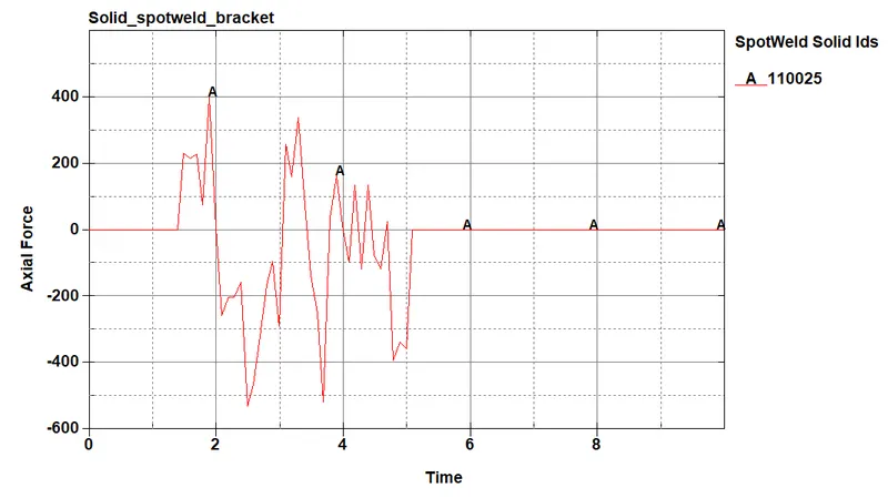
(7) Plot of axial force and shear force generated in the Bracket with solid spot weld.
- Maximun axial force at spot weld solid element id is A110025 is 4 * e+02 gm mm / ms².
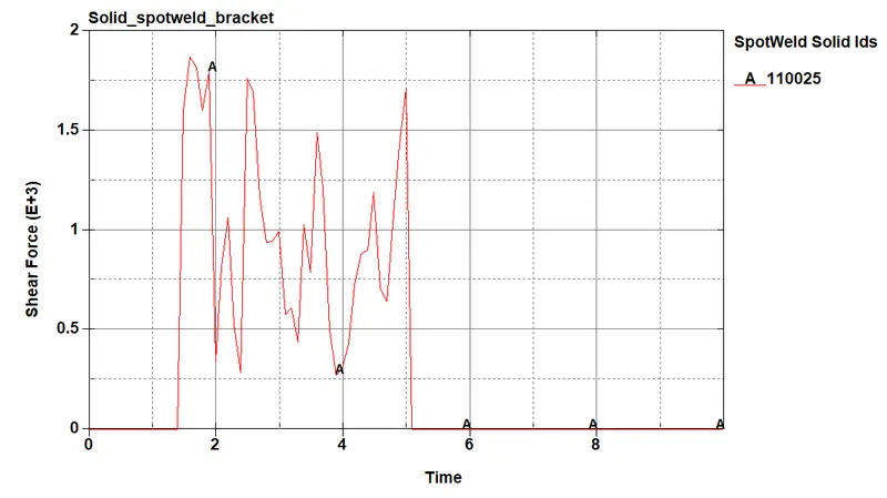
2. Maximun shear force at spot weld solid element id is A110018 is 1.8 * e+03 gm mm / ms².
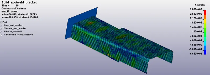
(8) Maximum directional stress along the length of the bracket with solid spot weld in X- direction.
Max X stress = 288 gm / mm ms²
Comparison of acceleration and stress/strain plots of Beam spotweld bracket model / solid spotweld bracket model.
(a) Comparison of acceleration plot of node at 500009
Max acceleration of beam spotweld_bracket at node 500009 = 5 * e+02 mm / ms²
Max acceleration of Solid spotweld_bracket at node 500009 = 1.71 * e+02 mm / ms²
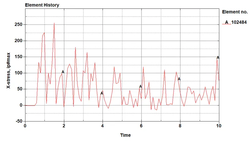
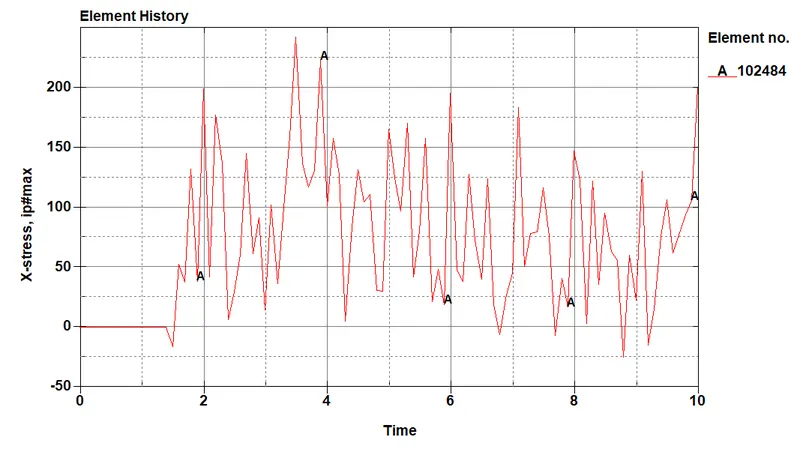
(b) Comparison of x-stress at element 102484
Max x-stress of beam spotweld_bracket at element 102484 is 2.56 * e+02 gm / mm.ms²
Max x-stress of Solid spotweld_bracket at element 102484 is 2.42 * e+02 gm / mm.ms²
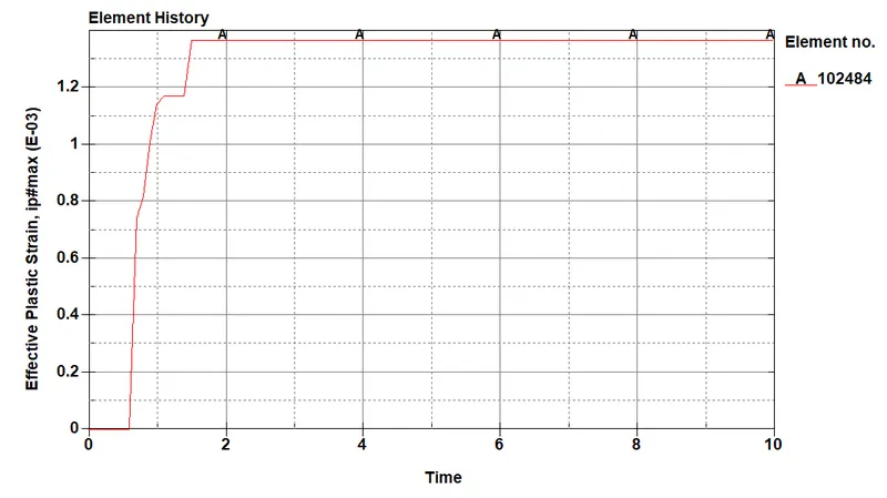
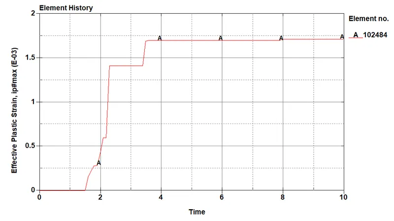
(c) Comparison of strain at element 102484
Max effective plastic strain beam spotweld_bracket at element 102484 is 1.36 * e-03
Max effective plastic strain of Solid spotweld_bracket at element 102484 is 1.71 * e-03
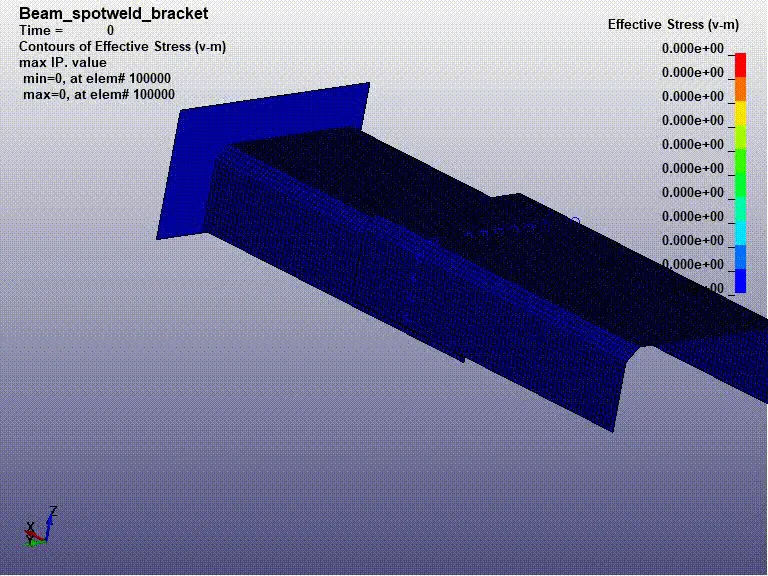
Final simulation of beam spotweld_bracket
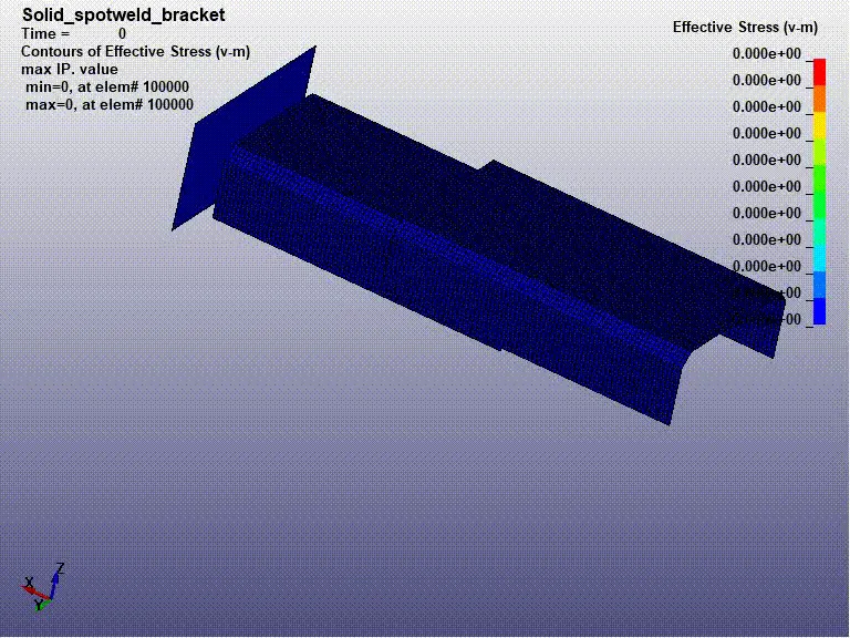
Final simulation of Solid spotweld_bracket
CONCLUSION :
| S.NO | OUTPUT DELIVERABLES | BRACKET WITH BEAM_SPOTWELD | BRACKET WITH (HEXA3) SOLID_SPOTWELD |
| 1. | Max Effective stress (Von misses) | 347.15 gm/ mm.ms² | 393.6 gm / mm.ms² |
| 2. | Max effective plastic strain | 0.02806 | 0.02169 |
| 3. |
Max cross-sectional force generated (along its length as X-direction) |
13.4 * e+03 gm mm / ms² | 7 * e+03 gm mm / ms² |
| 4. |
Acceleration plot at node 500009 (along its length as X-direction). |
1.71 * e+02 mm / ms² | 5 * e+02 mm / ms² |
| 5. | Energies developed |
Max kinetic energy = 1.4 *e+05gm mm / ms² Max internal energy = 1.37 *e+05 gm mm / ms² Total energy = 1.4 * e+05 gm mm / ms² |
Max kinetic energy = 1.41 * e+05gm mm / ms² Max internal energy = 1.36 *e+05 gm mm / ms² Total energy = 1.4 * e+05 gm mm / ms² |
| 6. | Sliding interface energies. |
Slave energy = -9.9 *e-15 Master energy = 1.39*e-14 Frictional energy = 0 |
Slave energy = 2.91 * e-14 Master energy = 1.06 * e-14 Frictional energy = 0 |
| 7. |
Material energies at beam element 118. |
Max kinetic energy = 4.3 * e+01gm mm / ms² Max internal energy = 3.7 * e+03 gm mm / ms² |
Max kinetic energy = 7.25 * e+04gm mm / ms² Max internal energy = 1.58 * e+04 gm mm / ms² |
| 8. |
Maximum axial force |
At beam element id iA110018 is 1.27 * e+03 gm mm / ms². |
At solid element id A110025 is 4 * e+02 gm mm/ ms². |
| 9. | Maximum shear force | At beam element id iA110018 is 9.73 * e+02 gm mm / ms². | At solid element id A110025 is 1.8 * e+03 gm mm / ms². |
| 10. | Maximum directional stress along the length in X- direction. | 238.61 gm / mm.ms² | 288 gm / mm ms² |
| 11. | Max x-stress at element 102484 | 2.56 * e+02 gm / mm.ms² | 2.42 * e+02 gm / mm.ms² |
| 12. | Max effective plastic strain at element 102484 | 1.36 * e-03 | 1.71 * e-03 |
- Max effective stress in bracket with beam spot weld is less than the bracket with hexa3 solid spot weld, because solid element material is more size compared to beam tubular cros section size, so hexa3 solid spot weld was induced more stress than the beam spot weld bracket.
- Max effective plastic strain is bracket with beam spot weld also little more than the bracket with hexa3 solid spot weld, because hexa3 solid spot weld has thick cross section compared to bracket with beam spot weld has tubular cross section.
LEARNING OUTCOMES:
- The spot welds are modelled successfully using Beam and solid elements for the same sheet metal components.
- The cards and other keywords are assigned successfully for spot-welds and brackets.
- Simulation has been done successfully.
- All the output requests have been calculated.