Week 9-Creation of 1D Connectors Challenge
CREATION OF 1D CONNECTORS IN FRAME ASSEMBLY
AIM :
- To do 2D meshing on the assembly of frame parts as per the given data.
- To create the connector and attach the various parts of the frame assembly as per the given data.
GIVEN DATA :
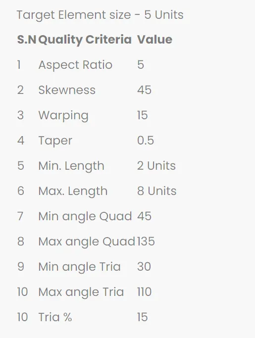
(1) 2D MESHING QUALITY CRITERIA
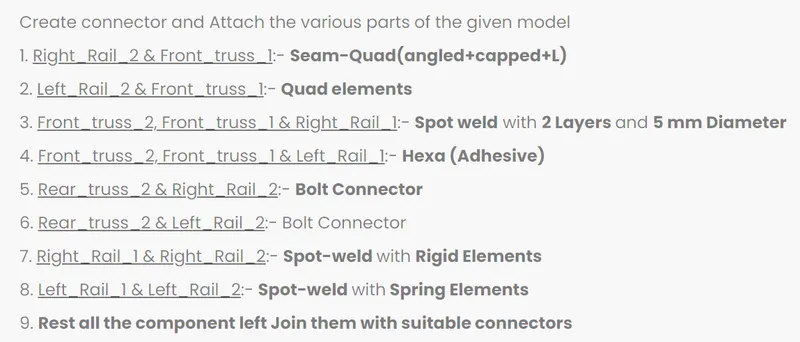
(2) CONNECTIONS DATA
GIVEN MODEL :
Hypermesh file of frame assembly
SOFTWARE USED :
Preprocessing software - Hyperworks Desktop 2022.
PROCEDURAL STEPS:
PART A : 2D MESHING ON THE ASSEMBLY OF FRAME PARTS
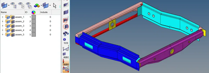
STEP1A : IMPORTING THE ASSEMBLY OF FRAME PARTS.
- Imported the assembly of frame parts by hyperworks desktop environment.
- File > import > model > browsed to selected the hm file of the model > imported it.
CAD model of frame assemby
STEP 1B : GEOMETRIC CLEANUP ON THE ASSEMBLY OF FRAME PARTS.
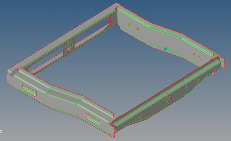
- Set as by topo mode to check if there's any extra surface or free edges or missing surfaces
are present or not. but it had no frre edges and missing surfaces present in between the surfaces. - Enable wireframe geometry mode and then try to observe and find irragularities and
discontinuities in the model. but those are not present in the model , If found then fix it manual.
Geometric cleanup of frame assemby
STEP 1C : SET THE MESH PARAMETERS AND QUALITY CRITERA VALUES
- Before go to the 2D meshing process, set the mesh parametes values and quality criteria values as per the given data.
- Title bar > Preferences > parameter file settings > basic > changed the parameter values as per given data.
- Title bar > Preferences > quality criteria file settings > changed the parameter values as per given data.
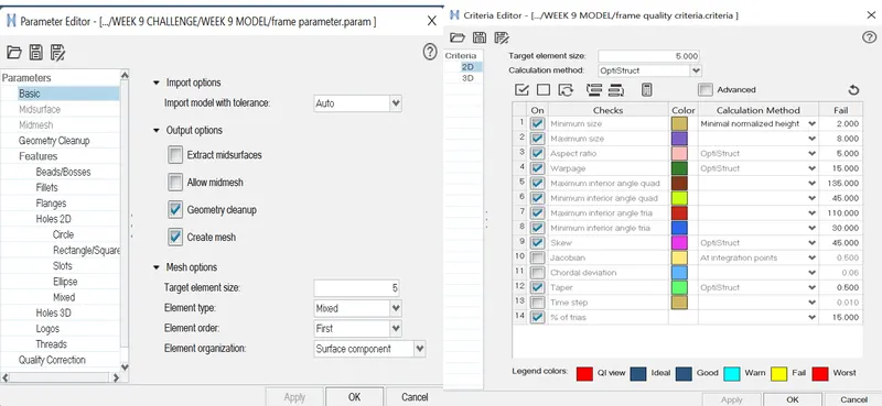
STEP 1D: 2D MESHING ON THE ASSEMBLY OF FRAME PARTS.
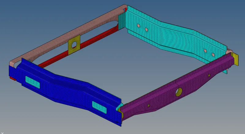
- Performed meshing on the model by automesh method.
- Mainmenu > 2D > automesh > set the target element size = 5mm > selected the surfaces > meshed it.
- Achieving proper mesh flow was followed by the below steps.
- Reduced the trias concentration by Mainmenu > 2D > edit element > split > selected the elements >
draw a spliiting line bypoints > splitted the elements.
Then Mainmenu > 2D > edit element > combine > selected 2 trias > combined into quads. - (or) Mainmenu > 2D > split > click refine elements > selected the elements by path > splitted intoelements.Then Mainmenu > 2D > edit element > combine > selected 2 trias > combined into quads.
- Mainmenu > 2D > quality index > cleanup tools > Drag tria elements and combine tria elements >reduced the no of trias .
- Reduced the no of trias by Mainmenu > 2D > replace > node with other node > disabled the tria element.
- After spliitting the elements to perform smmoth operation to get uniform mesh flow by,Mainmenu > 2D > smooth > plates > selected the elements > set the iterationvalues as 1 or 10 >smoothed it.
- (or) Mainmenu > 2D > quality index > cleanup tools > smooth > selected the elements > smoothed it.
- After splitting the elements alignment node will be changed , so nodes will aligned by Mainmenu > geometry > node edit > aliogn node > selected the 1st and 2nd end node and selected nodes needs to be aligned.
- To get the proper alignment of node with midsurface construction line by Mainmenu > tools > project > click to line option > selected the nodes wants to align and selected theconstruction line and vector by nodes > alligned it.
- To improve the mesh flow by using rebuild mesh option,Mainmenu > 2D > rebuild mesh > selected the elements > proper mesh flow got it.
Surface meshing of frame assembly parts
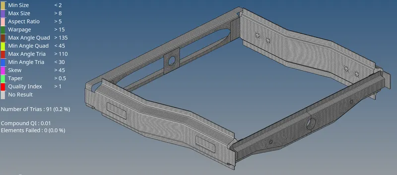
STEP 1E: CHECKING AND FIXING THE ELEMENTS FAILING FOR QUALITY CRITERIA.
1. Mainmenu > 2D > quality index > cleanup tools > set display threshold as fail > idenetified the elements which are failing for quality .
2. Then , go to mainmenu > tools > check elements > 2D > set the quality criteria values a sper the gevendata.
3. Check the warpage quality by selected the elements which are failing for the warpage by save failed option.then go to mainmenu > tool >mask > selected the elements by retrieve > mask > reverse showed the elements failing for warpage.
4. Then go to the unmask adjacent option showed the adjacent elements, then its fixed by place node ,remesh,rebuild mesh options , element optimization and smooth in quality index.
5. Then fixed the elements which are failing for aspect ratio, min length , max length , skewness , taper , min & max angle trias and min & max angle quads.
Surface meshing of frame assembly parts with no quality issues
PART B : CREATION OF CONNECTION BETWEEN THE VARIOUS PARTS OF THE FRAME ASSEMBLY.
STEP 2A : Creation of Seam-quad ( angled + capped + L ) weld connection between right_rail_2 and front_truss _1
1. Selected1D/2D → Connectors → Seam option.
2. Now selected the location, where the Weld has to be created, by clicking the “node list”.
3. Ticked the checkbox of “retain nodes” option, to retain the position of the nodes, while creating and realizing a
connector.
4. Specified the “spacing” value is 5 which is equal to target element length and selected the “comps” is right_rail_2 and front_truss _1 option under “connect what”, in order to create the weld
between those two components.
5. Specified the “tolerance” valueis 10mm based on the distance between the two components.
6. Selected the type as “seam-quad (angled+capped+L)”.
7. Clicked on the “create” button, the seam weld created.
Seam-quad ( angled + capped + L ) weld connection between right_rail_2 and front_truss _1
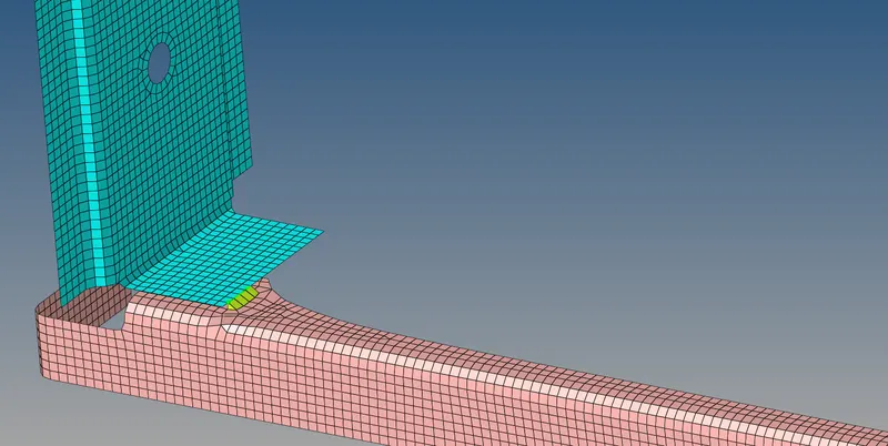
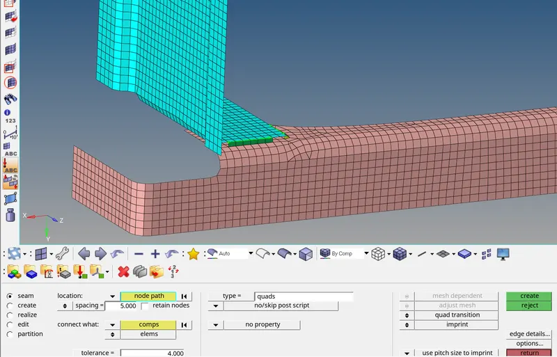
STEP 2B : Creation of Seam(quad elements ) weld connection between right_rail_2 and front_truss _1
1. Selected1D/2D → Connectors → Seam option.
2. Now selected the location, where the Weld has to be created, by clicking the “node list”.
3. Ticked the checkbox of “retain nodes” option, to retain the position of the nodes, while creating and realizing a
connector.
4. Specified the “spacing” value is 5 which is equal to target element length and selected the “comps” is right_rail_2 and front_truss _1 option under “connect what”, in order to create the weld
between those two components.
5. Specified the “tolerance” valueis 4 mm based on the distance between the two components.
6. Selected the type as “seam(quad elements)”.
7. Clicked on the “create” button, the seam weld created.
Seam(quad elements ) weld connection between right_rail_2 and front_truss _1
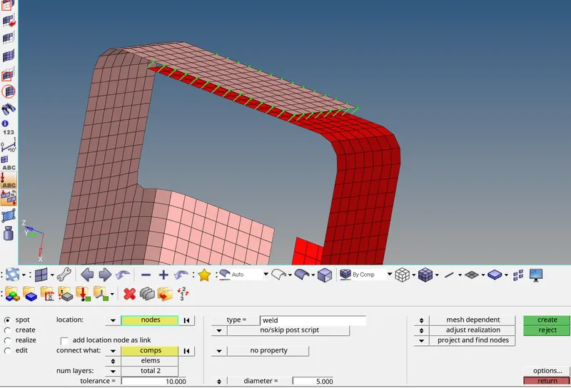
STEP 2C : Creation of spot weld connection between front_truss _1 , front_truss_2 and right rail_1
- Selected 1D/2D → Connectors → Spot option.
- Now selected the location, where the Weld has to be created, by clicking the “node list”.
- Selected the “comps” is front truss1 and front truss 2 option under “connect what”, in order to create the weld between those two components.
- Selected the number of layer is 2 nos to be welded, under “num layers” option.
- Specified the “tolerance” valueis 10 based on the distance between the two components.
- Specified the diameter is 5 mm as per the given data.
- Selected the type as “weld”.
- Click on the “create” button, created the spot weld.
Spot weld connection between front_truss _1 and front_truss_2
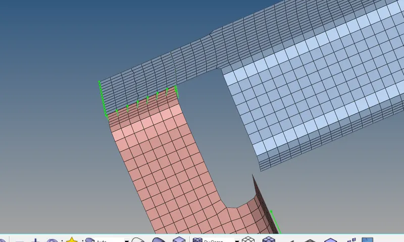
Spot weld connection between front_truss _1 and right_rail_1
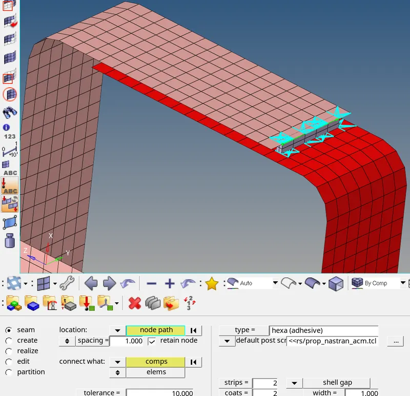
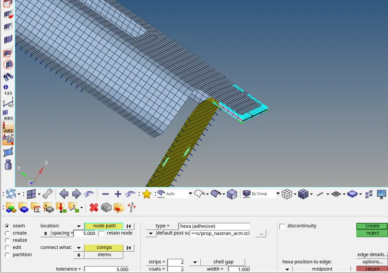
STEP 2D : Creation of seam hexa adhesive weld connection between front_truss _1 , front_truss_2 and left_rail_1
- Selected 1D/2D → Connectors → Seam option.
- Now selected the location, where the Weld has to be created, by clicking the “node list”.
- Tick the checkbox of “retain nodes” option, to retain the position of the nodes, while creating and realizing a connector.
- Specified the “spacing” value is 1 and select the “comps” is left rail_1 and front truss_1 option under “connect what”, in order to create the weld between those two components.
- Specified the “tolerance” value is 10 , based on the distance between the two components.
- selected no of strip as 2 and coat as 2 and width is 1mm
- Selected the type as “hexa (adhesive)”.
- Click on the “create” button,created the seam weld connections.
Seam hexa adhesive weld connection between front_truss _1 and left_rail_1
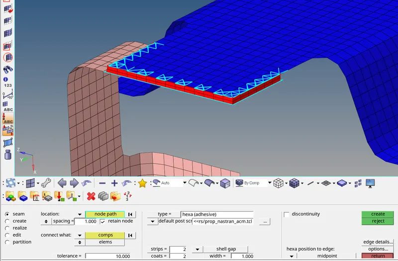
Seam hexa adhesive weld connection between front_truss _1 and front_truss _2
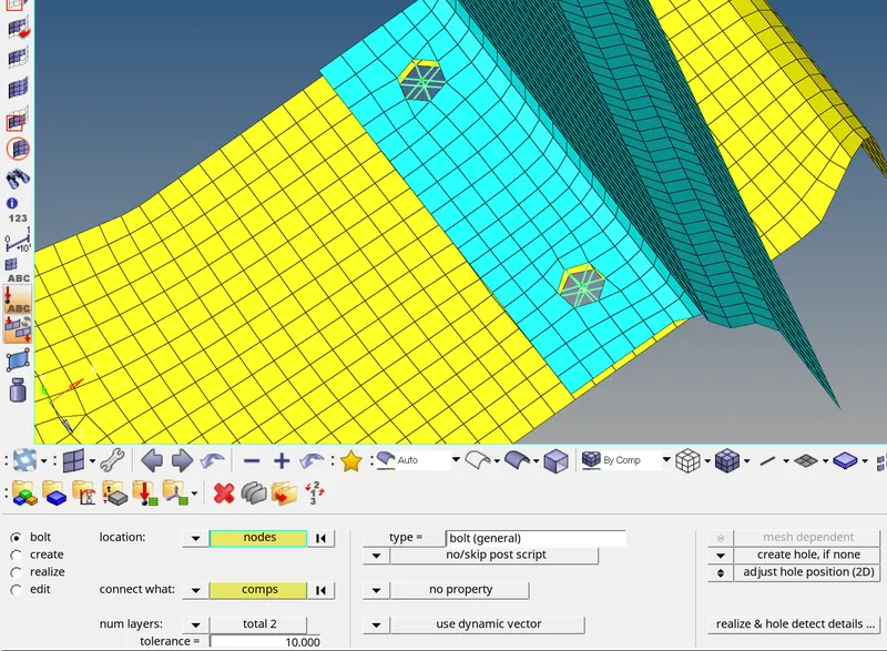
STEP 2E : Creation of bolt connection between rear_truss_2 and right_rail_2
- Now click on the 1D/2D → Connectors → Bolt option.
- Under “location”, select the node, to establish the bolt connection.
- Then selected the “comps” is rear_truss_2 and right_rail_2 option under “connect what”, in order to create the weld between those two components.
- Selected the number of layers is 2 to be welded, under “num layers” option.
- Specified the “tolerance” valueis 10 based on the distance between the two components.
- Selected the type as “bolt (general)”and selected create hole if none option.
- Click on the “create” button, created the Bolt Connection.
Bolt connection between rear_truss_2 and right_rail_2
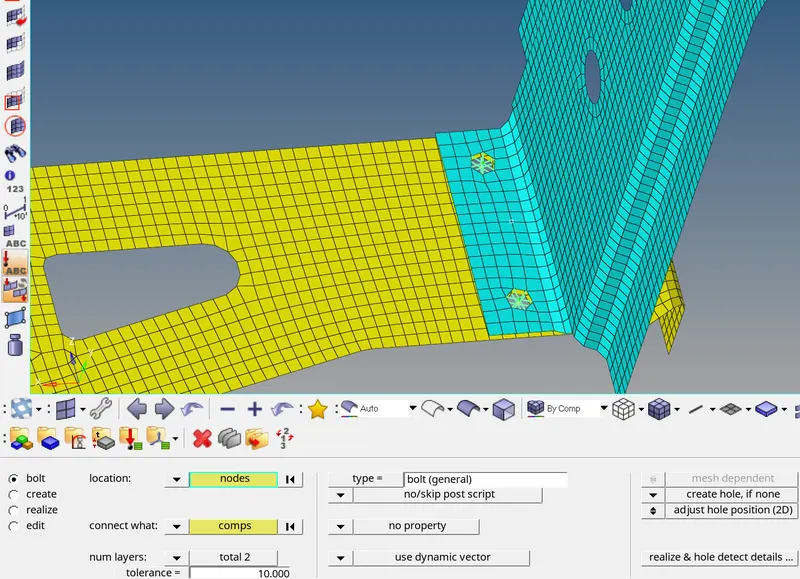
STEP 2F : Creation of bolt connection between rear_truss_2 and left_rail_2
- Now click on the 1D/2D → Connectors → Bolt option.
- Under “location”, select the node, to establish the bolt connection.
- Then selected the “comps” is rear_truss_2 and left_rail_2 option under “connect what”, in order to create the weld between those two components.
- Selected the number of layers is 2 to be welded, under “num layers” option.
- Specified the “tolerance” valueis 10 based on the distance between the two components.
- Selected the type as “bolt (general)”and selected create hole if none option.
- Click on the “create” button, created the Bolt Connection.
Bolt connection between rear_truss_2 and left_rail_2
STEP 2F : Creation of spot weld with rigid elements connection between right_rail_1 and right_rail_2
- Selected 1D/2D → Connectors → Spot option.
- Now selected the location, where the Weld has to be created, by clicking the “node list”.
- Selected the “comps” is right rail 1 and right rail 2 option under “connect what”, in order to create the weld between those two components.
- Selected the number of layer is 2 nos to be welded, under “num layers” option.
- Specified the “tolerance” valueis 5 based on the distance between the two components.
- Specified the diameter is 5 mm as per the given data.
- Selected the type as “rigid”.
- Click on the “create” button, created the spot weld with rigid elements.
Spot weld with rigid elements connection between right_rail_1 and right_rail_2
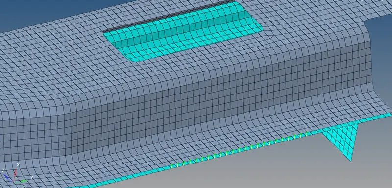
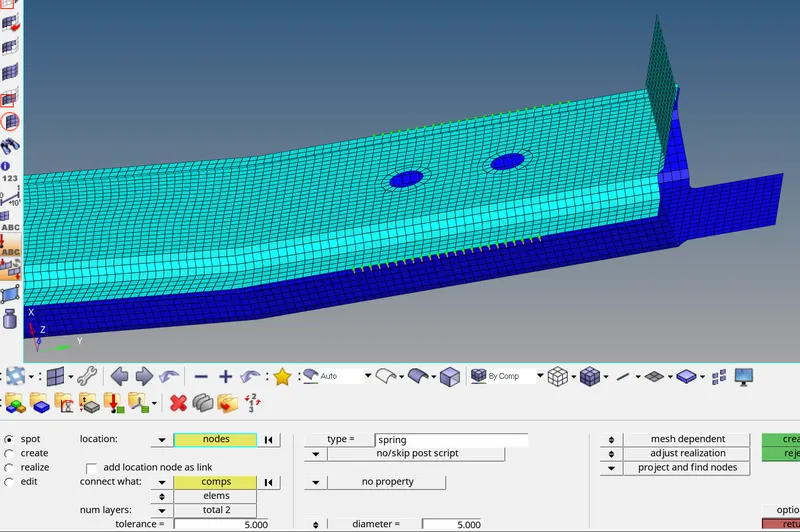
STEP 2G : Creation of spot weld with spring elements connection between left_rail_1 and left_rail_2
- Selected 1D/2D → Connectors → Spot option.
- Now selected the location, where the Weld has to be created, by clicking the “node list”.
- Selected the “comps” is left rail 1 and left rail 2 option under “connect what”, in order to create the weld between those two components.
- Selected the number of layer is 2 nos to be welded, under “num layers” option.
- Specified the “tolerance” valueis 5 based on the distance between the two components.
- Specified the diameter is 5 mm as per the given data.
- Selected the type as "spring”.
- Click on the “create” button, created the spot weld with spring elements.
Spot weld with spring elements connection between left_rail_1 and left_rail_2
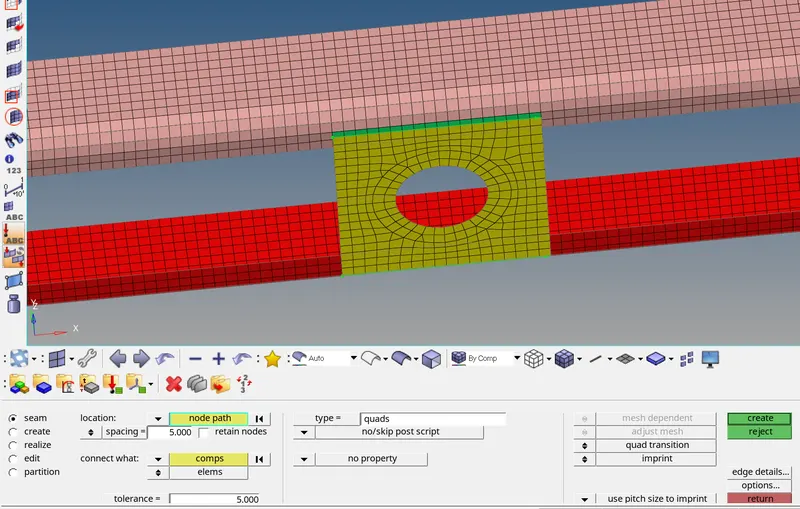
STEP 2H : Creation of Seam(quad elements ) weld connection between reinforcement plate , front_truss _1 and front_truss_2
1. Selected1D/2D → Connectors → Seam option.
2. Now selected the location, where the Weld has to be created, by clicking the “node list”.
3. Ticked the checkbox of “retain nodes” option, to retain the position of the nodes, while creating and realizing a
connector.
4. Specified the “spacing” value is 5 which is equal to target element length and selected the “comps” is reinforcement plate , front_truss _1 option under “connect what”, in order to create the weld
between those two components.
5. Specified the “tolerance” value is 5 based on the distance between the two components.
6. Selected the type as “seam(quad elements)”.
7. Clicked on the “create” button, the seam weld created.
Seam(quad elements ) weld connection between reinforcement plate , front_truss _1 & 2
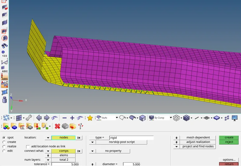
STEP 2I : Creation of spot weld with rigid elements connection between rear_truss_1 and rear_truss_2
- Selected 1D/2D → Connectors → Spot option.
- Now selected the location, where the Weld has to be created, by clicking the “node list”.
- Selected the “comps” is rear truss 1 and rear truss 2 option under “connect what”, in order to create the weld between those two components.
- Selected the number of layer is 2 nos to be welded, under “num layers” option.
- Specified the “tolerance” valueis 5 based on the distance between the two components.
- Specified the diameter is 5 mm as per the given data.
- Selected the type as “rigid”.
- Click on the “create” button, created the spot weld with rigid elements.
Spot weld with rigid elements connection between rear_truss_1 and rear_truss_2
STEP 2J : Creation of seam hexa adhesive weld connection between (1)left rail_1 and rear truss_2
(2)right rail_1 and rear truss_2
- Selected 1D/2D → Connectors → Seam option.
- Now selected the location, where the Weld has to be created, by clicking the “node list”.
- Tick the checkbox of “retain nodes” option, to retain the position of the nodes, while creating and realizing a connector.
- Specified the “spacing” value is 5 and select the “comps” option under “connect what”, in order to create the weld between those two components.
- Specified the “tolerance” value is 5 , based on the distance between the two components.
- selected no of strip as 2 and coat as 2 and width is 1mm
- Selected the type as “hexa (adhesive)”.
- Click on the “create” button,created the seam weld connections.
Seam hexa adhesive weld connection between left rail_1 and rear truss_2
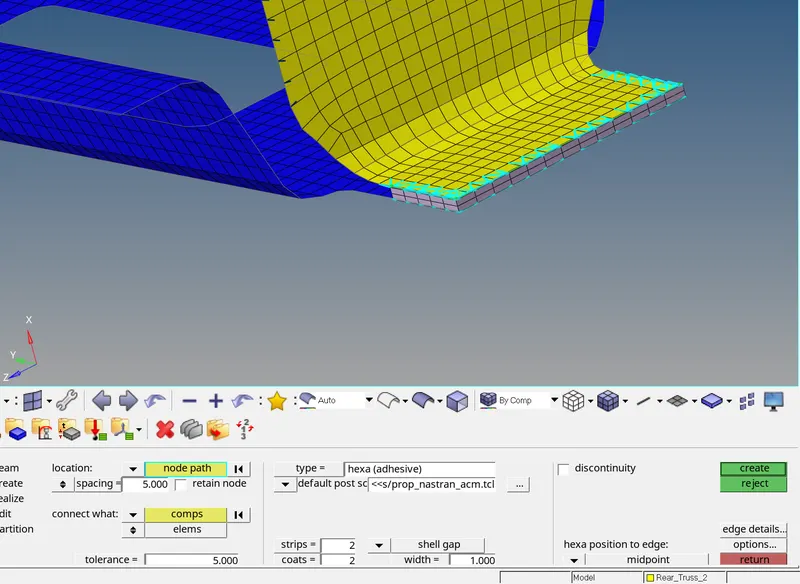
Seam hexa adhesive weld connection between right rail_1 and rear truss_2
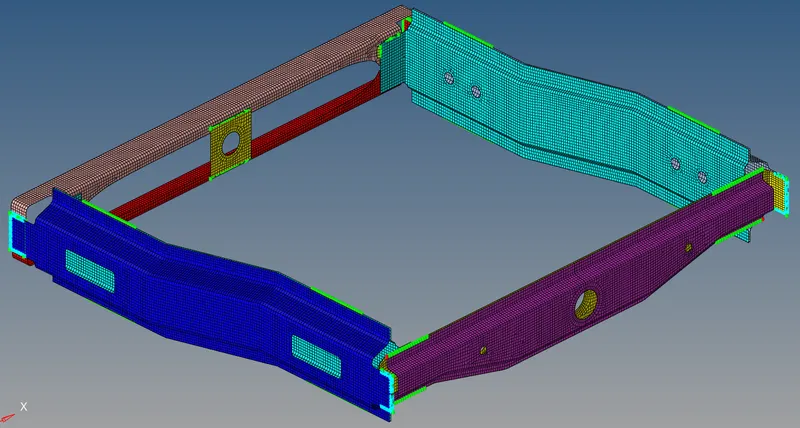
PERFORMED ALL REQUIRED CONNECTIONS IN THE OVERALL FRAME ASSEMBLY PARTS
RESULT:
- Performed 2D meshing on the frame assembly parts with no quality issues.
- Every components in the frame assembly to performed required connections have been defined
and sucessfully realized.
LEARNING OUTCOMES:
In this week 9 challenge, i came to know
- How to do uniform and proper mesh flow in 2D meshing process.
- How to do fix the elements which are failing for quality.
- how to create the following connections between the parts of an assembly
- Seam-quad ( angled + capped + L ) weld connection .
- Seam(quad elements ) weld connection.
- Seam( hexa adhesive weld connection .
- Spot weld connection.
- Spot weld with rigid elements.
- Spot weld with spring elements.
- Bolt connection.
4. How to do fix the failed connection.
5. How to do realize the connection between the parts.