Project 1 - 2D meshing on the instrumental Panel
2D MESHING OF AN AUTOMOTIVE INSTRUMENTAL PANEL
AIM :
- To perform mid surface extraction and 2D meshing on the automotive instrument panel according to the given quality criteria.
OBJECTIVE :
- To do geometric cleanup on the component.
- To generate a mid surface from the parent component.
- To Mesh the component according to the given quality criteria.
SOFTWARE USED :
Preprocessing software - ANSA V 22.1.1.
DATA BASE:
|
S.No |
Quality Criteria |
Value |
|
1 |
Target/Average length |
4 |
|
2 |
Minimum Length |
2 |
|
3 |
Maximum Length |
6 |
|
4 |
Aspect |
3 |
|
5 |
Warpage |
15 |
|
6 |
Skewness |
45 |
|
7 |
Jacobian |
0.7 |
|
8 |
Minimum Quad Angle |
45 |
|
9 |
Maximum Quad Angle |
135 |
|
10 |
Minimum Tria Angle |
30 |
|
11 |
Maximum Tria Angle |
120 |
|
10 |
Tria Percentage |
15 |
THEORETICAL VIEW:
Automotive instrumental panel
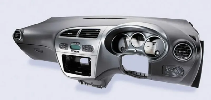
Eg: Mahindra Xylo DD2 - Instrumental panel and its parts
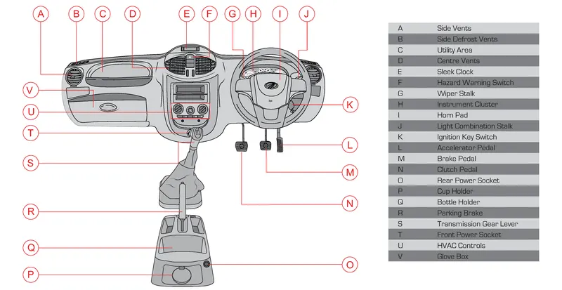
INSTRUMENTAL PANEL :
- The instrument panel of a vehicle is the panel where the dials and switches are located.
- The trip computer readout is mounted on the instrument panel of the car.
- The instrument panel is a cluster of gauges and switches that is mounted on the driver's side of the dashboard.
INSTRUMENTAL PANEL PARTS :
Instrumental panel contains the following parts,
- Speedometer tells you the speed of your vehicle in MPH and KPH.
- Tachometer shows how many rotations your engine is making per minute.
- Odometer shows how many miles your car has traveled in its lifetime.
- Fuel Gauge shows how much fuel remains in your car's tank.
- Gear Display shows which gear your car is currently in.
- Turn Signal Indicators flash when your turn signals are on; both will flash if you turn on your hazard lights.
- Active System Lights alert you to parts of the vehicle that are activated, such as an open trunk or door.
CAR DASHBOARD WARNING LIGHTS AND VEHICLE WARNING INDICATORS:
|
Temperature Warning Light: |
|
|
Oil Pressure Warning Light: |
|
|
Check Engine Warning Light: |
|
|
Tire Pressure Warning Light: |
|
|
Brake System Warning Light: If you do not have your parking brake on, your vehicle's brake fluid is okay, and your brake system Warning Light still comes on, you need to stop driving the vehicle and take the vehicle to a mechanic for repairing the brake system. |
|
|
ABS Warning Light: If both the Brake System Warning Light and ABS Warning Light come on while you're driving, pull over immediately – there is a possibility that your brake system is not working. Take your vehicle to a mechanic. |
|
|
Electronic Stability Control Light: |
|
|
Transmission Temperature Warning Light: |
|
|
Battery Warning Light: |
|
|
Airbag Warning Light: |
|
|
Door Ajar Warning Light: |
|
|
Fog Lamp: |
PROCEDURAL STEPS :
STEP 1 : Importing the cad model of an ANSA file of automotive instrumental panel .
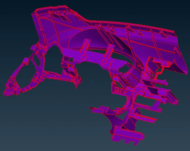
STEP 2 : Increase the Cons resolution by MESH MODULE > PERIMETER > LENGTH =1mm
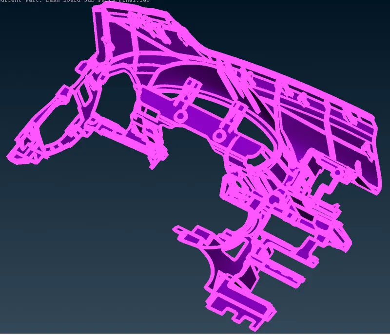
STEP 3 : To get the connectivity between the surfaces , performed TOPO by TOPO MODULE > FACES > TOPO .
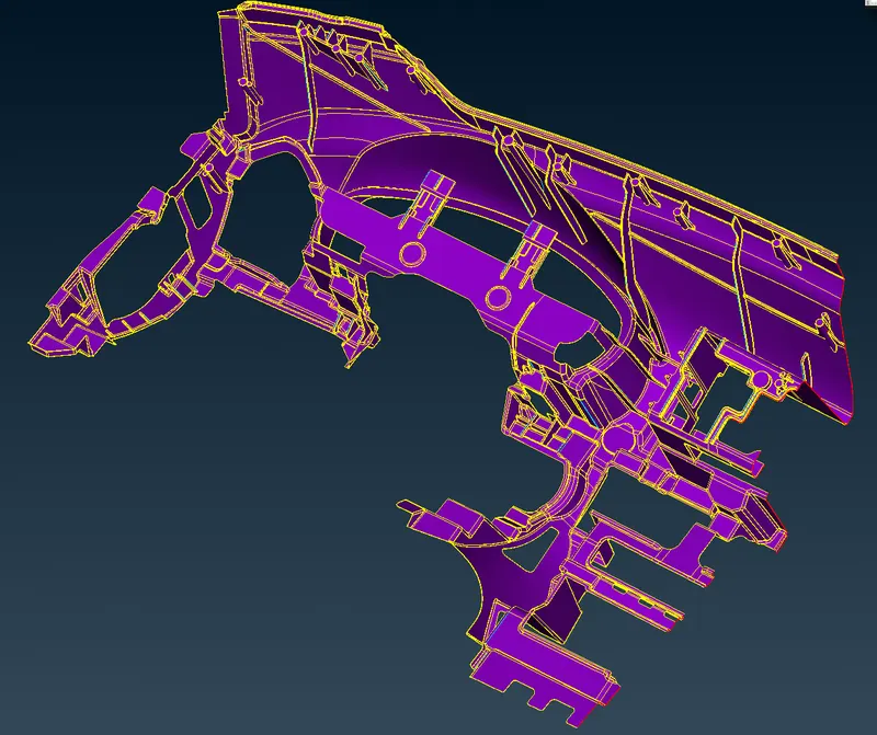
STEP 4 : Oriented the surfaces to make sure all the surfaces are in one normal direction.
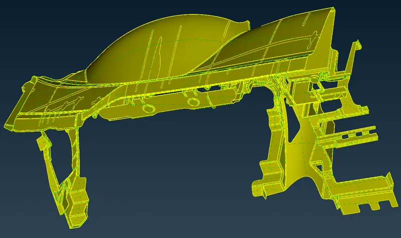
STEP 5 : Checked the geometrical errors and fixed those errors.
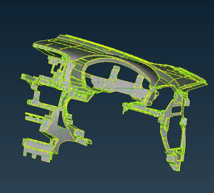
STEP 6 : Provided the Target element length by MESH MODULE > PERIMETER > LENGTH =4 mm.
Then performed the orientation Done.
STEP 7: Measured the thickness of the instrumental panel.
Thickness of the panel is 0.60 mm to all parts.
So casting midsurface generation method followed.
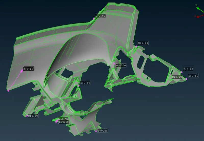
STEP 8 : Thickness is uniform, so the extraction of the middle mesh generation using casting method .
Before do the casting method , set the mesh parameter and quality criteria as per the given data base.
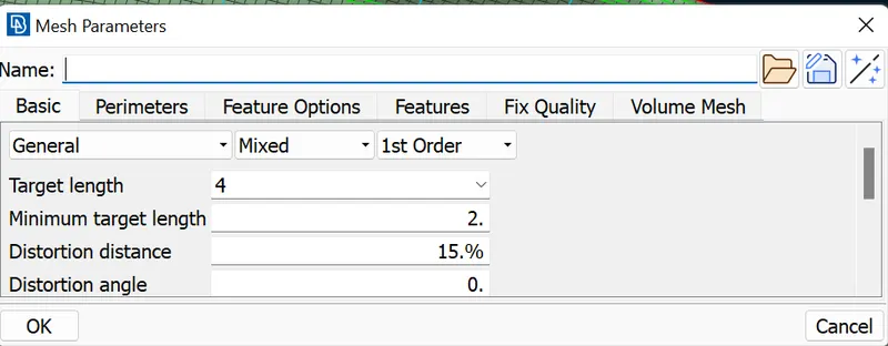
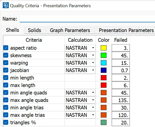
STEP 9 : Extraction of the middle mesh generation using casting method.
TOPO MODULE > FACES > MIDSURFACE > CASTING
In options disabled the geometrical errors.
Middle mesh generation is done.
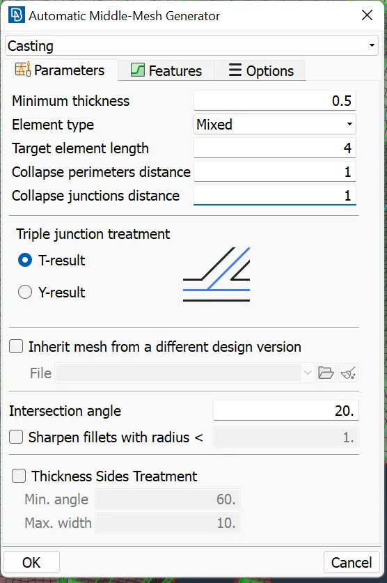
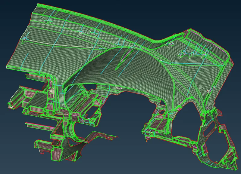
STEP 9A : To correct the areas and perimeters in Align manager .
TOPO MODULE > FACES > MIDSURFACE > ALIGN MANAGER - to corrected or fixed the empty areas and perimeters.
In align manager - checks the elements are properly correct or not and keep the elements are in middle.
STEP 10 : In Align Manager , first of all fixed the empty typed areas and empty typed perimeters.
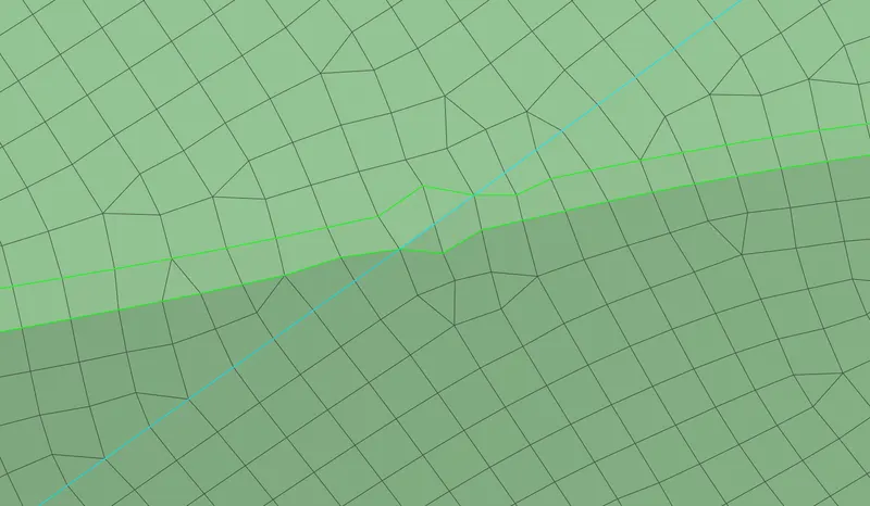
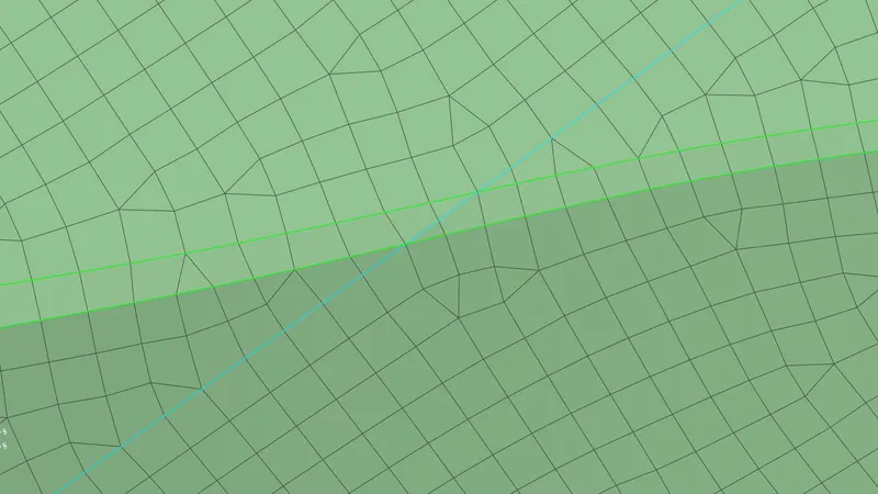
STEP 10 A : Align the construction line / perimeter line.
Align Manager > perimeter > selected the perimeter line need to be align.
Then go to offset > right click > align
process Done .
Then the zig zag line alligned to the straight line.
Before disalligned perimeter line ( green )
After disalligned perimeter line
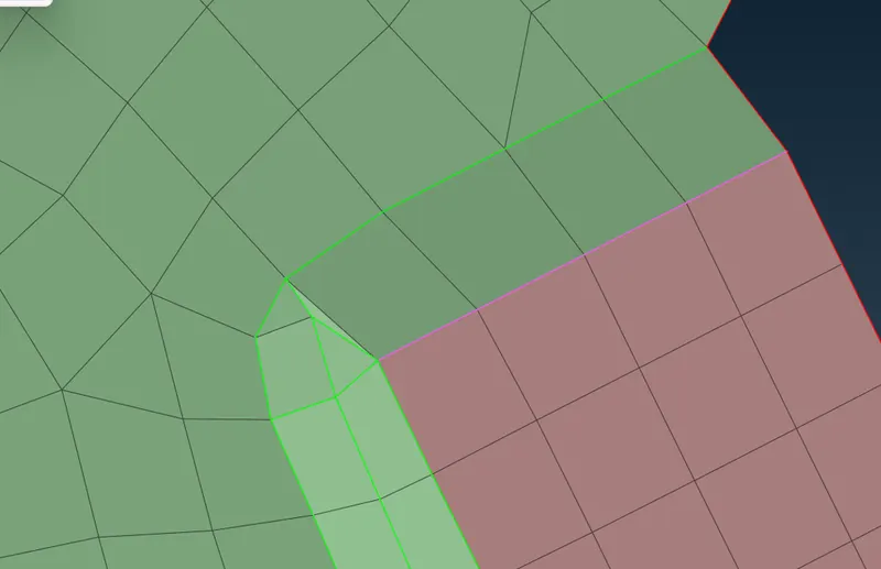
STEP 10 B : Merging the FE Area
Align Manager > Plane > R.C > Merge > Selected the areas needs to be merge
( or )
CLASSIC MESH > MACROS JOIN > selected the line which is merged to the two areas.
Before merging the FE area

After merging the FE area
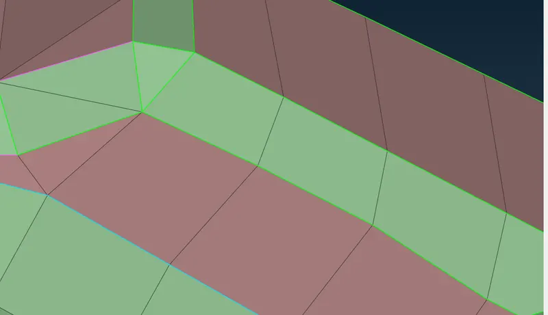
STEP 10 BB: Providing the definition of curved FE
In Align Manager > Areas > empty ( Selected the curved FE) > R.C > Middle > selected 2 Group of faces > finish.
Before Empty Curved FE
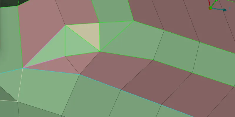
After Fixed the Empty curved FE
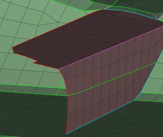
STEP 10 C : Providing the definition of Flat FE.
In Align Manager > Areas > empty ( Selected the flat FE) > R.C > Plane > selected 2 Group of faces > finish.
Before Empty Flat FE
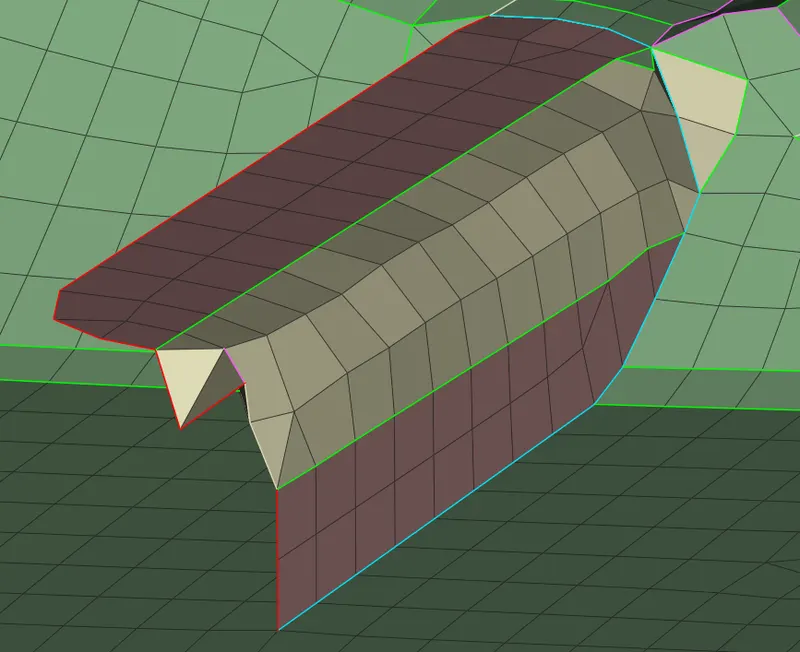
After fixed the Empty Flat FE
STEP 10 D : Fixed the sharp perimeter.
align manager > imprint -the selected edge > Direct option.
(or)
Classic mesh > macros > join > the selected pink color edge
Before fix the sharp edge
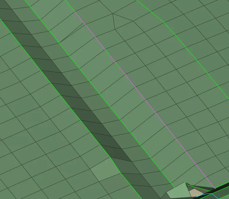
After fixed the sharp edge
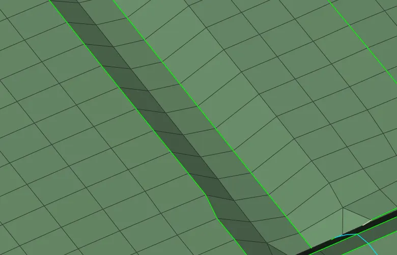
STEP 10 D : Fixed the Collapsed dog houses and long Ribs.
1. Deleted the collapsed dog house FE areas and Collapsed curved or flat areas.
2. MESH MODULE > SHELL MESH > FILL - Selected the deleted areas needs to be filled.
3. In dog house captured the cylindrical FE area by using TOPO MODULE > CURVES > MIDDLE > selected the 2 cons- created curve.
4. Then projected the curve into the base, by MESH MODULE > SHELL MESH >PROJECT > MANUAL- selected the perimeter/ curves nneds to newly created FE.
5. Then go with MESH MODULE > SHELL MESH > FILL - selected the curves and projected line.
6. Newl FE area Created .
7. Then provided the definition of the newly Created FE by,
8. In Align Manager > Areas > empty ( Selected the curved FE) > R.C > Middle > selected 2 Group of faces > finish.
9. In Align Manager > Areas > empty ( Selected the flat FE) > R.C > Plane > selected 2 Group of faces > finish.
10. Empty perimeters are created during newly created FE Area.
11. Empty perimeter fixed by,
Align Manager > perimeter > empty perimeter line > R.C > New > selected the faces . its fixed show as red line.
12. Disaligment of the FE areas fixed by,
Align Manager > Areas > Selected the FE area > R.C > Align - selected areas needs to be aligned.
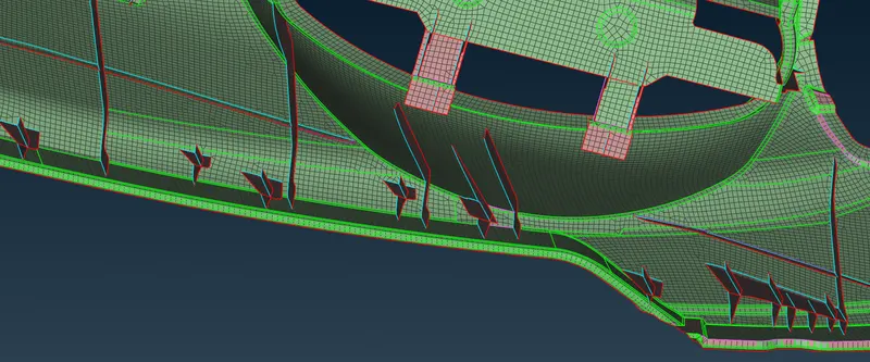
Collapsed dog houses and ribs
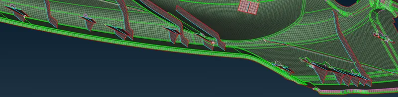
After Fixed the new dog houses and ribs
STEP 10 E : Feature Discontiniuty.
Macros > Cut
Macros > join (merge / keep bigger )
STEP 10 F : Correct Definition faces.
Align Manager > areas > RMB > Add to the near area
Align Manager > Direct > Drag and drop of the selected Nodes.
STEP 10 G : Deleted unwanted nodes.
STEP 10 H : Edit definition faces
Align Manager > areas > RMB > Edited the selected areas.
STEP 10 I : Remove unnecessary Macros.
Macrios > Join ( Keep bigger )
STEP 10 J : Correct fillets.
Align manager > Direct > LMB
STEP 10 k : Correct fillet boundaries
Hot points > Delete (keep bigger )
STEP 10 L : Correct perimeter.
Align manager > Perimeter > RMB > new > points- selected the adjacent points.
STEP 10 M : Collapsed perimeter.
Align manager > Direct > Drag and Drop the 1st point to 2nd point.
STEP 10 N : Edit the feature boundaries.
Align manager > imprint.
STEP 10 O : Detach feature .
Macros > cut
Macros > join.
STEP 10 P : Correct intersecting Areas.
Align manager > areas >RMB > Change the angle.
STEP 10 Q : Mesh Discontnuity.
Align manager > Direct > Drag and Drop.
Grids > Paste.
STEP 11 : Align constraints.
When some modification required according to the align constraints,
Align manager > Option > check cliick all ,then do the align sonstraints.
When some modifications are not required according to the align constraints,
Align manager > Option >check unclick all ,Except draw constraint definition selected -then do the Macros cut ,Mesh Reconstruction and proper mesh flow.
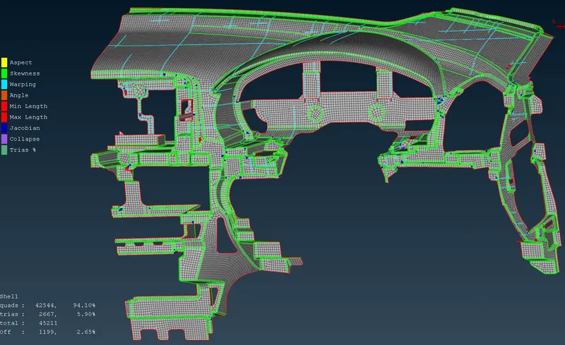
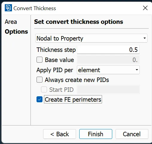
STEP 12 : Thickness Conversion.
MESH MODULE > GRIDS > THICKNESS > CONVERT >selected the whole shells.
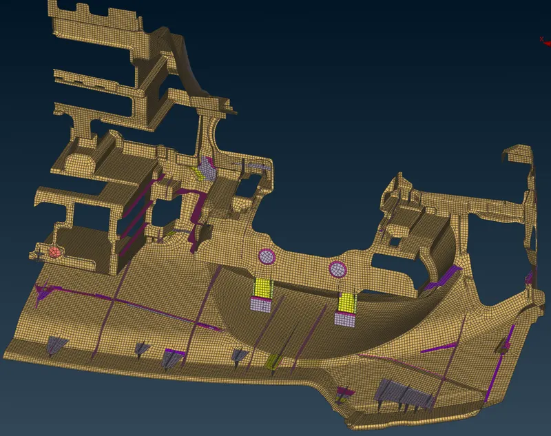
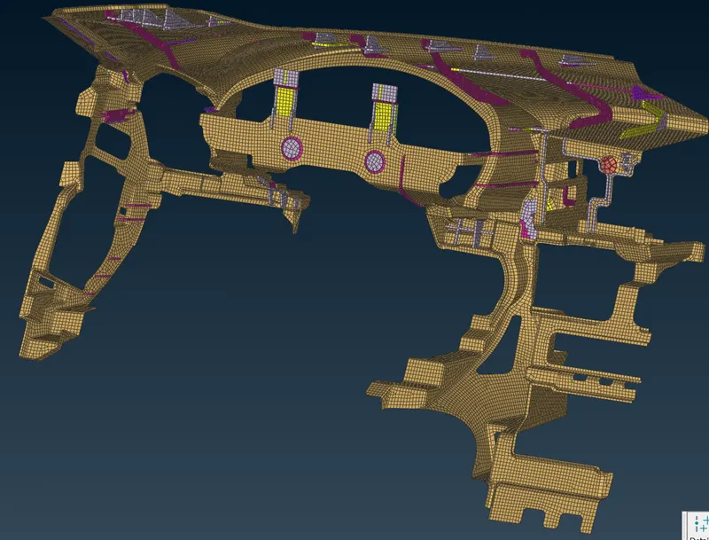
2D meshing of an instrumental panel
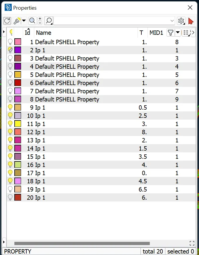
STEP 13 : Set PIDs
Set PIDs at the elements PIDs.
STEP 14 : Orientation check.
Oriented the surfaces to make sure all the surfaces are in one normal direction.
TOPO MODULE > FACES > Orient - selected the all faces.
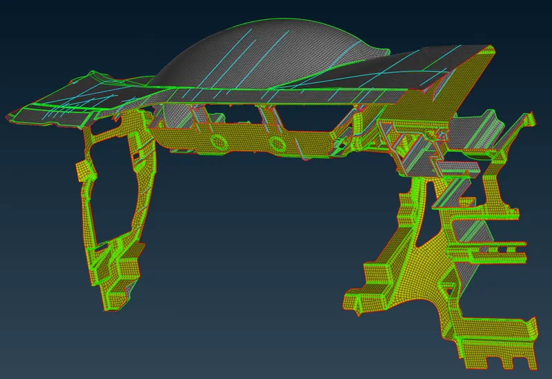
STEP 12 : Draw shell as a solid .
1. To convert 2D into 3D of an instrumental panel.
RESULT :
1. Hence the middle mesh has been extracted to the parent component.
2. Hence there are no surface deformations in the geometry.
3. A well connectivity has been established between the surfaces.
4. The features have been captured properly.
5. A good mesh flow have been achieved.
6. In align manager used to keep the elements are in middle and the elements are properly corrected.
CONCLUSION :
In this project 1,I came to know
1. How to extract the mid mesh generation by casting method for complex components
2. How to clean complex geometry. 3. How to Edit areas and perimeters in alignn manager
4. How to generate a proper mesh flow with low tria percentage.
5. How to generate newly created doghouse FE .
6. How to set PIDs to the element PIDs.