Week 4-1D Element Creation Challenge
ONE DIMENSIONAL ELEMENT CREATION IN AN PARALLEL BRACKET
OBJECTIVE :
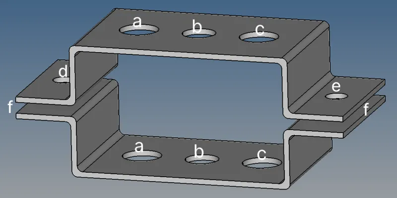
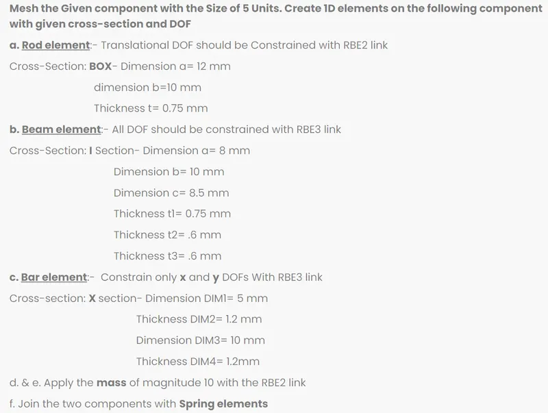
- To mesh the parallel bracket with the size of 5 units.
- To create 1D elements such as Bar, Rod and Beam in the parallel bracket with given cross section and DOF.
- To apply the mass of the magnitude.
- To join the two components with spring elements.
DATA BASE :
SOFTWARE USED :
Preprocessing software - Hyperworks Desktop 2022
PROCEDURAL STEPS :
PART 1 : MESHING OF AN PARALLEL BRACKET
STEP 1A : IMPORT THE MODEL
» Imported the .IGS file of parallel bracket in Hyperworks.
» File > import > Geometry > select IGS file of bracket , then imported it.
CAD model of an parallel Bracket
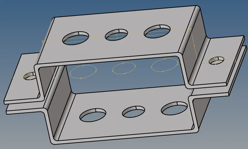
STEP 1B : EXTRACT MIDSURAFCE OF AN MODEL.
» In main menu page selected the Geometry option , then slected the midsurface tool.
Main menu page > Geomtery > midsurface > select the surface of the one part of the bracket.
> automidsurface > then extracted theMidsurafce.
» Model tree > selected the extracted midsurface renamed as a bracket _1 and change the color also.
Midsurface created on the Bracket_1
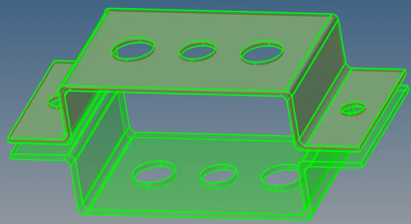
» Model tree > selected the Component options right click to create new component renamed as bracket_2 and change
the color also.
» Main menu page > Geomtery > midsurface > select the surface of the bracket _2.
> automidsurface > then extracted the Midsurface .
Midsurface created on the Bracket_2
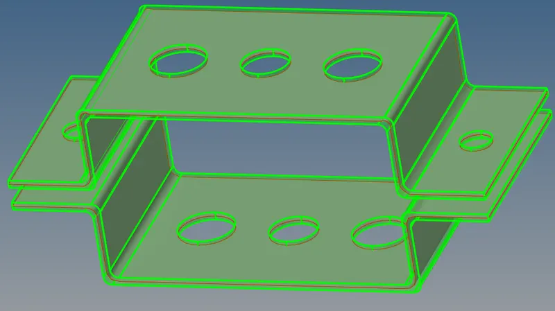
» then deleted the solids by Delete option > select solid > delete entity .
and also deleted the bracket solids in model tress > componenet > selected the two solid body of an bracket.
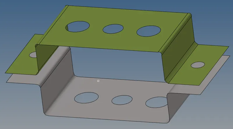
» lets move the midsurface to the bracket_2
Mainmenu > tool > organize > click collectors and set the destination component as bracket_2
then selected the midsurafce of an bracket_2. Then moved it.
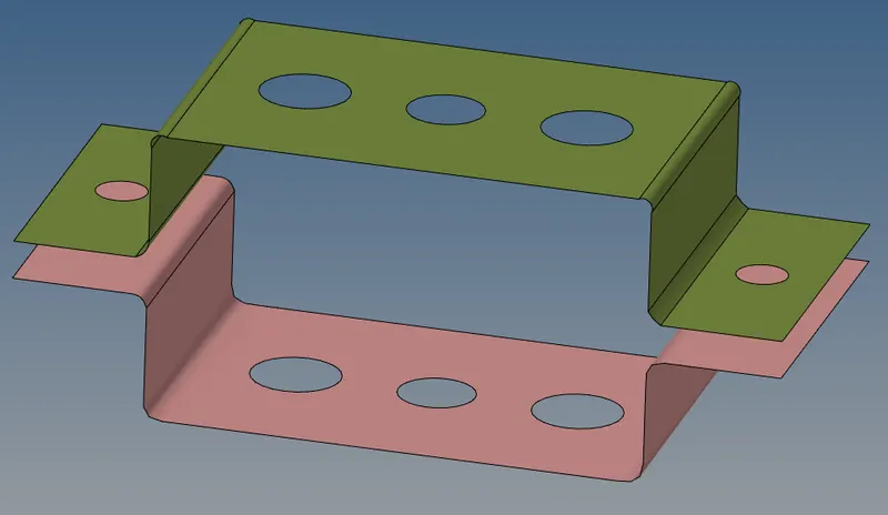
» Then deleted the midsurface in componenet options iof the model tree.
Midsurafces of the bracket_1 & bracket_2
STEP 1C : ASSIGNING MATERIALS AND PROPERTIES TO THE MIDSURFACE OF AN PARALLEL BRACKET.
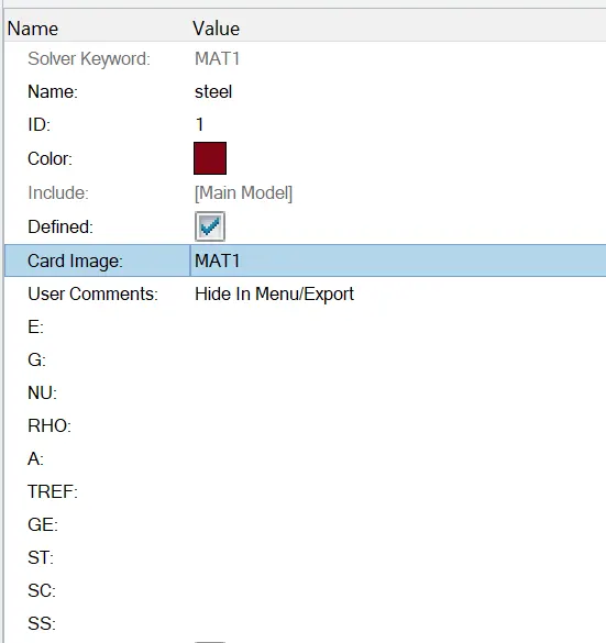
» In model tree do right click to create material named as steel.
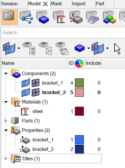
» Then created two new properties for 2 parallel brackets in model tree.because it has 2 different thickness.
Created properties of the bracket_1& bracket_2
» Now do to assigning newly created properties to the midsurface.
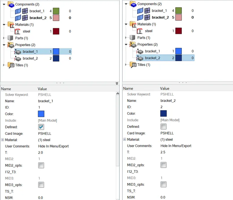
» Set the thickness value of the bracket_1 = 2 mm and card image as PSHELL in bracket_1 property in model tree.
Same as set set the thickness value of the bracket_2 = 2.5 mm and card image as PSHELL in bracket_2 property.
Set the thickness and card image as properties of bracket_1& bracket_2
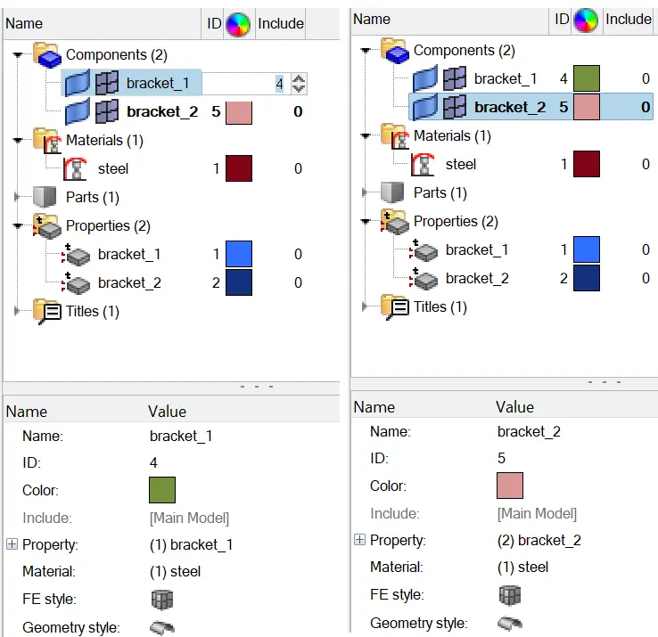
» Then go to the componenets in model tree selected the bracket_1 component to set the assigned the bracket _1 property.
Same as selected the bracket_2 component to set the assigned the bracket _2 property.
Assigned the bracket_1 &bracket_2 properties
STEP 1D : AUTOMESHING OF AN PARALLEL BRACKET.
STEP 1D1 : AUTOCLEANUP OF THE MIDSURFACES OF AN PARALLEL BRACKET.
» Before go the meshing process, lets do the autocleanup of the midsurafces.
» By using "autocleanup option " to allows clean up the midsurface by its merging vertices which are very close
to each other into a single vertex and then its automatically creates the washer splits.
» Before, execute into autoclean, have to edit the "edit criteria' and "edit parameter" for changing a some meshing
target element size.
» Main menu > Geometry > Autocleanup > edit criteria - to set target element size = 5 units.
Main menu > Geometry > Autocleanup > edit parameter > basic > mesh options > target element size = 5 units.
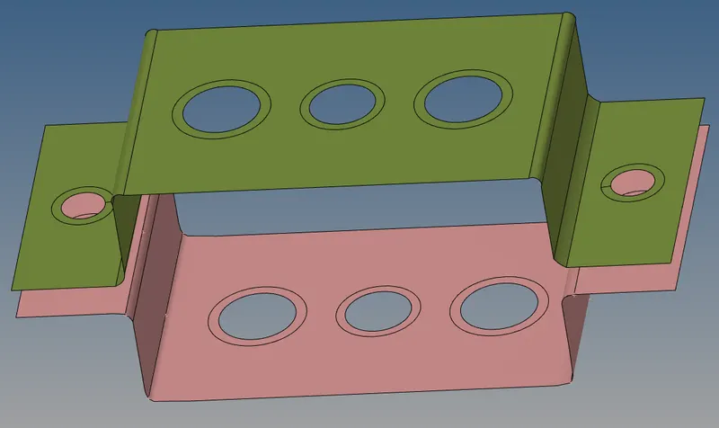
Washer split created after autocleanup
STEP 1D2 : AUTOMESH OF THE MIDSURFACE OF AN PARALLEL BRACKET.
» Mainmenu > 2D > automesh > slected the all surfaces by surface displayed option
» Set the target element size = 5 units ,and mesh type = mixed.
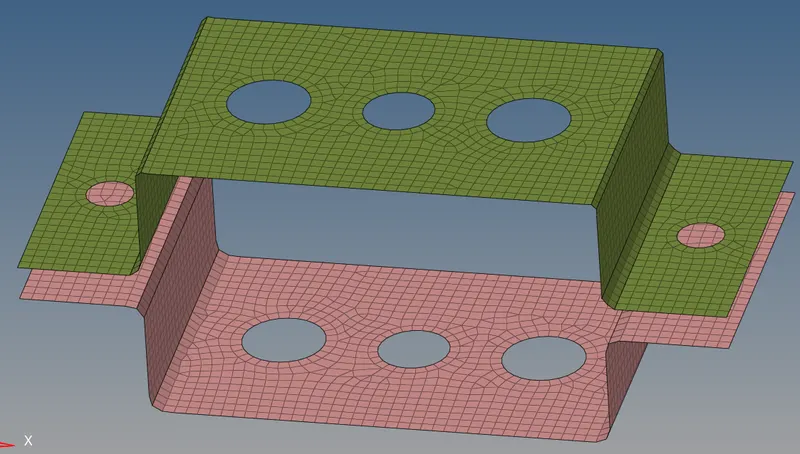
» Proper mesh flow was achieved near washer split.
Proper meshflow of an parallel bracket
PART 2 : 1D ELEMENT CREATION IN THE FE OF AN PARALLEL BRACKET.
STEP 2 : Creation of rod element between bracket1 [a] hole and bracket2 [a] hole.
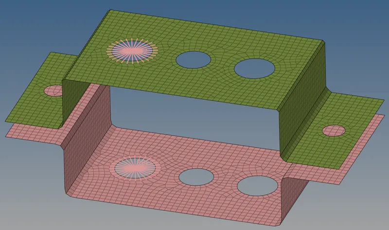
» Firstly creation of RBE2 cluster links in bracket 1 [a] hole and bracket 2 [a] hole.
» Mainmenu 1D > rigids > independent (Calculate node) > dependent (Multiple node) > by paths > select
Translational dof 1, dof 2, dof3 > Create.
» Cluster RBE2 links created in bracket 1 [a] hole and bracket 2 [a] hole with Translational DOF only.
Cluster RBE2 links created between parallel brackets
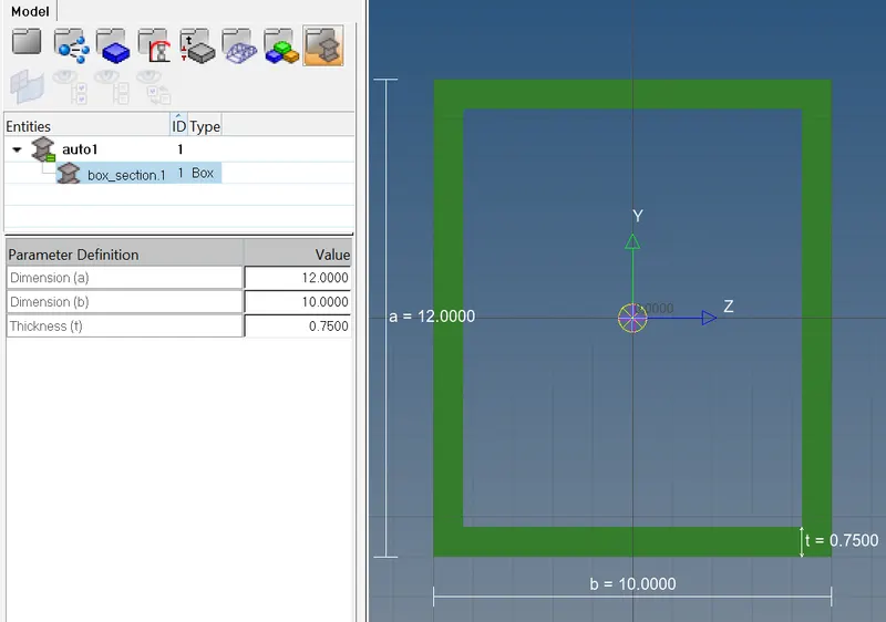
» Now to create Rod we have to follow some steps.
» 1D > Hyper beam > standard section > thinwalled box > create > Assign with given dimensions also renamed as Rod.
Assigned the cross section of the ROD
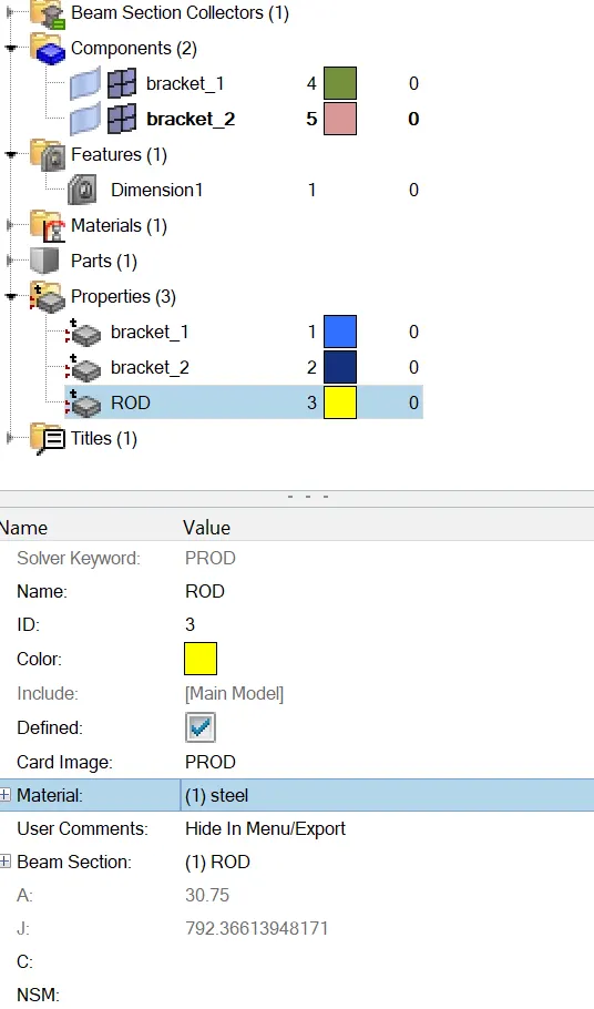
» Now to apply property for the rod.
» Go to model tree > Right click > property > Rename to ROD > Change card image to PROD >
& change Material to Steel > BEAM Section > ROD
Applied Properties to the ROD
» Now for creating ROD location we have to follow some steps.
1D > Rods >select bracket1 node and bracket2 node in the holes[a]. > Element type CROD > Created it.
Created ROD location between parallel bracket
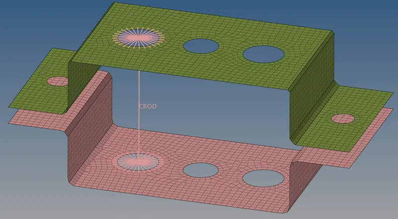
» Now update the 1D element.
1D > rods > update > property = ROD > update.

» To see the ROD we have to go 1D Detailed Element Representation.
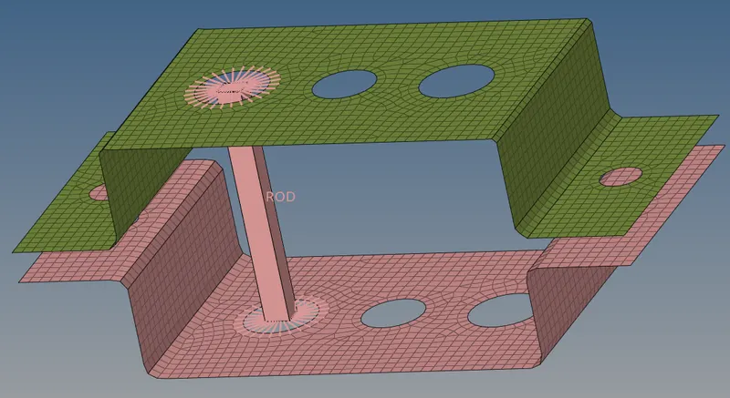
STEP 3 : Creation of beam element between bracket1 [b] hole and bracket2 [b] hole.
» Firstly creation of RBE3 cluster links in bracket 1 [b] hole and bracket 2 [b] hole.
» Mainmenu 1D > rigids > independent (Calculate node) > dependent (Multiple node) > by paths > select
Translational dof1, dof2, dof3 and rotational dof4,dof5 ,dof 6 > Create.
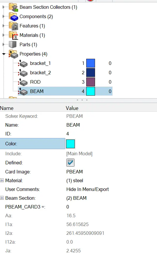
» Cluster RBE3 links created in bracket 1 [a] hole and bracket 2 [a] hole with rotational and translational DOF.
Cluster RBE3 links created between parallel brackets
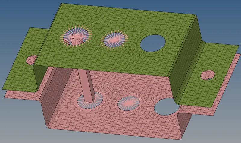
» Now to create beam we have to follow some steps.
» 1D > Hyper beam > standard section >standard I section > Create > Assigned with given dimensions and Renamed as a Beam.
Assigned the cross section of the BEAM
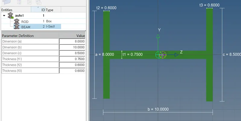
» Now to apply property for the beam.
» Go to model tree > Right click > property > Rename to BEAM > Change card image to PBEAM
> change Material to Steel > BEAM Section > BEAM.
Applied Properties to the BEAM
» Now give location for BEAM.
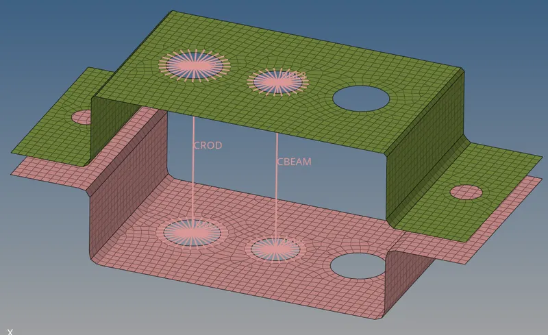
» 1D > Rods >selected bracket1 node in the hole[b] and bracket2 node in the hole[b] > Element type CBEAM.
Created BEAM location between parallel bracket
» Now update the 1D element.
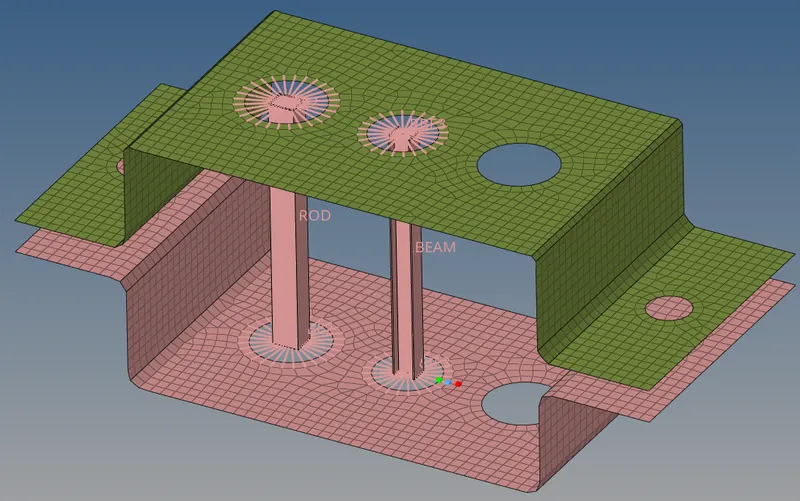
» 1D > rods > update > property = BEAM
> BEAM Section > BEAM.
> Element type =CBEAM.
» To see the BEAM we have to go 1D Detailed Element Representation
STEP 4 : Creation of ROD element between bracket1 [C] hole and bracket2 [C] hole.
» Firstly creation of RBE3 cluster links in bracket 1 [a] hole and bracket 2 [a] hole.
» Mainmenu 1D > RBE3 > independent (Calculate node) > dependent (Multiple node) > by paths > selected
Translational dof 1, dof 2 and rotational dof 4, dof5 > Create.
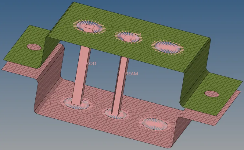
» Cluster RBE3 links created in bracket 1 [a] hole and bracket 2 [a] hole with translational X & Y DOF and rotational X &Y DOF.
Cluster RBE2 links created between parallel brackets
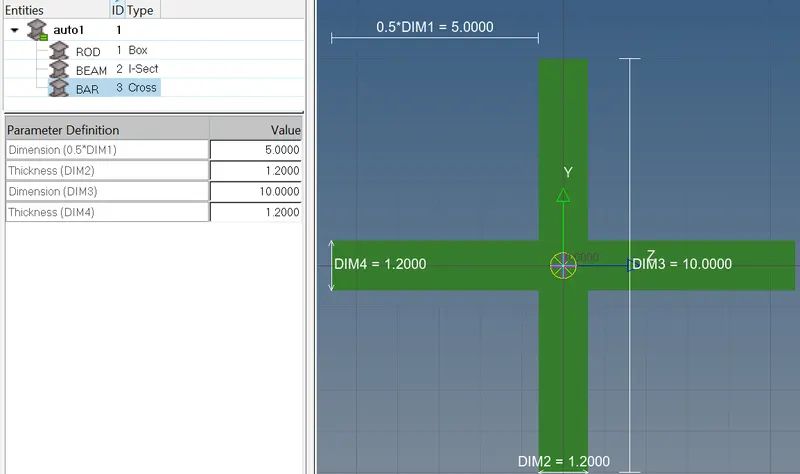
» Now to create Bar we have to follow some steps.
» 1D > Hyper beam > > Standard Section library (OPTISTRUCT) > Standard section type (CROSS) > Created it.
> Assigned with given dimensions and renamed as a BAR.
Assigned the cross section of the BAR
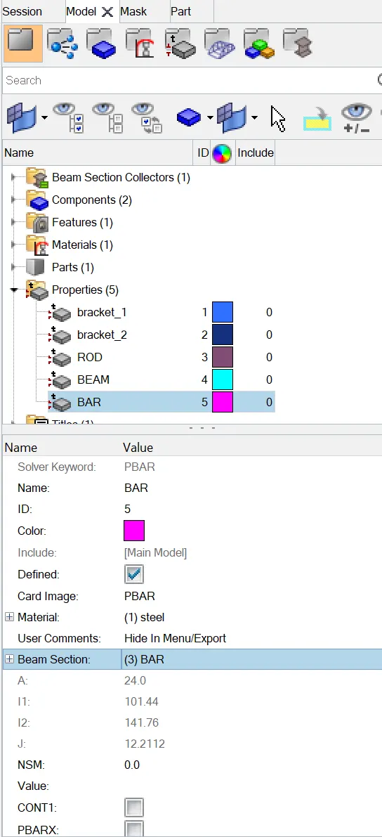
» Now to apply property for the BAR.
» Go to model tree > Right click > property > Rename to BAR > Change card image to PBAR
> change Material to Steel > BEAM Section > BAR.
Applied Properties to the BAR
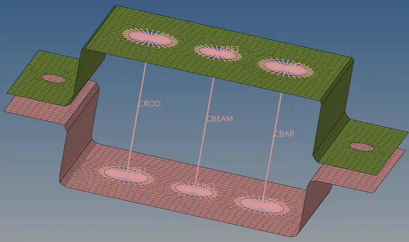
» Now give location for BAR.
» 1D > Bars >selected bracket1 node in the hole[b] and bracket2 node in the hole[b] > Element type CBAR.
Created BAR location between parallel bracket
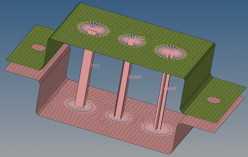
» Now update the 1D element.
» 1D > BARS > update > property = BAR.
> Element type =CBAR.
» To see the BAR we have to go 1D Detailed Element Representation.
STEP 5 : Apply the mass of magnitude in bracket1 [d,e] holes and bracket2 [d,e] holes.
» First of all creation of RBE2 links in bracket1 [d,e] holes and bracket2 [d,e] holes.
» Mainmenu >1D > rigids > independent (Calculate node) > dependent (Multiple node) > by paths >
selected all DOF > Create.
» Cluster RBE2 links created in bracket 1 [d,e] hole and bracket 2 [d,e] hole with all DOF.
» Mainmenu > 1D > masses > MASS = 10 > Element type (CMASS1) > Selected the RBE2 Links.
Applied mass of the magnitude between parallel brackets
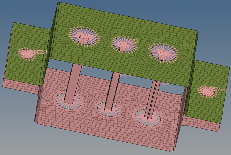
STEP 6 : Joining the bracket1 and bracket2 with spring element.
» Before that we will create REB2 cluster links in both side of gap F.
» Mainmenu >1D > Rigids > independent (Calculate node) > dependent (Multiple node) > by paths > Created it.
» To create Spring element on both side of gap F.
» 1D > springs > element type HMSPRING > Select the node both side of (F) > Spring is created.
Created spring element between the gaps of the parallel brackets
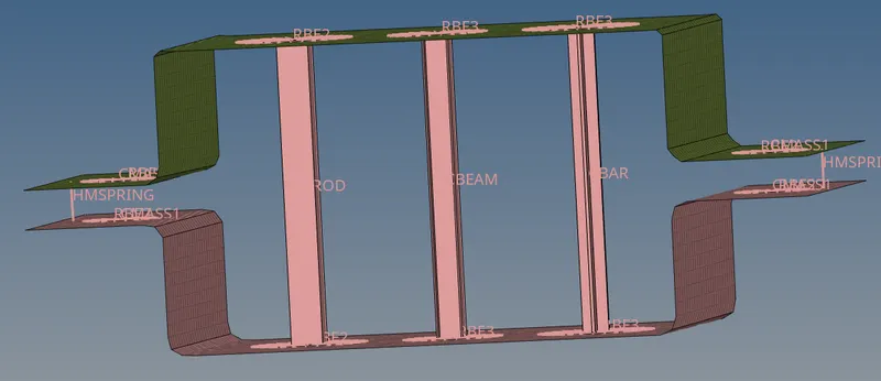
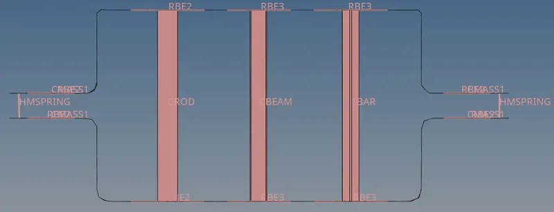
3Dimensional representations of the bracket with connections
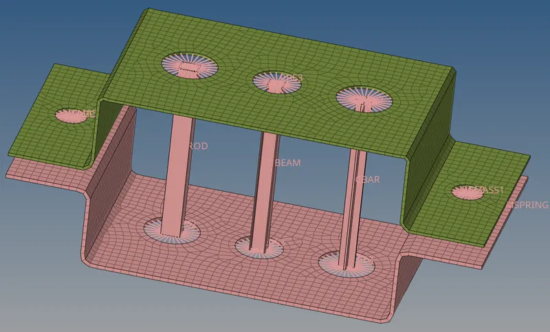
RESULT :
- ROD element as given dimension with RBE2 link created and Translational DOF constrained with RBE2 link successfully at A section
- BEAM element as given dimensionn with RBE3 link created and all DOF constrained with RBE3 link successfully at B section
- BAR element as given dimension with RBE2 link created and X and Y DOF constrained with RBE2 link successfully at C section
- Mass has been applied with magnitude of 10 successfully at D & E section.
- Joining the two components with spring elements created successfully at gap F