Week-7 Head Impact
PEDESTRIAN HEAD IMPACT SIMULATION
AIM:
- To simulate and comparison of the pedestrian head impact with rigid wall and pedestrian head impact with hood is solved by using Ls-dyna.
OBJECTIVE:
- To create a simple elastic material model for the simple head (meshed) that is provided.
- To calculate the HIC value of the pedestrian head impact with rigid wall.
- To calculate the HIC value of the pedestrian head impact with hood.
DATA BASE:
- These tests are usually done at a lower velocity from 20-40 kmph as accidents.
- The Impact angle of the Pedestrain Head is between 35-75 degrees.
ASSUMPTIONS :
- The bonnet should be considered as a rigidwall for the 1st case and for 2nd case while using the meshed hood model a elasto-plastic (aluminium) material card has to be used.
- The head impact coefficient must be calculated manually and with the help of LS-PrePost.
- Multi-include file model using the keywords *INCLUDE,*INCLUDE_TRANSFORM,*DEFINE_TRASFORMATION.
DELIVERABLES:
- The impact simulation of a simple head impact with the Rigid wall.
- The impact simulation of the Headform provided with the Rigid wall with the Stress / Strain plots and acceleration plot.
- The impact simulation of the head form with the Hood with the Stress / Strain plots and acceleration plot.
- The Stress / Strain plot from the Rigidwall simulation should be compared with the Stress / Strain plot from the Hood Simulation and there should be a detailed explanation if there is any difference in the plots.
SOFTWARE USED :
- Solver tool - LS-Prepost 4.7.17 and LS-Run 1.0.100838
BACKGROUND :
Pedestrain Head Impact
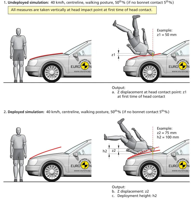
- Pedestrian protection CAE is a part of vehicle safety engineering from a crash perspective. In pedestrian protection, we look for imparting minimum injury to head, upper leg (thigh), and lower leg (including knee) in case of an accident with a human subject.
- About 14% of all road fatality in Europe are pedestrians, with children and the elderly being at the greatest risk. Pedestrian comprises one of the main categories of vulnerable road user which also include cyclist and motorcyclists.
- Most Pedestrian accidents occur within city areas where the speed are moderate. The head, the lower body and the legs are the most frequent injured body regions. To estimate the potential risk of Head injury in the event of Vehicle striking an adult or a child, a series of impact test is carried out at 40kmph using an adult r child Head form impactor. Impact sites are then assessed and the protection offered is rated as good, adequate, weak, marginal and poor.
- The procedure promotes energy absorbing structures, deformation clearance and deployable protection system such as popup bonnets and external airbags.
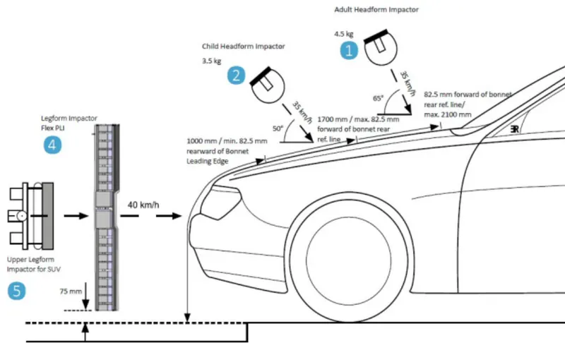
- The major source of child and adult pedestrian HEAD injuries is the top surface of the Bonnet of the striking vehicle. The Bonnet would be impacted with a head-form at 35 to 40kmph. The Bonnet would be divided into a “Child Head-from Test area and an “Adult Head-Form test area”. The child Head-Form test area is the area of the Bonnet that is likely to be impacted by the Head of a midsize adult male pedestrian is likely to impact. An adult head-form test area corresponds to the area of Bonnet that Head of a mid-size adult male pedestrian is likely to impact. An adult head-form is used to test the Bonnet I the latter area.
Child Head Impact:
- Car-Pedestrian accidents accounts for a considerable number of automobile accident in industrialized countries.
- Head injury continue to be more concern with Automobile impacts, because Head is the most seriously sensitive part and injured in many collisions including in pedestrian vehicle collision.
- To reduce the severity of such injuries international safety committee have proposed system test in which head-form impactor are impacted upon the car hood.
Head injury criteria (HIC)
- The head injury criterion (HIC) is a measure of the likelihood of head injury arising from an impact. ... At a HIC of 1000, there is an 18% probability of a severe head injury, a 55% probability of a serious injury and a 90% probability of a moderate head injury to the average adult.
- The head foam impactors are used to test the behavior on vehicle structures such as the hood. In a pedestrian-vehicle impact, the kinematics and severity of pedestrian injuries are affected by the impact locations on the vehicle and body velocities after impact. The objective of this project is to analyze the pedestrian kinematics in a Pedestrian-Car accident scenario and determine the Head Injury Criteria (HIC) from the head resultant acceleration, for head impacts on the vehicle hood.
- The equation used for the measurements of the head injury of the whole model for the pedestrian head impact was head injury criteria (HIC). It has been used to predict the risk of engine hood to a pedestrian during the collision.
- HIC is calculated according to the below Equation

Where
- a: the resultant acceleration (as a multiple of 10 ms-2 or about 1 g)
- t1, t2: two-time instants (in seconds)
Note :
For example, At HIC=650,
90% probability of level 1,
55% of level 2,
20% of level 3,
5% of level 4.
Abbreviated Injury Scale (AIS):
Level 1: Slight damage to the brain with headache, dizziness, no loss of consciousness, confusion.
Level 2: Concussion with or without skull fracture, less than 15 minutes of unconsciousness, detached retina, face, and nose fracture.
Level 3: Concussion with or without skull fracture for more than 15 minutes of unconsciousness without severe neurological damage, multiple skull fractures, loss of vision, multiple facial fractures, cervical fracture without damage to the spine.
Level 4: Multiple skull fractures with severe neurological damage.
Level 5 : concussion with or without skull fracture more than 12 hours of unconsciousness hemorraghe in skull and critical neurological condition.
Level 6 : Death cervical fracture with damaged to the spine.
PROCEDURAL STEPS :
CASE 1 : SIMPLE HEAD MODEL STRIKE AGAINST RIGID WALL.
STEP 1A : Import the file.
- Imported the K format type of file using LS-Prepost software.
- File > Import > LS-Dyna keyword file > browsed to selected the K type of file > imported it.
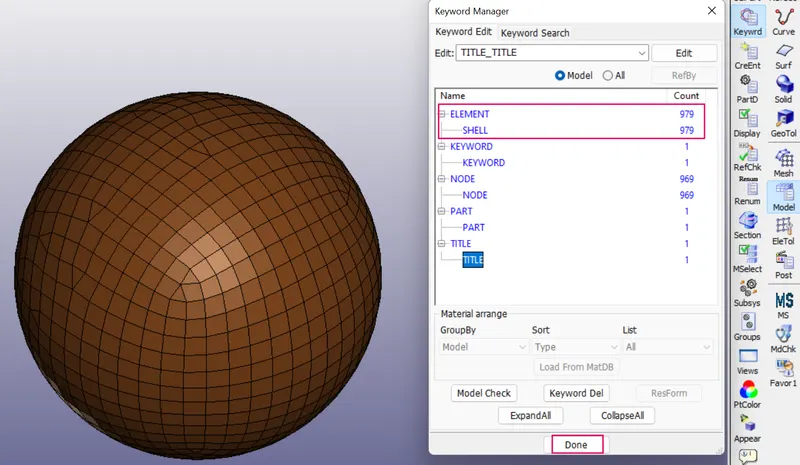
- Imported the shell elements of simple head meshed model in Ls-prepost.
- In order to check the keywords contained in the file we have to follow the below steps.
- Side bar > model and part > keyword manager > checked the model.
- Only shell elements presented in the model.Accordingh to analysis shell elements only needed.
STEP 1B : Creation of section card for the simple head model
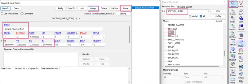
- In this whole project following by Kg-mm-ms unit sysem.
- Created the section shell for simple head model.
- Side bar > model and part > keyword manager >all > section >specified the thickness value is 2.5mm and Elform is 2 > created the new SECIDs for SH model.
STEP 1C : Creation of material card for the simple head model
- To assign the material card for sheetmetal by the following steps.
- Side bar > model and part > keyword manager > MAT > all > selected the required material for the simple head model.
- For simple head model has assigned the material is 001_ELASTIC.
- Created new ID is 1 and give title is simple_head_material and specified the values as Kg-mm-ms unit system.
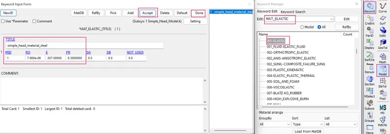
where,
Elastic material is choosen as steel
Density = 7.8 * 10⁻⁶ kg / mm³
Youngs modulus = 207 kg / mm ms²
Poissons ratio = 0.3
STEP 1D : Assign the material card and section card to the simple head model part.
- Already created the material card and section card for simple head model part , now we have to assigned the both cards to the simple head model part.
- Side bar > model and part > keyword manager >model > part > assigned the MID and SECID cards to their respective parts.
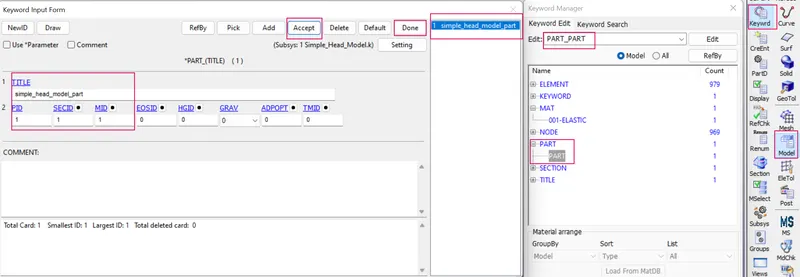
STEP 1E: DEFINE A RIGID WALL.
- The RIGIDWALL provides a easy way to define a contact between a rigid surface and nodal points of a deformable body, called slave nodes.
- A rigid wall is defined by a surface type and a group of slave nodes. Each wall can be fixed or moving. A rigid wall is a kinematic condition.So a rigid wall is created ahead of simple head model. So that simple head model should crash into a rigid wall created. And rigid wall should create at some distance from simple head model, because head model have to move with some initialvelocity. Also, we have to take care about rigid wall normal vector direction. It should be facing head model.
- In order to create rigid wall by the following steps.
- Sidebar > model and part > create entity > rigidwall > create > cheked 1n+NL option > selected the one node > check Global and XL > rigidwall created.Then we have to move the rigidwall from simple head model by the distance of 30 mm by the following steps.
- At the same time > uncheked 1n+NL option >checked translate option > specified the distance is 30 mm > rigidwall created 30 mm distance from the head model.and also make sure vector normals of the head model and rigidwall opposite to each other.so thats only the head model rebounces after strike. if vector normals of the head model and rigidwall is parallel to each other due to the head model penetrated through the rigid wall thats not needed for the analysis.
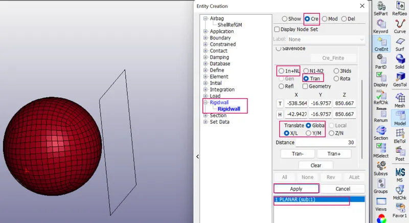
STEP 1F: ASSIGN THE INITIAL VELOCITY TO THE SIMPLE HEAD MODEL.
- To provide initial velocity to the crashbox by the following steps.
- Sidebar > model > create entity > initial > velocity > pick by part > provide initial velocity in x direction as 11.11 mm/ms >done.
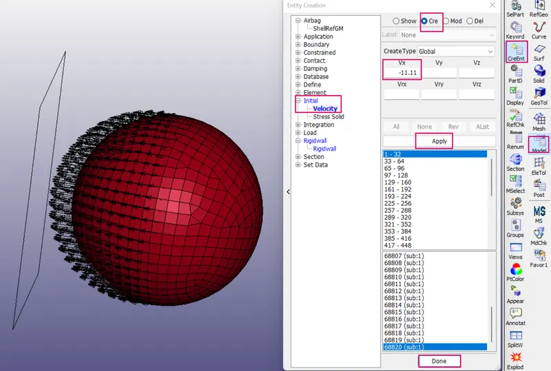
STEP 1G : Define a contact interface
- The keyword *CONTACT provides a way of treating interaction between disjoint parts.
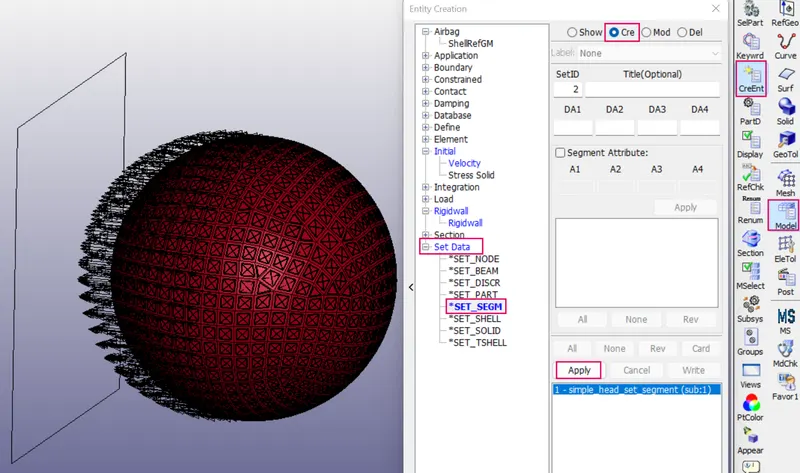
- Now we have to define contact interface. Before defining contact card, first we have to create set data segment, in which we will create segment for head model (in which we will select those elements which are going to interact during simulation).
- Define a set of segments with optional identical or unique attributes. For three-dimensional geometries, a segment can be triangular or quadrilateral. For two dimensional geometries, a segment is a line defined by two nodes and the GENERAL option does not apply.
- In order to create set of segments we have to following the below steps.
- Side bar > model and part > create entity > set data > *SET_SEG > selected the elements by part > apply and done.
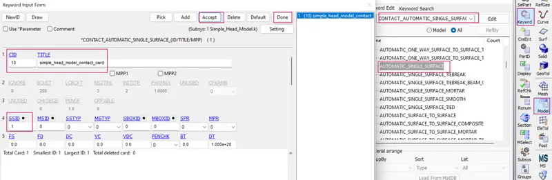
- In order to create contact card, we have to select contact automatic single surface for head model. In which slave is head model.
- In order to create contact card for the following steps.
- Sidebar > model and part > keyword manager > contact > AUTOMATIC_SINGLE _SURFACE > assigned slave set segment id > aceept and done.
STEP 1H : Define a control termination card.
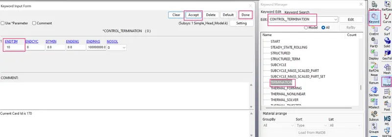
1. The main purpose of control termination card is to stop the job.
2. In order to assign the control termination card by the following steps.
3. Side bar > model and part > keyword manager > control > termination > specify termination time is 0.5ms > aceept and done.
STEP1I: Define the outputdatabases.
(1) To define the output database as Binary D3 plot.
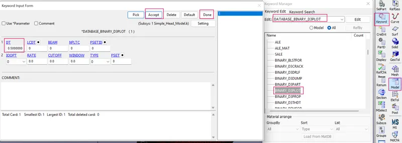
1. DATABASE_BINARY_D3PLOT ensures d3 plot files which its stores stress strain contour of the entire deformed model.
2. In order to create the DATABASE_BINARY_D3PLOT by the fllowing steps.
3. Side bar > model and part > keyword manager > database > select DATABASE_BINARY_D3PLOT > DT value is 0.5 ms is a time interval between output states > accept & done.
(2) To define the output database as ASCII.
1. ASCII can generate different outputs such as force generated in a contact like total energy and material energy etc.
2. In order to create the ASCII by the fllowing steps.
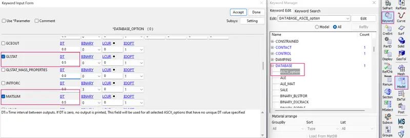
3. Side bar > model and part > keyword manager > database > select ASCII_option > check GLSTAT ,MATSUM,NODOUT and RWFORCE >specify all DT value is 0.5 > accept & done.
(3) To define the output database as extend Binary.
- Now we have everything for the simulation but to extract the results we need to create a database cards for the model.
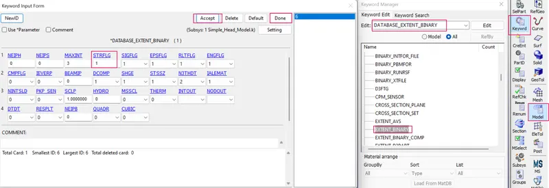
- We also need to generate the strain outputs. To do that, we can create a keyword by going to Keyword manager and selecting DATABASE > EXTENT_BINARY.
- To create the database extend binary card by the following steps,
Side bar > model > keyword manager > all > DATABASE > EXTEND_BINARY> and give STRFLG as ‘1’, this is due to extract the true strain values for the model and accept the card .
(4) To define the output database as history node.
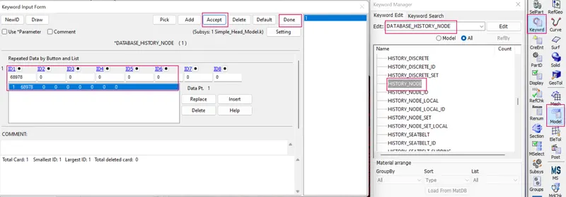
- DATABASE_HISTORY_NODE card is used to compute the HIC value of the node 68978 in the model.
- In order to create database history node by the following steps.
- Side bar > model > keyword manager > all > DATABASE > HISTORY_NODE > picked the node > accept and done.
STEP1I: Model checkup
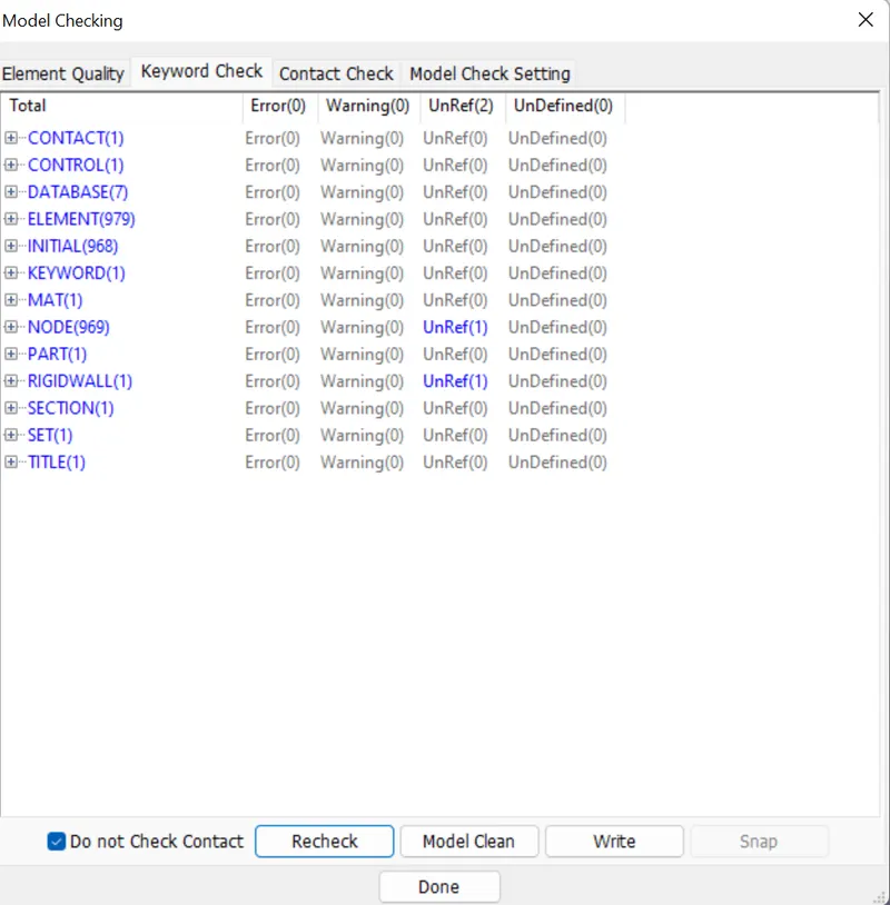
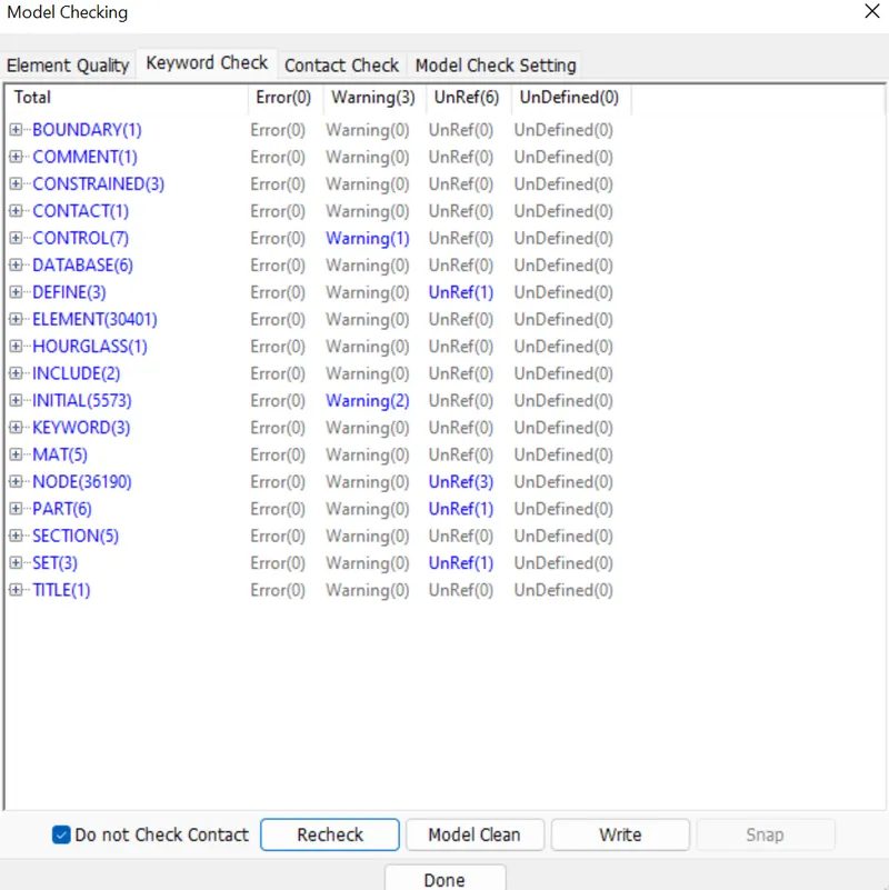
- The model is checked for any errors before solving using model checker.
- After all the errors are cleared, the drop test setup is saved and is ready to run in LS DYNA manager for solving the scenario.
- Warnings we can ignore ,once model check is run , it will look like as shown in picture below.
STEP 1K : Run the simulation.
1.. To run the using LS-run by the following steps.
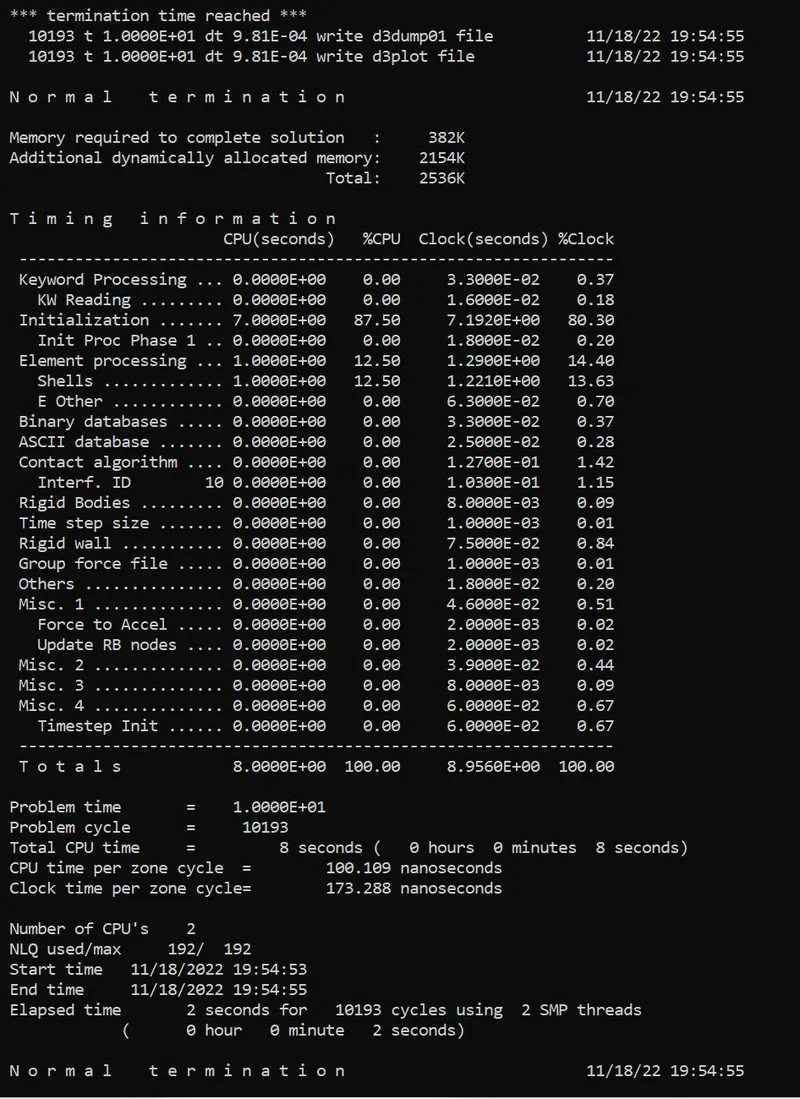
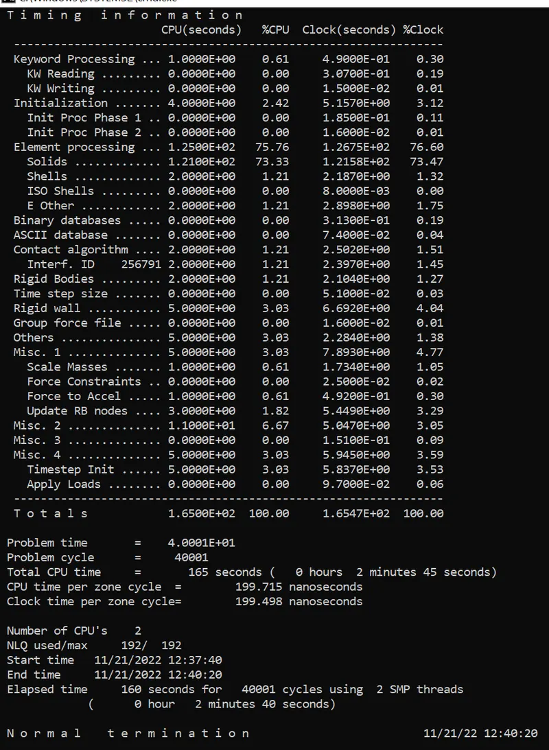
2. Title bar > file > run LS-dyna > runned the Simple_Head_Model_vs_rigid_wall > achieved normal temination. it means the model is ready for post processing.
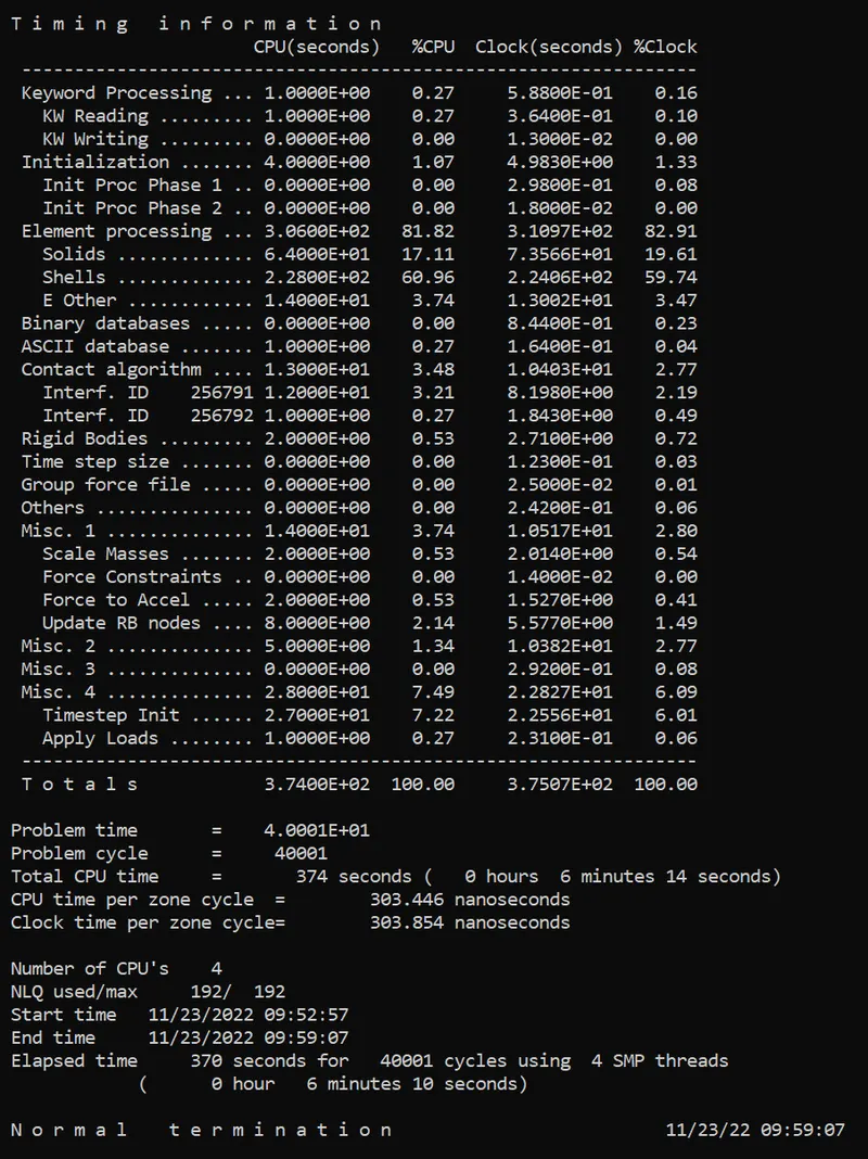
3. During simulation run window will popup as shown in picture below,
STEP 1L : POST PROCESSING
1. In order to see simulation results , we have to open output file in LS-Prepost by the following steps.
2. In LS-prepost -Title bar > file > open > LS -Dyna binary plot > selected the d3 plot file > visibled to see animation file.
3. For plot the stress contour , go to sidebar > post >fringe component > selected in which results need for analysing the problem.
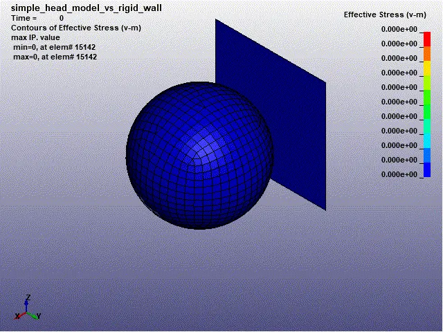
(a) Contour plot of vonmisses stress of simple head model Vs rigid wall.
Max effective stress = 0.726 kg/mm.ms²
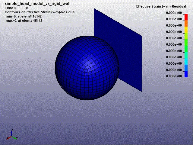
(b) Contour plot of vonmisses strain of simple head model Vs rigid wall.
Max effective strain = 2.09 *e-8
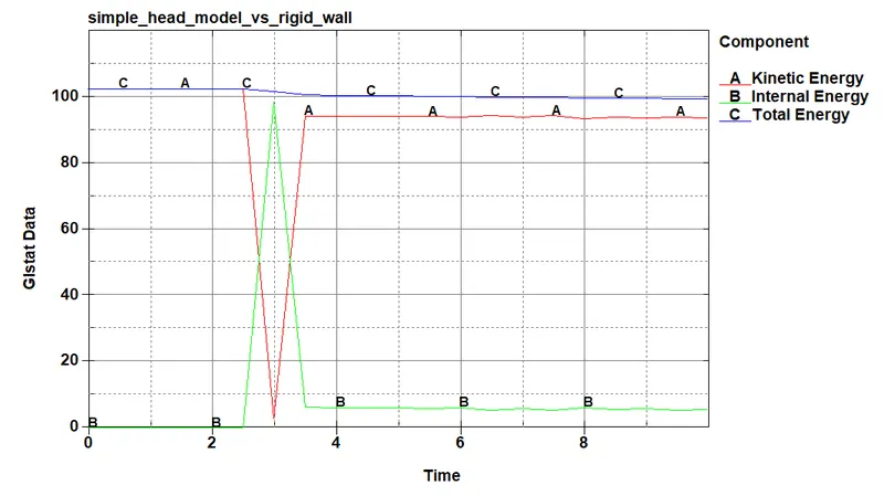
(c) Plot of energies of the simple head model vs rigidwall.
1. Max kinetic energy = 1.02 * e+02 Kg mm / ms²
2. Max internal energy = 9.85 * e+01 Kg mm / ms²
3. Total energy = 1.02 * e+02 Kg mm / ms²
(d) Acceleration plot of the simple head model vs rigid wall
(1) Max acceleration = 9.8 *e+03 mm / ms²
Avg acceleration = 3500 mm/ms²
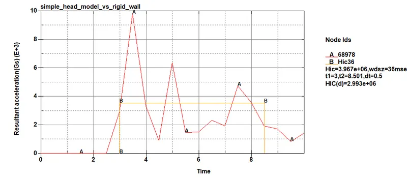
(2) Head injury criteria (HIC)
Manual calculation of HIC value
From the above graph, avarage acceleration value= 3500 mm/ms²
t1=3ms, t2=8.5 ms
={ (1/8.5-3)*(3500)*5.5}^2.5 *{(8.5-3)/1000}
= (3500^2.5) * (5.5/1000)
HIC =3.988*e6 which is nearer to the simulation plot result.
Injury criteria formula for the free motion head-form is given in equation
HIC = 0.75446 (free motion head-form HIC36) + 166.4
= 0.75446 (3.988*e6 ) + 166.4
HIC(d) = 3*e6 which is also nearer to the simulation plot result.
CASE 2 : PEDESTRIAN HEADFORM CHILD STRIKE AGAINST RIGID WALL.
STEP 2A: Define Transformation.
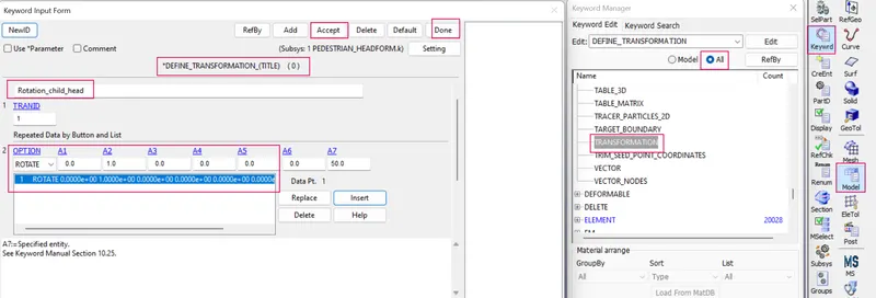
- To simulate a somewhat realistic representation of a child's head impacting a car hood, the provided child headform model has to be rotated about 500 along Y-axis.
- This is done by using *DEFINE_TRASFORMATION , here A1,A2,A3,A4,A5,A6 & A7 are direction cosines.
- Inorder to define transformation by the following steps.
- Side bar > model > keyword manager > all > DEFINE > TANSFORMATION > select option in ROTATE > rotation about Y-axis , so A2=1 , A7=500 > insert > apply and done.
STEP 2B: Define include transformation.
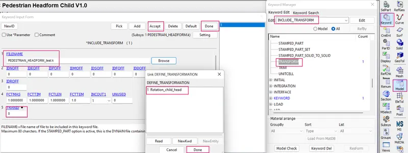
- INCLUDE_TRANSFORM uses a transformation ID defined by a *DEFINE_TRANSFORMATION command to import a model and perform the associated transformations. It also allows the user upon importing the model to apply offsets to the various entity IDs and perform unit conversion of the imported model.
- Here the *INCLUDE_TRANSFORM card is necessary for the file to be transformed and step up for the analysis. In this card, the original geometry is called through filename and defined transformation is carried out on that geometry. Transformation ID (TRANID) is set to 1 for this card. The original input file is not changed but only called for transformation.
- Then, the INCLUDE_TRANSFORM card is used to summon the rotated headform model file to the main file. The main file is saved with ‘.DYNA’ extension.
STEP 2C: Imported the DYNA forma file
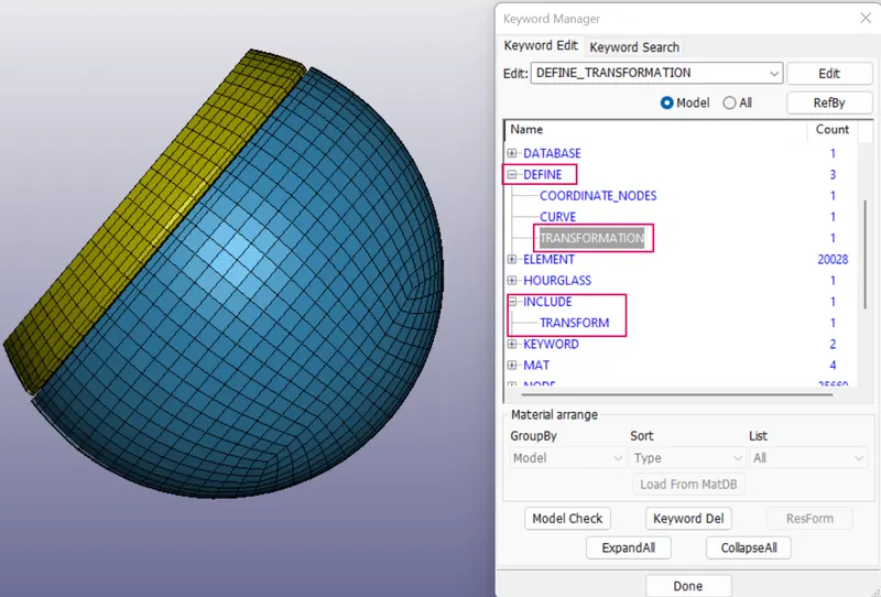
- Imported the dyna format file in ls-prepost.
- This Dyna file contains *DEFINE_TRANSFORMATION and INCLUDE_TRANSFORM cards.
- we dont make any changes in k format given file.
STEP 2D: Creation of rigid wall.
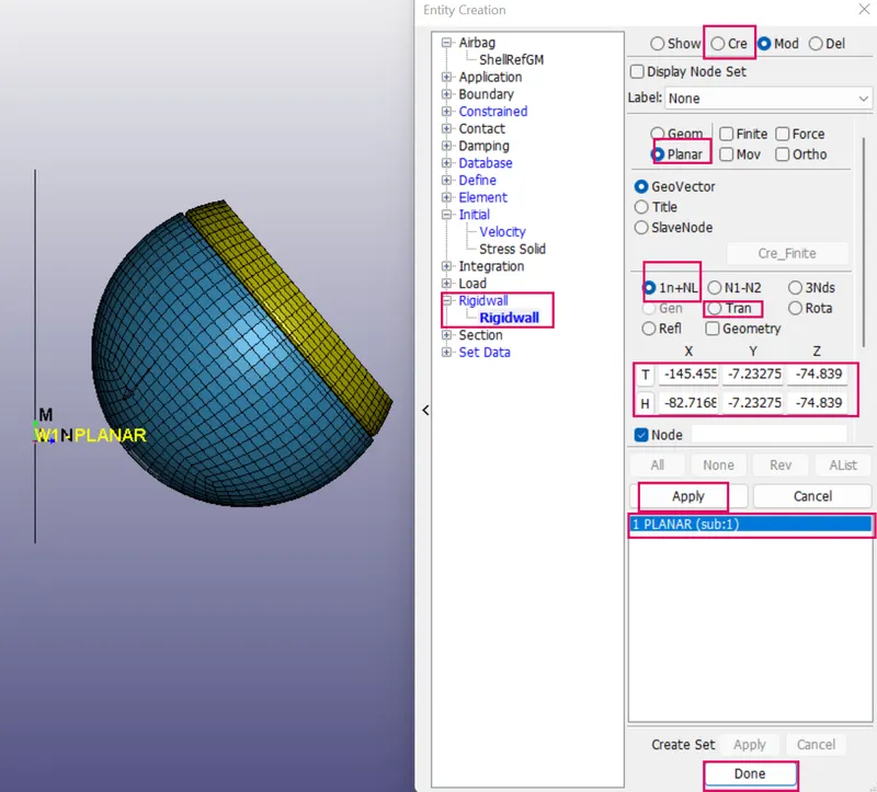
STEP 2E: Define initial velocity.
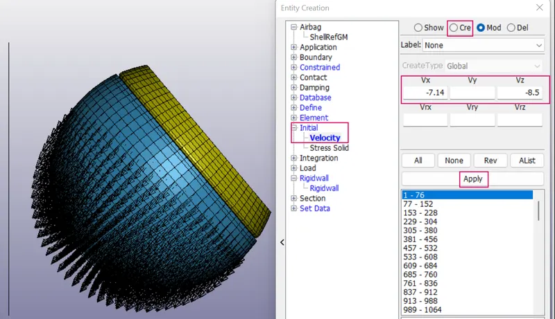
- To provide initial velocity to the child head by the following steps.
- Sidebar > model > create entity > initial > velocity > pick by part > provide initial velocity in x direction as -7.14 mm/ms and z direction as -8.5 mm/ms >done.
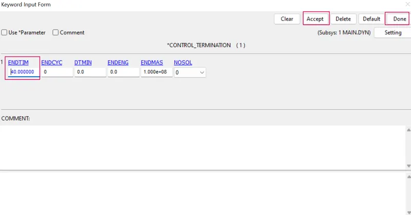
STEP 2F : Define a control termination card.
STEP2G: Define the outputdatabases.
(1) To define the output database as Binary D3 plot.
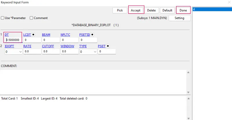
(2) To define the output database as ASCII.
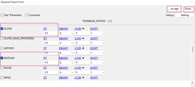
(3) To define the output database as extend Binary.
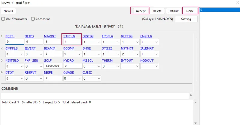
STEP2H : Model checkup
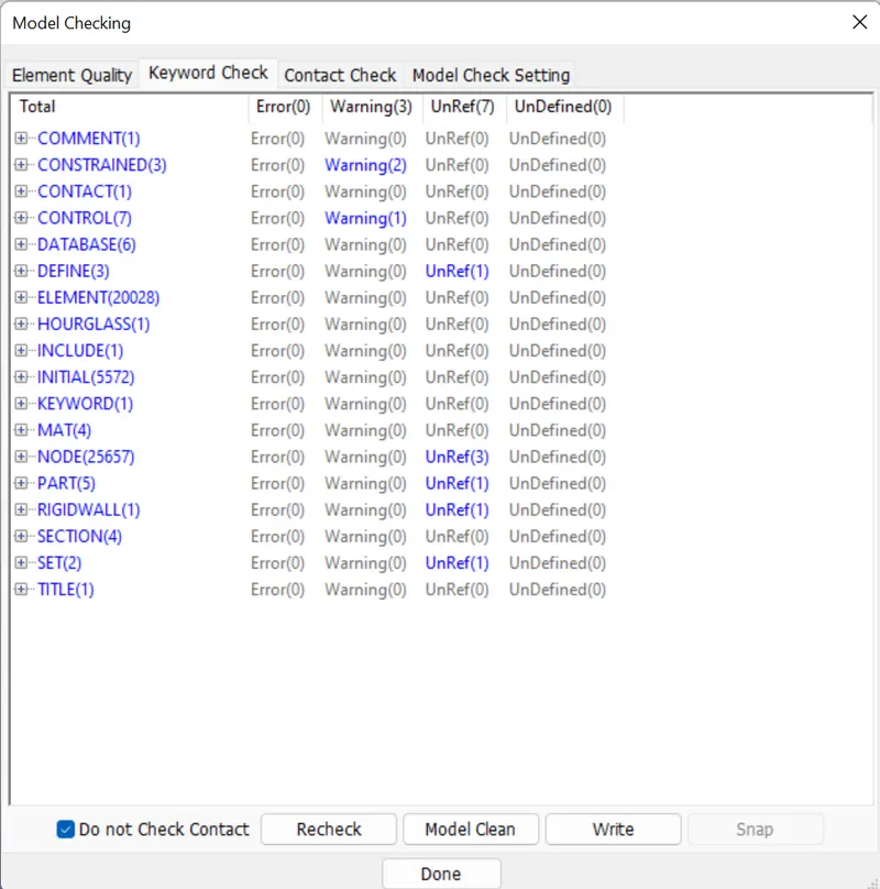
STEP2I : Run the simulation
STEP 1L : POST PROCESSING
1. In order to see simulation results , we have to open output file in LS-Prepost by the following steps.
2. In LS-prepost -Title bar > file > open > LS -Dyna binary plot > selected the d3 plot file > visibled to see animation file.
3. For plot the stress contour , go to sidebar > post >fringe component > selected in which results need for analysing the problem.
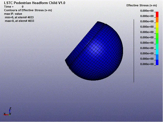
(a) Contour plot of vonmisses stress of child headform Vs rigid wall.
Max effective stress = 0.003723 kg/mm.ms²
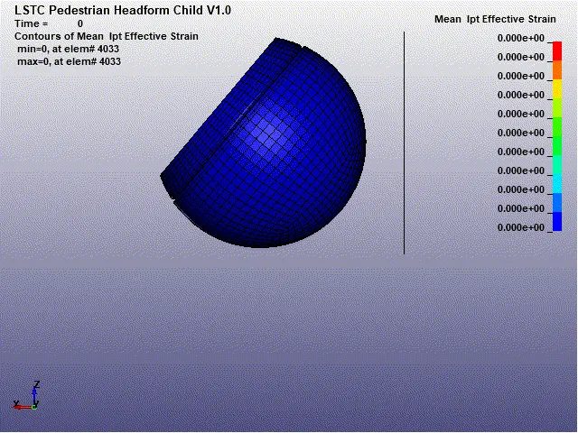
(b) Contour plot of mean Ipt effective strain of child headform Vs rigid wall.
Max effective strain = 0.0932
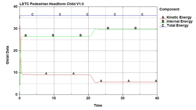
(c) Plot of energies of the child headform vs rigidwall.
1. Max kinetic energy = 36.04 Kg mm / ms²
2. Max internal energy = 30 Kg mm / ms²
3. Total energy = 36.08 Kg mm / ms²
(d) Acceleration plot of the Child headform vs rigid wall
(1) Max acceleration = 9.8 *e+03 mm / ms²
Avg acceleration = 650 mm/ms²
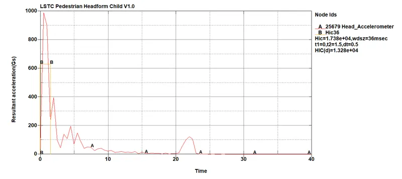
(2) Head injury criteria (HIC)
Manual calculation of HIC value
From the above graph, avarage acceleration value= 650mm/ms²
t1=3ms, t2=8.5 ms
={ (1/1.5-0)*(650)}^2.5 *{(1.5-0)/1000}
= (650^2.5) * (1.5/1000)
HIC =1.6*e4which is nearer to the simulation plot result.
Injury criteria formula for the free motion head-form is given in equation
HIC = 0.75446 (free motion head-form HIC36) + 166.4
= 0.75446 (1.6*e4 ) + 166.4
HIC(d) = 1.2*e6 which is also nearer to the simulation plot result.
Case 3: Child headform dummy model strike against hood:
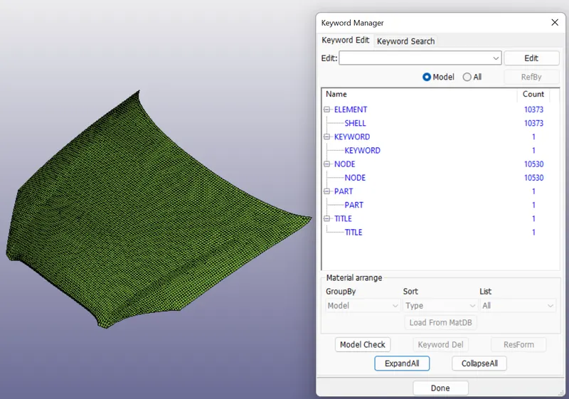
STEP 1 : Importing the mesh hood model and check the keywords.
STEP 2 : Creation of section card.
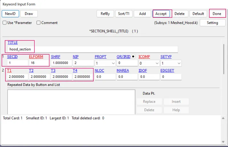
- Inorder to created the section shell for hood.
- Side bar > model and part > keyword manager >all > section >specified the thickness value is 2 mm and Elform is 16- for fully integrated shell element very fast > created the new SECIDs for hood mesh model.
STEP 3: Creation of material card.
- To craete the material card for hood by the following steps.
- Side bar > model and part > keyword manager > MAT > all > choose MAT_024_PIECEWISE_LINEAR_PLASTICITY > specified aluminium properties of hood material > accept and done.
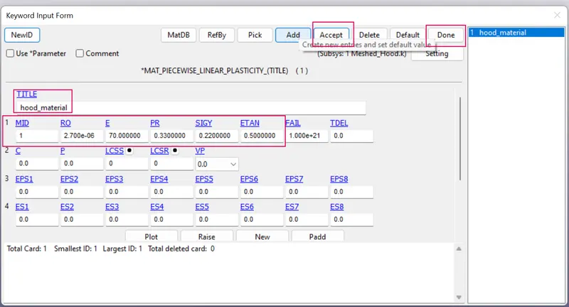
Where,
Aluminium properties
Mass density = 2.7e-6 Kg /mm³
Youngs modulus = 70 kg / mm ms²
Poissons ratio = 0.33
Yield stress = 0.22 kg / mm ms²
Tangent modulus = 0.5 kg / mm ms².
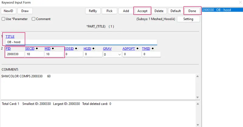
STEP 4: Assign the material card and section card to the hood part.
STEP 4: Include the rotated child head file pull into the hood file.
- This is done by using INCLUDE option in keyword manager.
- Side bar > model and part > keyword manager > INCLUDE > browsed to select the Rotated child head file > accept and done.
- Saved the meshed_hood.k file.
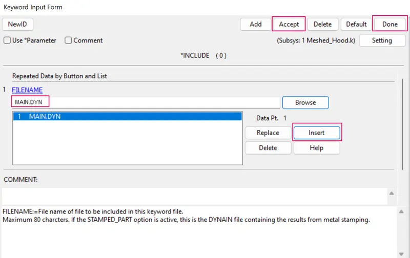
STEP 5 : IMPORT THE HOOD WITH INCLUDED ROTATED CHILDHEAD MODEL.
- Closed the previous working meshed_hood.k file.
- Imported the meshed_hood. k file in Ls-prepost and save as the meshed_hood.k file.
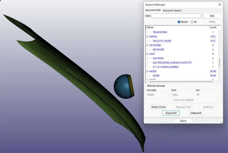
STEP 5 : Creation of automatic surface to surface contact.
- Created contact card for hood and child headform model by using the following steps.
- Sidebar > keyword manger > all > contact > AUTOMATIC_SURFACE_TO_SURFACE > assigned slave id is 2 (For child head skin ) and Master id is 6 ( for hood ) > accept and done.
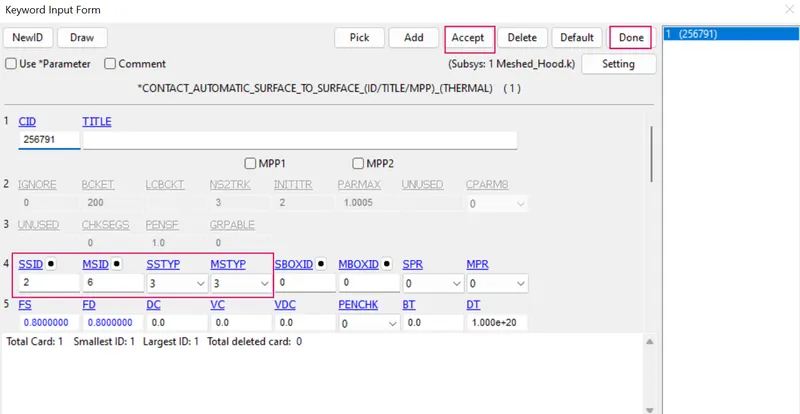
STEP 6 : Creation of boundary condition for hood.
- The Boundary SPC is defined for the Hood to constraint all the degree of freedom in translational for the set of nodes (NSID) on the edges of the hood.
- In order to create the boundary condition by the following steps.
- Sidebar > model > create entity > bounadrt > spc > create > selected the boundary nodes by path > restricted all rotation movements in all directions and accept the card.
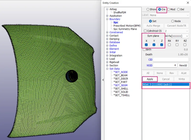
STEP 7 : Model checkup
STEP 8 : Run the simulation
STEP 9 : POST PROCESSING
1. In order to see simulation results , we have to open output file in LS-Prepost by the following steps.
2. In LS-prepost -Title bar > file > open > LS -Dyna binary plot > selected the d3 plot file > visibled to see animation file.
3. For plot the stress contour , go to sidebar > post >fringe component > selected in which results need for analysing the problem.
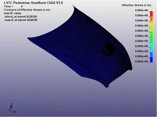
(a) Contour plot of vonmisses stress of child headform Vs hood.
Max effective stress = 0.0137 kg/mm.ms²
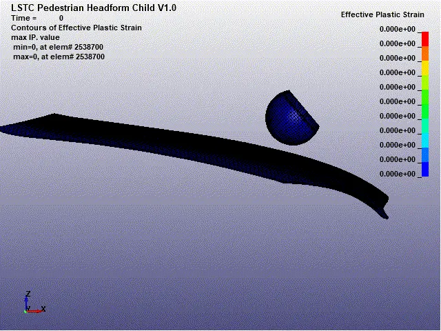
(b) Contour plot of effective plastic strain of child headform Vs hood.
Max effective strain = 0.0001735
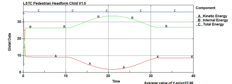
c) Plot of energies of the child headform vs hood.
1. Max kinetic energy = 36 Kg mm / ms²
2. Max internal energy = 33 Kg mm / ms²
3. Total energy = 36 Kg mm / ms²
(d) Acceleration plot of the Child headform vs hood
(1) Max acceleration = 9.8 *e+03 mm / ms²
Avg acceleration = 630 mm/ms²
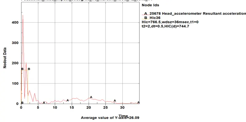
(2) Head injury criteria (HIC)
Manual calculation of HIC value
From the above graph, avarage acceleration value= 630 mm/ms²
t1=0 ms, t2=2 ms
={ (1/2-0)*(166.73)}^2.5 *{(2-0)/1000}
HIC =769.34which is nearer to the simulation plot result.
Injury criteria formula for the free motion head-form is given in equation
HIC = 0.75446 (free motion head-form HIC36) + 166.4
= 0.75446 (769.3 ) + 166.4
HIC(d) = 746 which is also nearer to the simulation plot result.
RESULT :
COMPARISON OF 3 CASES OUTPUT DATAS
| S.NO | OUTPUT DATA | SIMPLE HEAD MODEL VS RIGIDWALL | CHILD HEADFORM MODEL VS RIGIDWALL | CHILD HEADFORM MODEL VS HOOD |
| 1. | Max effective stress | 0.726 kg/mm.ms² | 0.003723 kg/mm.ms² | 0.0137 kg/mm.ms² |
| 2. | Max effective Strain | 2.09 *e-8 | 0.0932 | 0.0001735 |
| 3. | Avg acceleration | At node-68789 is=3500 mm/ms² | At node-25679 is =650mm/ms² | At node-25679 is =630mm/ms² |
| 4. | HIC | 3.97*e6 | 1.7 *e4 | 769.3 |
| 5. | HIC (d) | 2.95*e6 | 1.32 *e4 | 746 |
| 6. | Max kinetic energy | 1.02 * e+02 Kg mm / ms² | 36.04 Kg mm / ms² | 36.23 Kg mm / ms² |
| 7. | Max internal energy | 9.85 * e+01 Kg mm / ms² | 30 Kg mm / ms² | 30 Kg mm / ms² |
| 8. | Total energy | 1.02 * e+02 Kg mm / ms² | 36.08 Kg mm / ms² | 33.12 Kg mm / ms² |
CONCLUSION :
- The simple head model was defined with MAT_ELASTIC material card which implies the material is pure elastic that’s why the max effective stress is only there in the time of the impact there is no significant deformation in the simple head geometry. That’s why the HIC values are too high.
- The standard model of the child head foam with proper material was used, Since the rigid wall is undeformable so the total stress is transferred to the head and deforms the head foam geometry severely the HIC values are lower than case 1.
- The standard head model but in this case, it impacts on the car hood to study the real-life situation the hood was defined with a piecewise linear plasticity material model (Mat_024) which is a deformable model so during the impact the hood deforms significantly and reduces stress and strain on the head foam and thus reduces HIC values and the value are lower than case 2. which is what we finally required.