Assignment 2-RADIOSS Engine File Editing & 3D Meshing Challenge
RADIOSS Engine File Editing & 3D Meshing of arm bracket and housing
Aim:
- To calculate the values & editing values on the engine files and also to perform the hexa meshing of arm bracket and housing on different geometries by using hypermesh.
Objective:
- To check the material properties and speed of the sound in rail rail.
- To calculate the time for sound to travel over length of the rail.
- To edit the engine file for termination time and animation time step.
- To perform shell meshing and solid tetra meshing of housing component and to fix tet collapse issue on housing.
- To perform Hexa meshing of arm bracket .
Data base :
(1) Inputs :
- Length of the rail is 1000 mm.
- Frequency of animation output to a time that will give 20 animation steps(/ANIM/DT).
(2) Quality criteria:
- Target tet size=5mm
- hex size=10mm
- Tet collapse=0.15.
Procedural steps :
1. Check the material properties of the rail component and calculate the speed of sound in steel rail.
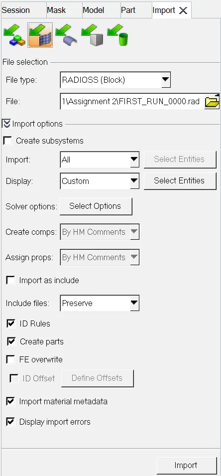
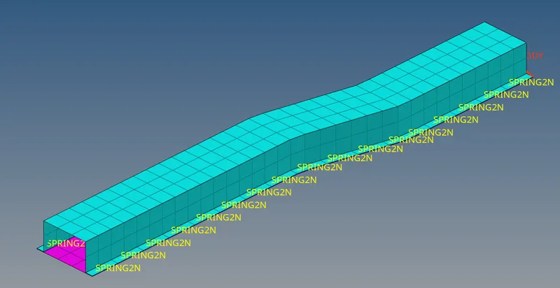
- Inorder to import the .rad file by the following steps.
- File > import > solverdeck > file type- radioss block > file name as FIRST_RUN_0000.rad > imported it.
- Inorder to check the material properties of rail component by the following steps.
- Model > material > steel > checked the properties of steel.
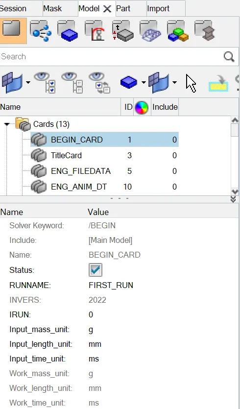
- Inorder to check the unbit system of rail component by the following steps.
- Model > cards > BEGIN_CARD > checked Gm mm ms unit system followed.
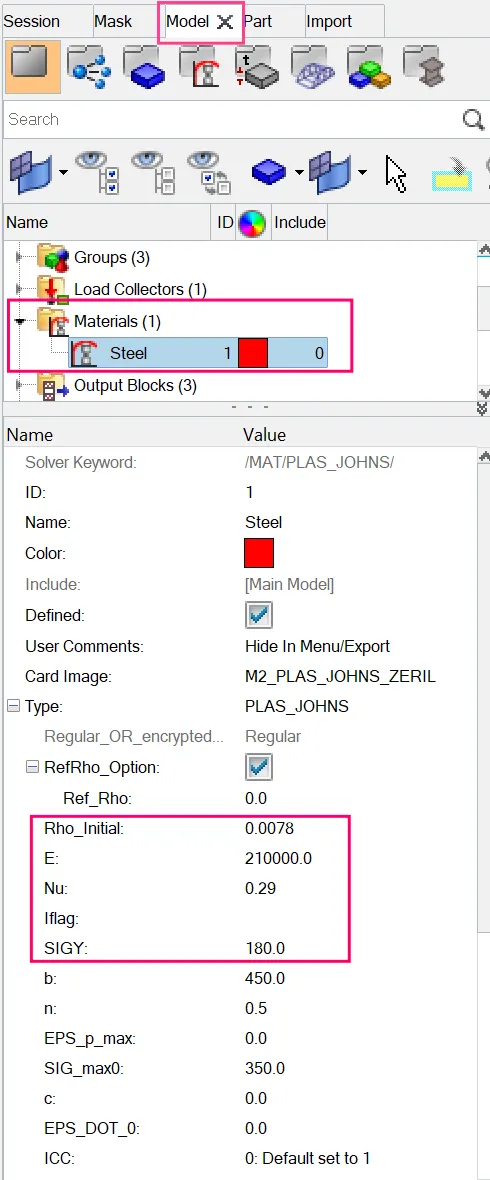
From the above picture properties of steel rail as,
Youngs modulus = 210000 N/mm2
Density = 0.0078 gm /mm3
Poissons ratio = 0.29
Speed of sound in steel rail, c = √(E⁄p)
= √ 210000 / 0.0078
c = 5188.74 mm / ms.
2. The length of the rail is about 1000 mm and to calculate the time takes for a shock wave to travel from one end of the rail to the other.
Time for sound to travel length of the rail = Length of the rail / speed of the sound.
= 1000 / 5188.74
T = 0.1927 ms.
3. Time for sound to travel length of rail
Time for sound to travel length of rail = 0.1927 ms
Time for a shock wave to travel from one end of the rail to the other end is equal to the time for sound to travel over length of rail.
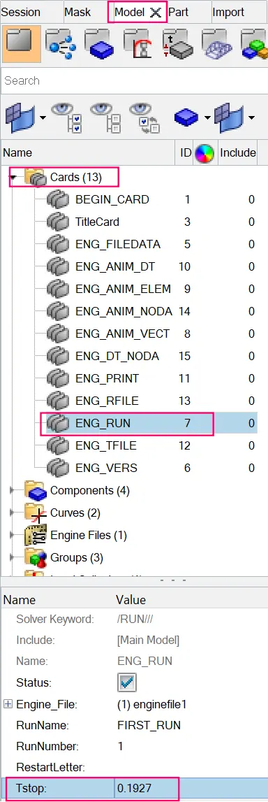
4. Termination time :
Termination time = Time for sound to travel length of rail = 0.1927ms
Inorder to update the termination time or Tstop time in model cards by the following steps.
Model > Cards > ENG_RUN > update the termination is 0.1927 ms.
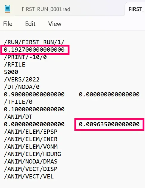
5. Set the frequency of animation output to a time that will give 20 animation steps(/ANIM/DT)
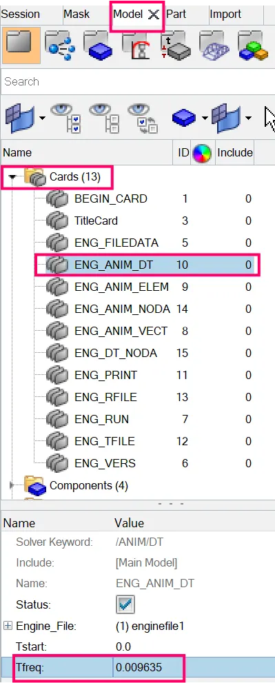
T frequency = Termination time / animation time steps
= 0.1927 / 20
= 0.009635.
In order to edit the card by the following steps.
Model > Cards > ENG_ANIM_DT > updated the frquency value.
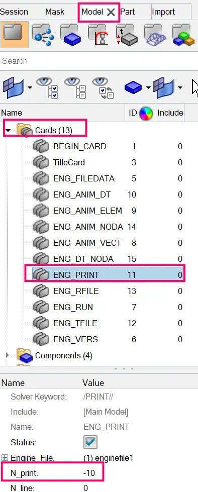
6. Change /print -10.
- Here the print value -10 has been already setted default,So no need to change the print value.
- After entering the values in the control cards.
- Run solver.
- To do that,Go to Analysis panel in Panel Area > Radioss > Select the Input File > Radioss.


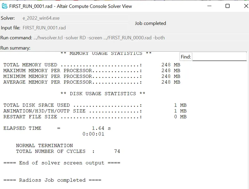
- After selecting the input file and completing the set up to run the solver.
- Radioss will pop the solver view stating Radioss Job Completed.
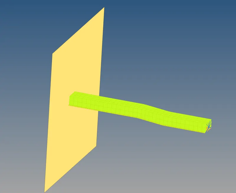
Check FIRST_RUN_00001.rad file
- After the end of the solver output,Go and check the whether the engine has been edited or not.
- To check,Go to file location where you have saved the starter file.
- Open the FIRST_RUN_00001.rad file with notepad.
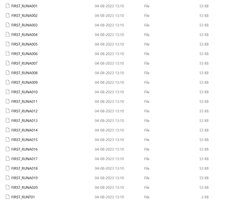
Check animation files
- We have eneterd the T frequency value to create 20 animation files,The 20 animation files have been created which is shown in below,
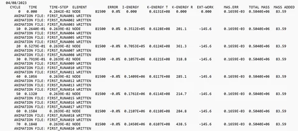
Check output FIRST_RUN_0001.out file
- Here in the output file FIRST_RUN_0001.out we can see in every specific cycle,the three animation files are created which is shown in below image as ,
3D TETRA MESHING OF HOUSING MODEL
PART 1: TETRA MESHING ON THE HOUSING MODEL BY 2D TO 3D CONVERSION METHOD.
STEP 1 : IMPORTING THE HOUSING MODEL
- Imported the stp file of housing model by import as a geometry option.
- File > import > geometry > selected the file type as STEP > browsed to selected the component > imported it.
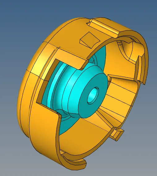
STEP 2 : DELETING THE SOLID ENTITIES OF HOUSING
- Set the model as a by topo mode .
- In housing , inner component only have solid entities but outter component have surface only, so first of all deleted solids of the inner component.
- Deleted the solid entities of inner component housing model by, delete option > selected the solids > deleted it.
Surface entities
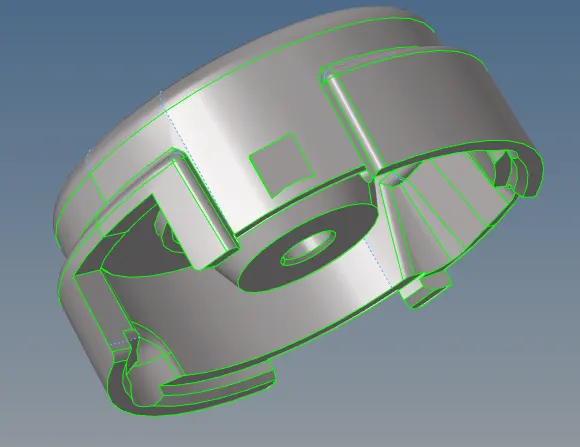
PART 1A :TETRA MESHING ON THE OUTTER COMPONENT OF HOUSING MODEL AND HUB
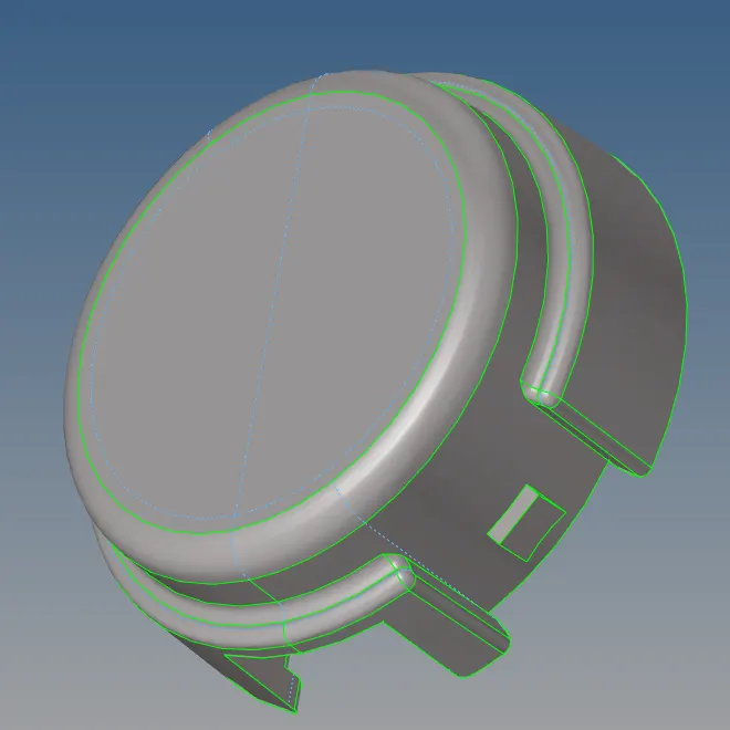
STEP1A : GEOMETRIC CLEANUP ON THE OUTTER COMPONENT OF HOUSING MODEL
- Switch on the outter component only then,to check if there's any extra surface or free edges or missing surfaces
are present or not. - For this enable wireframe geometry mode and then try to observe and find irragularities and
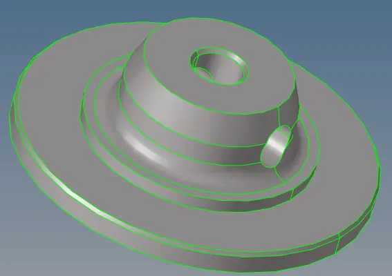
discontinuities in the model. If found then fix it manually. - Removed the lines, where the below minimum length criteria.
Geometric cleanup of housing model
Geometric cleanup of hub
STEP 1B : SET THE MESH PARAMETERS AND QUALITY CRITERA VALUES
- Before go to the meshing process, set the mesh parametes values and quality criteria values as per the
given data for model-1 housing part. - Title bar > Preferences > parameter file settings > basic > changed the parameter values as per given data.
Title bar > Preferences > quality criteria file settings >2D and 3D options > changed the parameter values as per given data.
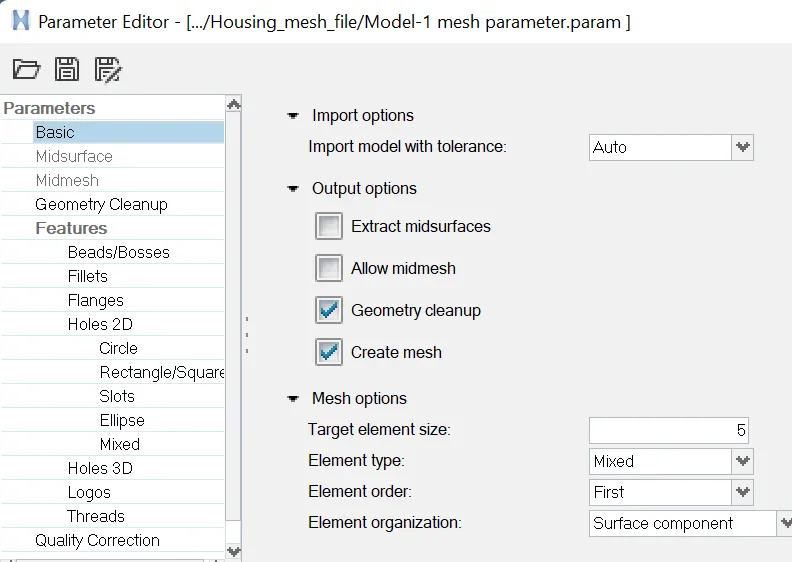
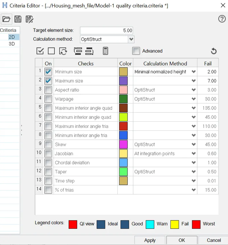
STEP 1C: SURFACE MESHING ON OUTTER COMPONENT OF THE HOUSING MODEL AND HUB MODEL
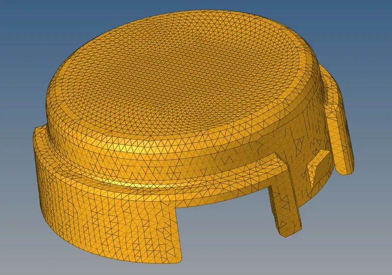
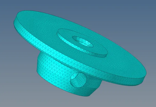
- Performed surface meshing on the outter component by automesh method.
- Mainmenu > 2D > automesh > set the target element size = 5mm > selected the surfaces > meshed it.
- Fixed the elements which are failing for quality of min length and max length errors
- Mainmenu > 2D > Quality index > smooth and element optimize options to fixed the quality errors.
- Mainmenu > 2D > element cleanup > selected the elements which are failing for quality > cleaned the failing elements.
2D meshing of outter component
2D meshing of hub
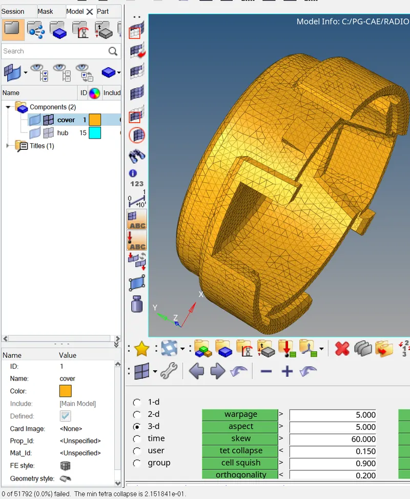
STEP 1D: CONVERSION OF SURFACE MESHING INTO SOLID MESHING OUTTER COMPONENT OF THE HOUSING MODEL AND HUB MODEL.
- Converted 2d meshing of housing into 3D meshing by the following steps.
- Main menu > 3D > Tetra mesh > selected the elements by display >check simple pyramid > meshed it.
- Then checked the quality of the mesh by Mainmenu > tool > check elements > 3D > tet collapsed elements failed are shown
- Failed the TET collapsed elements are cleared by using Tetra Remesh.
- Main menu > 3D > Tetra mesh > selected the elements by display >checked free boundary faces is fixed and mesh to current comp > remeshed it.
- Elements failed for tet collapse are 0(0.0%)
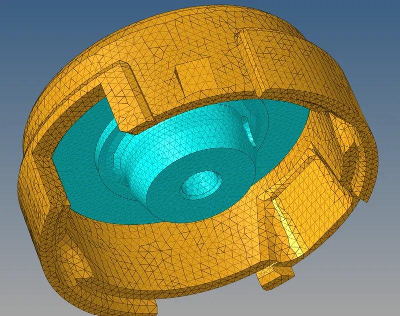
FINAL ASSEMBLY FE MODEL OF HOUSING AND HUB
HEXA MESHING OF ARM BRACKET MODEL
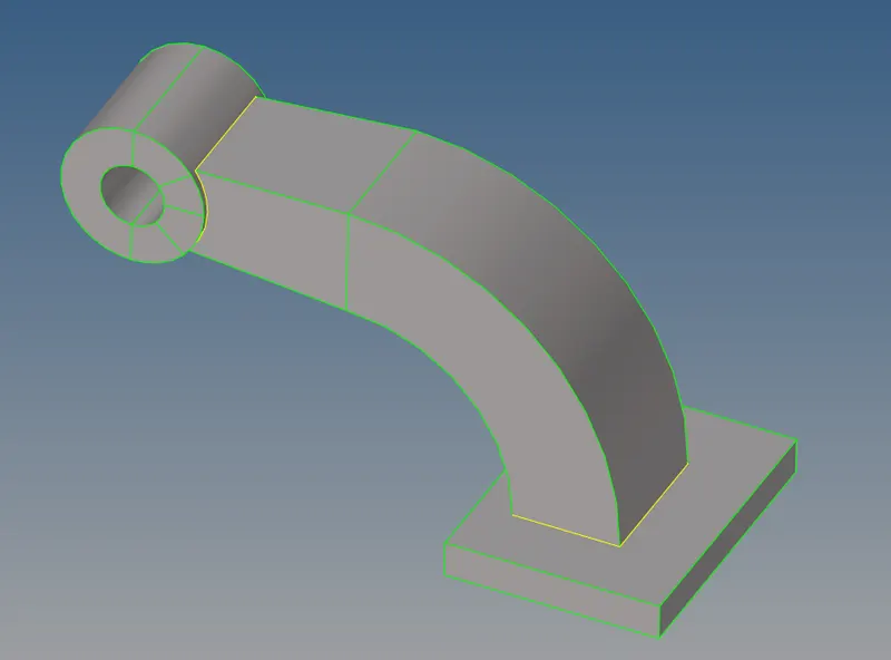
STEP 1 : IMPORTING THE ARM BRACKET MODEL
- Imported the stp file of housing model by import as a geometry option.
- File > import > geometry > selected the file type as STEP > browsed to selected the component > imported it.
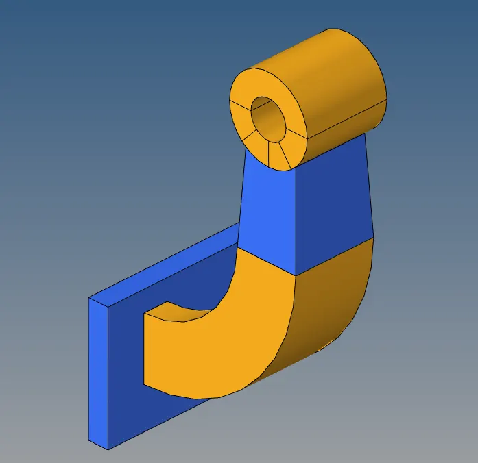
STEP2:
- Next switch to the topo mode and view the model ,and start meshing thr arm bracket component with hexahedral elements.
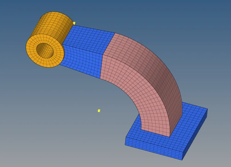
- Now there are four components in the model called Base,Arm Curve,Arm Straight and Boss.
- Isolate the Base Component only and mesh the component with the shell elements and then mesh with the hexahedral elements.
STEP3:
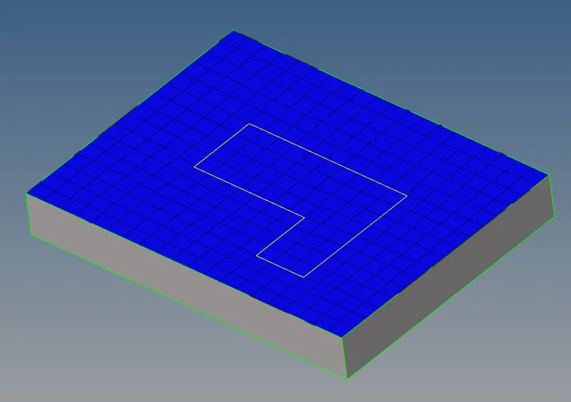
Quad Meshing of base component.
- Now first mesh the upper surface with 2D shell elements and then create hexa elements.
- Go to the Automesh Panel > Surfaces > Element Type:Quad > Enable Align,Size,Skew.
Hexa Meshing of base component.
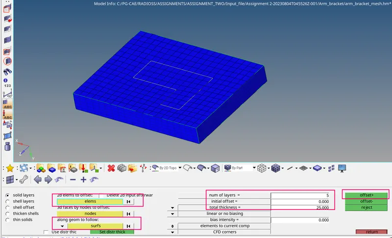
- Now Go to 3D panel > Element Offset.
- To create hexa elements.
- Now select the elements to offset.
- Select all the side surfaces of base component to follow along the geometry.
- Give the number of layers as 5, to get 5 row of elements over the base component.
- The total thickness of base component is 25.Give the value as 25 and offset the elements to create hexa elements.
Hexa Meshing of arm curve.
- Masked the hexa elements in the base component.
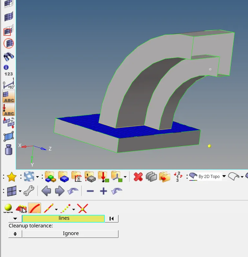
- To spin the elements,First we have to create a center node called base node to create hexa elements.
- To Create,Go to Geometry > Nodes > Arc Center > Lines > Create.
Base Node created
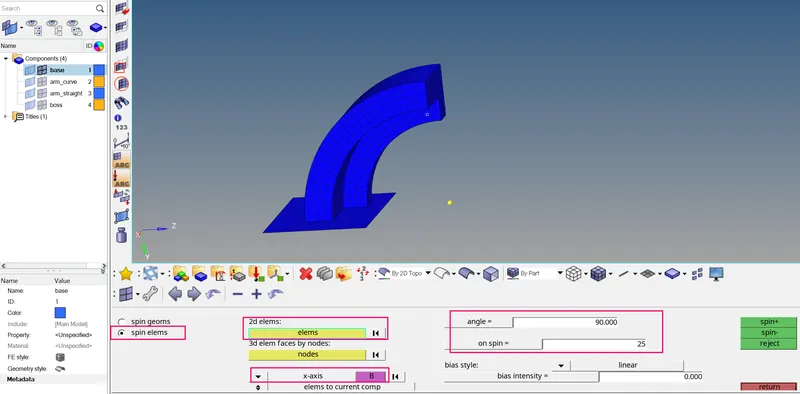
- Here select the elements to spin in 2D elements option .
- Select x axis to spin the elements in x axis and select the base node.
- Specify the angle as 90 through which to spin the elements.
- Specify 25 number of elements to generate along the path of the spin.
- And spin - in opposite direction.
Hexa Meshing of arm straight component.
- To mesh this arm straight component,The linear solid tool is used to mesh the component with the hexa elements.
- For this tool,We should have both source geometry and destination geometry.
- The source geometry 2D Quad Shell Elements has been created by using faces tool as by the following steps.
- Tool > faces > elements > selected the base hexa elements of the arm curve.
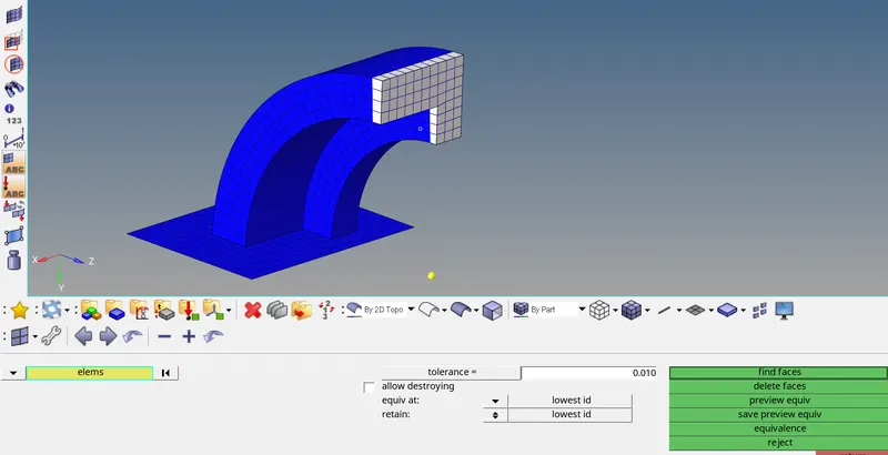
- Now mesh the destination geometry with same number 2D Quad Shell Elements.
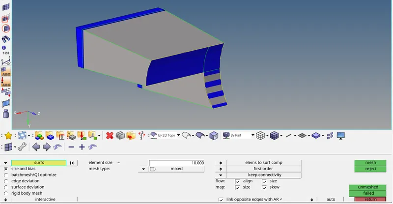
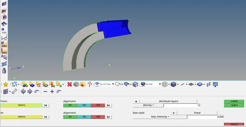
- Here select the elements in the source geometry and select the elements in the destination geometry by the following steps.
- Mainmenu > 3D > linear solid > elect the elements in the source geometry and select the elements in the destination geometry.
- Now align the nodes in the both source and destination geometry.
- Give an appropriate density value and hit on solids to create hexa elements.
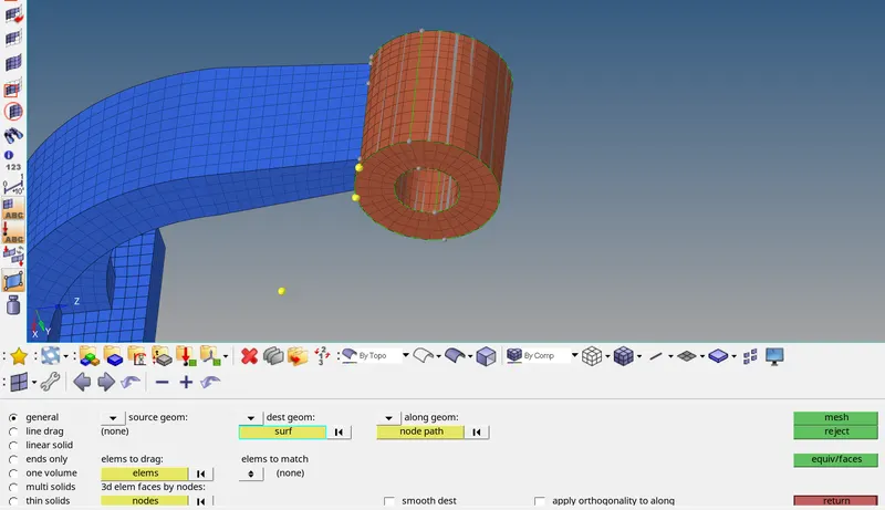
Hexa Meshing of boss component.
- Mesh the top surface of boss with 2D Quad Shell Elements.
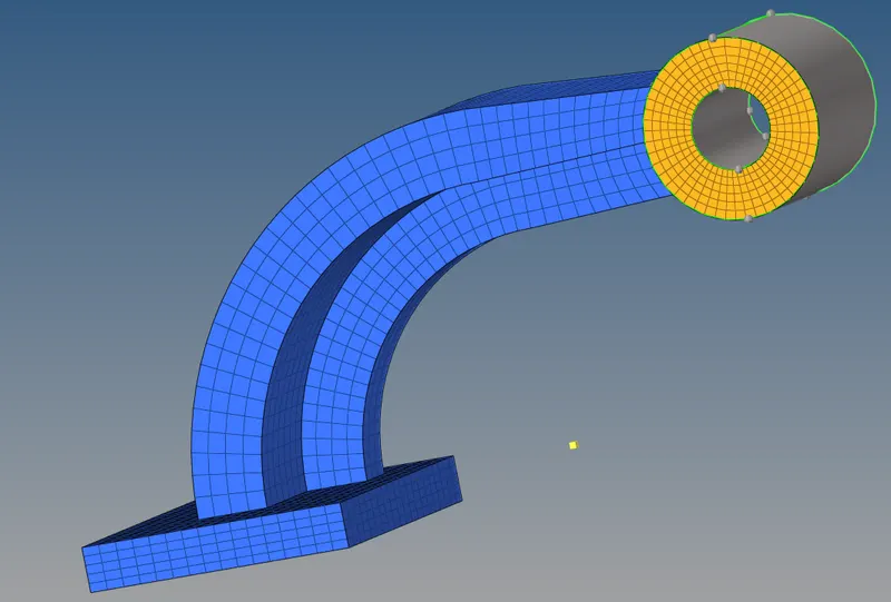
2. Now project the node to the surface to select the node path in along geometry.
To project,Go to Tool > Project > To Surface > Nodes > Duplicate > Select Surface > Surface Normal > Project.
3. Mainmenu > 3D > solidmap > general > elements to drag -selected 2d elements in boss > dest geometry > along geometry as node path > meshed it.
FINAL FE MODEL OF ARM BRAKET WITH HEXAHEDRAL ELEMENTS
Result :
- Hence the Engine File has been edited successfully with the values calculated.
- Hence the 3D Meshing has been generated for Housing Model with Tetra Elements.
- Hence the 3D Meshing has been generated for the Arm Bracket Model with Hexa Elements.
Learning Outcome:
In this Week 2 Challenge,I came to know
- The types of files for the Radioss Block
- How to edit the Engine File.
- How to mesh the component with hexa elements.