Week 6-Meshing of Hood Challenge
2D MESHING OF THE AUTOMOTIVE HOOD
AIM:
- To do geometry cleanup of the hood model.
- To generate midsurface of the hood model.
- To Generating mesh on the hood with low tria concentration and proper mesh flow.
- To ensurel hood model will pass all the given quality parameters.
GIVEN DATA :
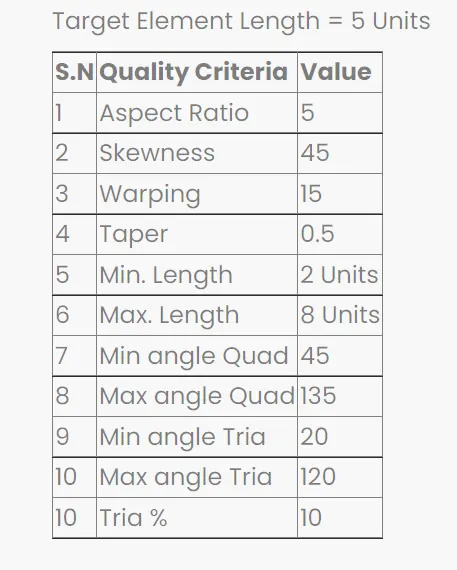
GIVEN MODEL :
- HM file of hood model.
- STP file of hood model.
SOFTWARE USED :
Preprocessing software - Hyperworks Desktop-2022.
THEORETICAL VIEW :
INTRODUCTION OF THE AUTOMOTIVE HOOD :
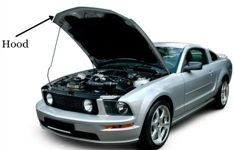
- The hood or bonnet is the hinged cover over the engine of motor vehicles. Hoods can open to allow access to the engine compartment,or trunk on rear-engine and some mid-engine vehicles for maintenance and repair.
- Car hoods are typically constructed from steel and sometimes from aluminum.
FUNCTION OF THE AUTOMOTIVE HOOD :
- Its main function is to direct access to the engine, bettry and other crucial parts of the cars for repair and maintenance and to protect these parts from direct sunlight and dust.
- It also gives good looks and,help to design car aerodynamically stable.
- Sometimes it is required to supply pure air so filter is provide on the bonnet to supply filtered inlet air.
- Hoods are provided with different vent designs for cooling purpose of an engine and carburator at high speed.
- scoops on hood having another function of supply of air for supercharger in case of supercharged engines.
- latest function of hood to handle heavy engines with supercharger outside.
PROCEDURAL STEPS :
PART 1 : INNER BODY OF THE HOOD.
STEP 1A : IMPORTING THE CAD MODEL
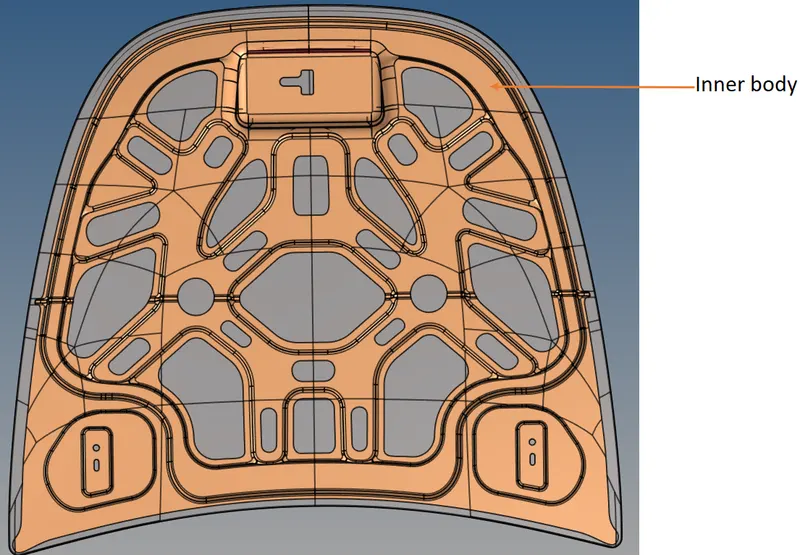
- Imported the hm file of hood inner body into the hyperwork envoronment.
- Import the .hm model file using File > import > model >Click on the file > imported it.
Imported the .hm file of hood model
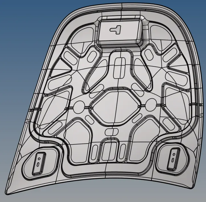
STEP 1B : DELETING THE SOLID ENTITIES.
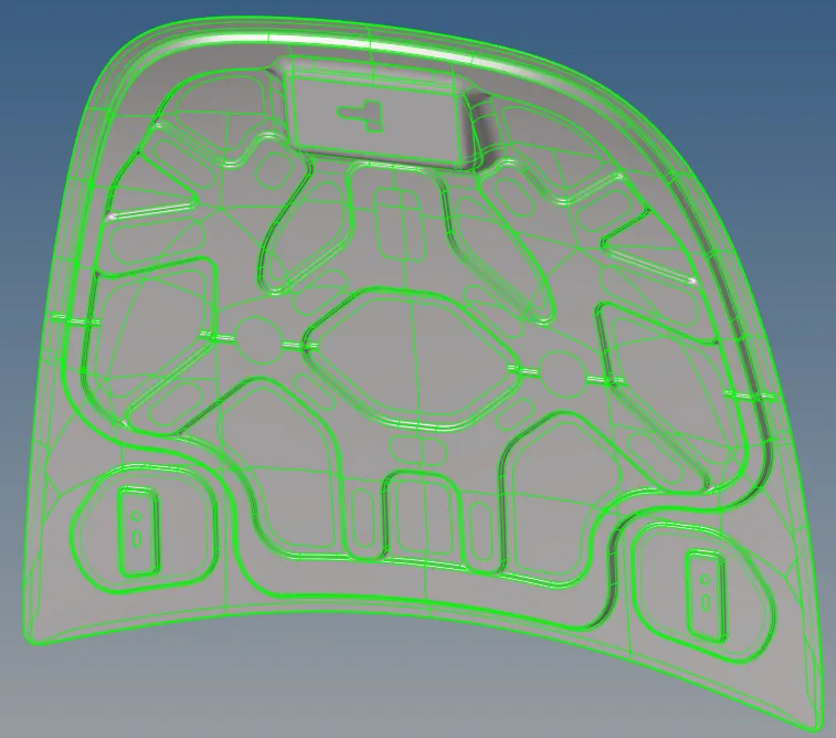
- Now changed the geometry from auto mode to topo mode.
- To delete the solid entities of all the components by Tools > delete > selected by solid option > deleted it.
Hood model with surface only
STEP 1C : GEOMETRY CLEANUP ON THE INNER BODY OF THE HOOD.
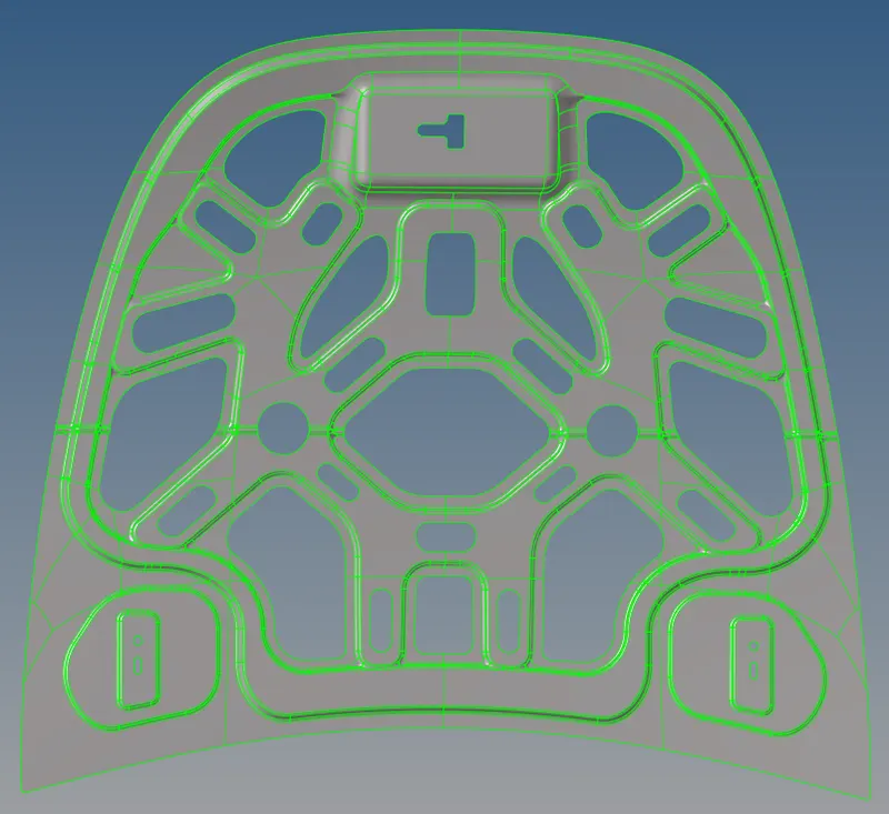
- Switch on the inner body only then,to check if there's any extra surface or free edges or missing surfaces are present or not. For this enable wireframe geometry mode and then try to observe and find irragularities and discontinuities in the model. If found then fix it manually.
Geometri cleanup of the inner hood
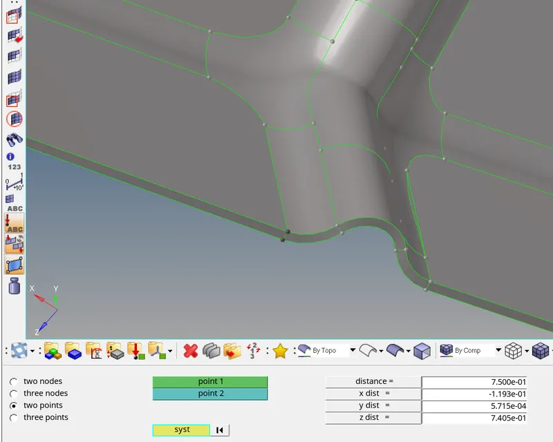
STEP 1C : THICKNESS MEASUREMENT ON THE INNER BODY OF THE HOOD.
- Measured the thickness of the inner body of the hood by Geometry > distance > 2 points > selected the 2 points > distance measured is 0.75 mm.
Measured thickness of the inner body of the hood.
STEP 1D : MIDSURFACE EXTRACTION ON THE INNER BODY OF THE HOOD.
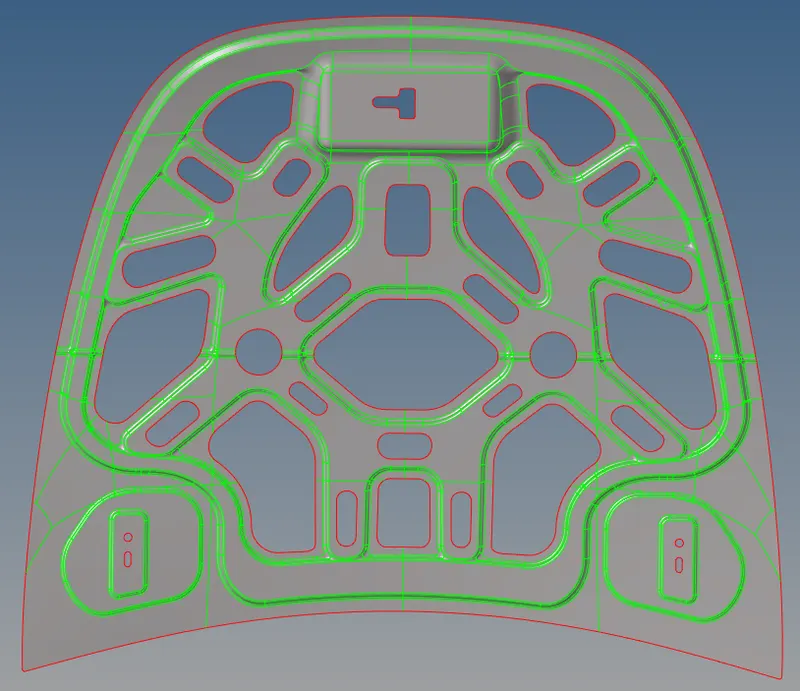
- Midsurface extracted by Geometry > midsurface > extract option - skin offset > selected the all surfaces > extracted it.
Midsurface of the inner body of the hood.
STEP 1E : MATERIAL PROPERTIES AND THICKNESS ASSIGNING.
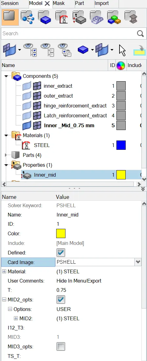
- Created common material as STEEL for all parts of the hood.
- Then Created new property for inner hood, Set card image as a SHELL ,set the material as STEEL and assigning the thickness =0.75mm.
- Created material card and assigned material to the property card and then will assigned property card to inner hood midsurface component.
STEP 1F : IDENTIFY AND DELETING THE SYMMETRY SURFACES OF THE INNER HOOD
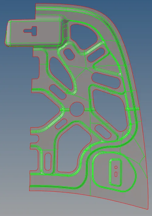
- Deleted the one side of the smmetry surfaces of the inner hood.
- Tools > delete > selected the one side of the symmetry surfaces > deleted it.
- Before go to the meshing toggled some lines in the geometry with below minimum length criteria.
- Mainmenu > geometry > toggle edge > selected the unmwanted lines > toggled it.
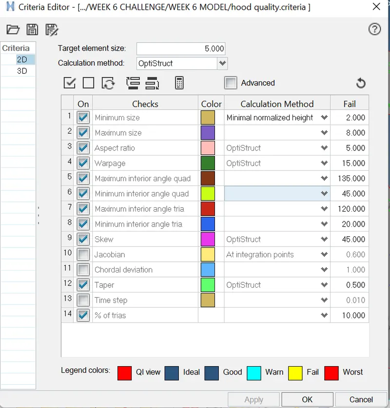
STEP 1G: SET THE MESH PARAMETERS AND QUALITY CRITERA VALUES
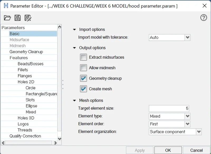
- Before go to the meshing process, set the mesh parametes values and quality criteria values as per the given data.
- Title bar > Preferences > parameter file settings > basic > changed the parameter values as per given data.
- Title bar > Preferences > quality criteria file settings > changed the parameter values as per given data.
STEP 1H: 2D MESHING OF THE INNER HOOD
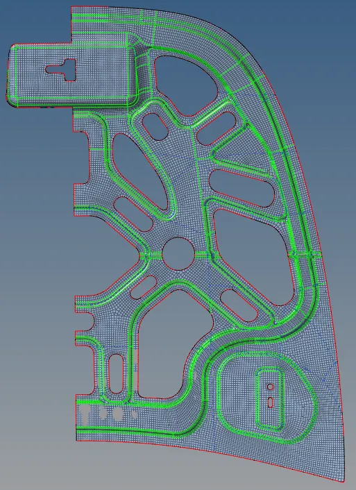
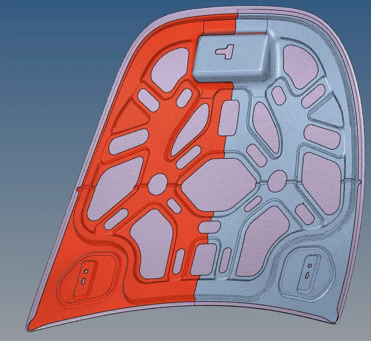
- Performed meshing on the inner hood by automesh method.
- Mainmenu > 2D > automesh > set the target element size = 5mm > selected the surfaces > meshed it.
- Achieving proper mesh flow was followed by the below steps.
(a) Reduced the trias concentration by Mainmenu > 2D > edit element > split > selected the elements > draw a spliiting line by points
> splitted the elements.
Then Mainmenu > 2D > edit element > combine > selected 2 trias > combined into quads.
(b) (or) Mainmenu > 2D > split > click refine elements > selected the elements by path > splitted into elements.
Then Mainmenu > 2D > edit element > combine > selected 2 trias > combined into quads.
(c) Mainmenu > 2D > quality index > cleanup tools > Drag tria elements and combine tria elements > reduced the no of trias .
(d) Reduced the no of trias by Mainmenu > 2D > replace > node with other node > disabled the tria element.
(e) After spliitting the elements to perform smmoth operation to get uniform mesh flow by,
Mainmenu > 2D > smooth > plates > selected the elements > set the iterationvalues as 1 or 10 > smoothed it.
(f) (or) Mainmenu > 2D > quality index > cleanup tools > smooth > selected the elements > smoothed it.
(g) After splitting the elements alignment node will be changed , so nodes will aligned by
Mainmenu > geometry > node edit > aliogn node > selected the 1st and 2nd end node and selected nodes needs to be aligned.
(h) To get the proper alignment of node with midsurface construction line by ,
Mainmenu > tools > project > click to line option > selected the nodes wants to align and selected the construction line and vector by nodes > alligned it.
(i) To improve the mesh flow by using rebuild mesh option,
Mainmenu > 2D > rebuild mesh > selected the elements > proper mesh flow got it.
2D meshing of half of the inner hood
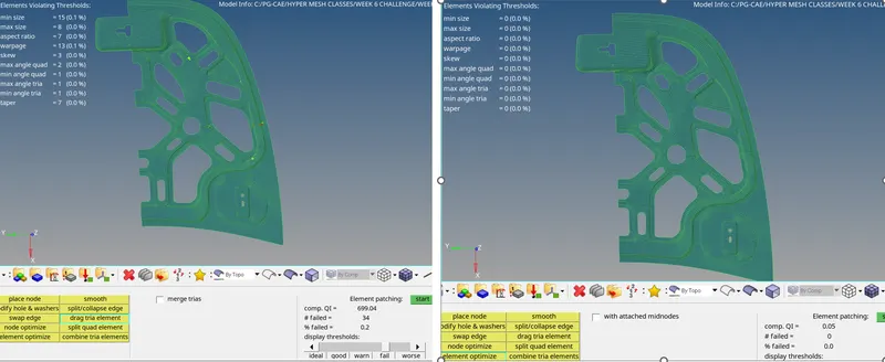
STEP 1I : CHECKING AND FIXING THE ELEMENTS FAILING FOR QUALITY CRITERIA.
- Mainmenu > 2D > quality index > cleanup tools > set display threshold as fail > idenetified the elements which are failing for quality .
- Then , go to mainmenu > tools > check elements > 2D > set the quality criteria values a sper the geven data.
- Check the warpage quality by selected the elements which are failing for the warpage by save failed option.then go to mainmenu > tool > mask > selected the elements by retrieve > mask > reverse > showed the elements failing for warpage.
- Then go to the unmask adjacent option showed the adjacent elements, then its fixed by place node ,remesh, rebuild mesh options , element optimization and smooth in quality index.
5. Then fixed the elements which are failing for aspect ratio, min length , max length , skewness , taper , min & max angle trias and min & max angle quads.
Before fixing the failing quality of half of inner hood After fixing the failing quality of half of inner hood
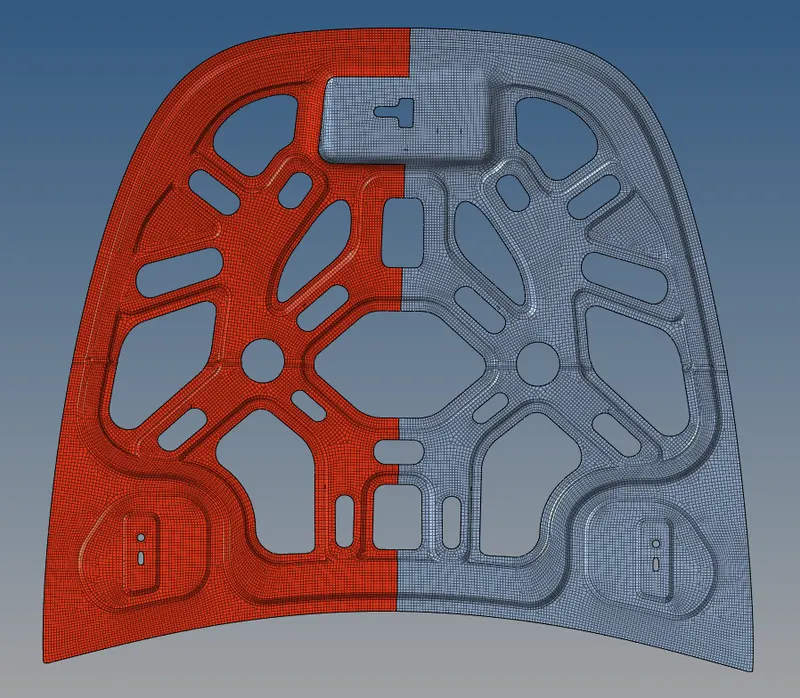
STEP 1I : PERFORM SYMMETRY OPERATION ON THE HALF OF THE INNER HOOD.
- To performing symmetry operation by reflect option in tools menu.
- Main menu > tools > reflect > selected the half portion of the inner hood elements > assigning the nodes,N1,N2,N3 &B > reflected it.
2D meshing of the inner hood
STEP 1J : PERFORMIING THE MODEL CHECKUP OF THE INNER HOOD.
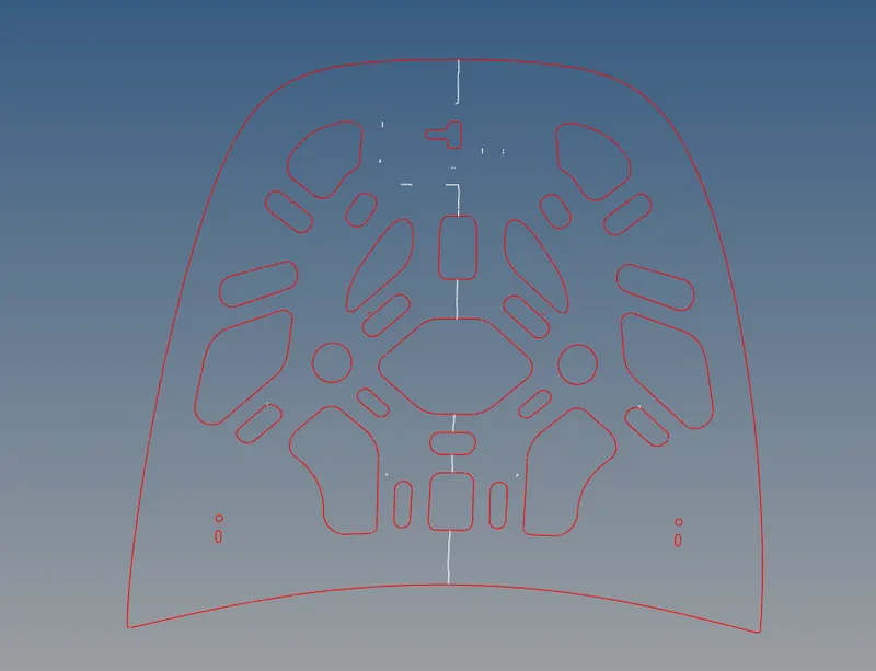
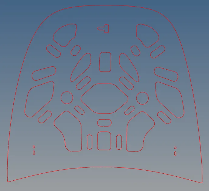
1.CHECK THE EDGES OF THE INNER HOOD
- After symmetry operation some of the edges was formed in between the elements
- Firstly check the edges are in the model by ,
- Mainmenu > tools > edges > selected the elements > set tolerance valueis 0.2 > run
- findout the unwanted edges in the elemets which are going to do preview equivalence and save equivalence it.
unwanted free edges was found fix the unwanted free edges
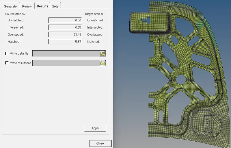
2.CHECK THE ElEMENTS CAPTURE INTO ENTIRE SURFACE OF THE INNER HOOD
- Title bar > mesh > check > elements > comparison > selected the source entities as a elements and selected the target entities as surfaces > tolerance=0.2 > run.
- Findout the red colored elements which are going to fix by mainmenu > tools > project > surface > selected the improper elements and its related surface > projected it.
All elements captured to the all surfaces
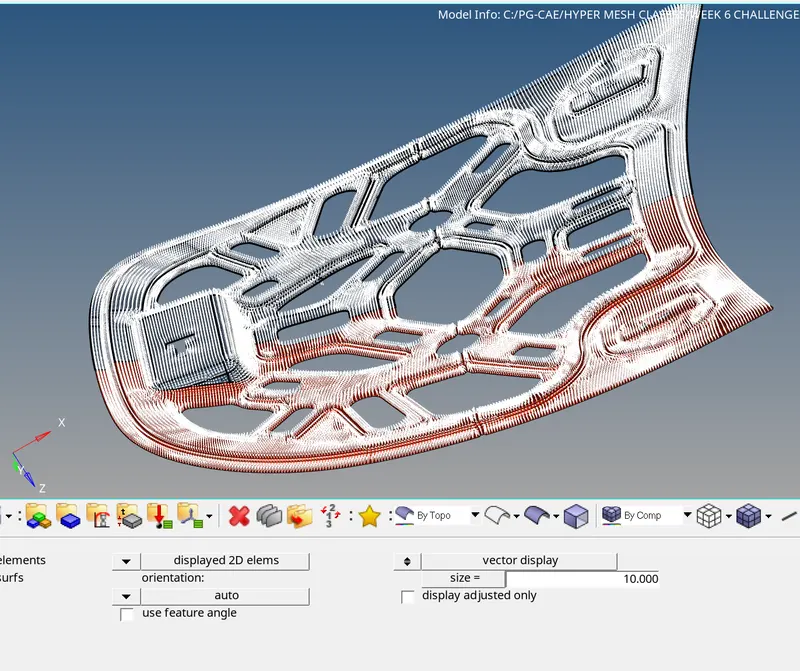
3.CHECK THE NORMALS TO THE SURFACE OF THE INNER HOOD
- Mainmenu > tools > normals > element > vector display , size=10units > display > reverse.
vector display of normals in inner.
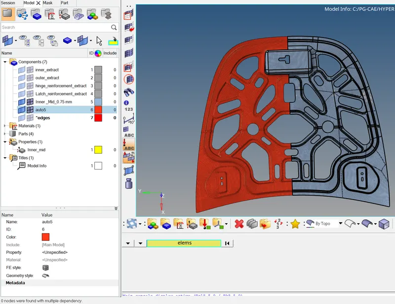
4.CHECK THE DEPENDENCY OF THE INNER HOOD
- Mainmenu > tools >dependency > selected the elements by display > click dependency.
- 0 nodes were found in the dependency .
Checked dependency of the inner hood
5.CHECK THE PENETRATION IN THE INNER HOOD
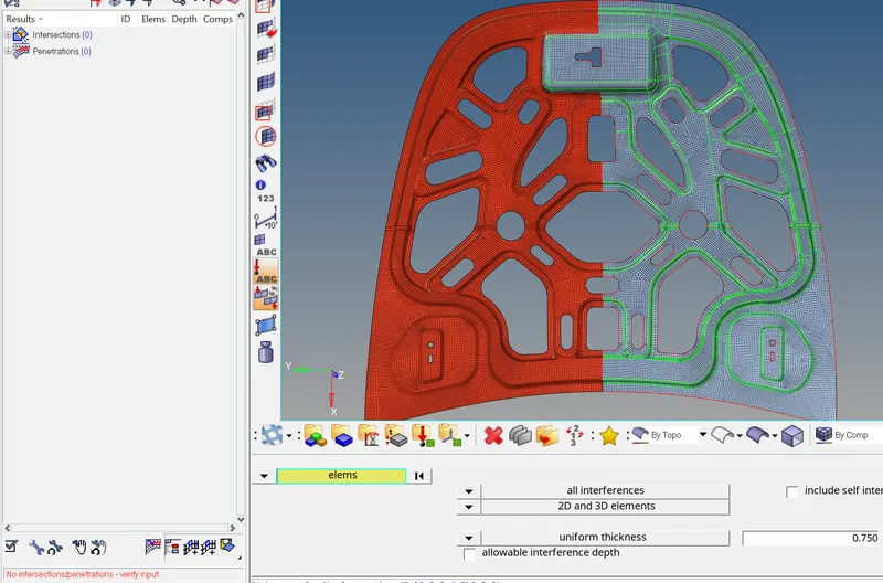
- Mainmenu > tools >penetration> selected the elements by display > set uniform thickness=0.75mm > click.
- No intersection and penetrations was not found.
Checked penetration in the inner hood.
PART 2 : 2D MESHING ON OUTTER BODY OF THE HOOD.
STEP 2A : GEOMETRICAL CHECKUP
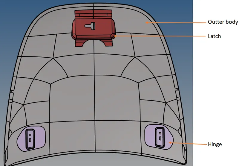
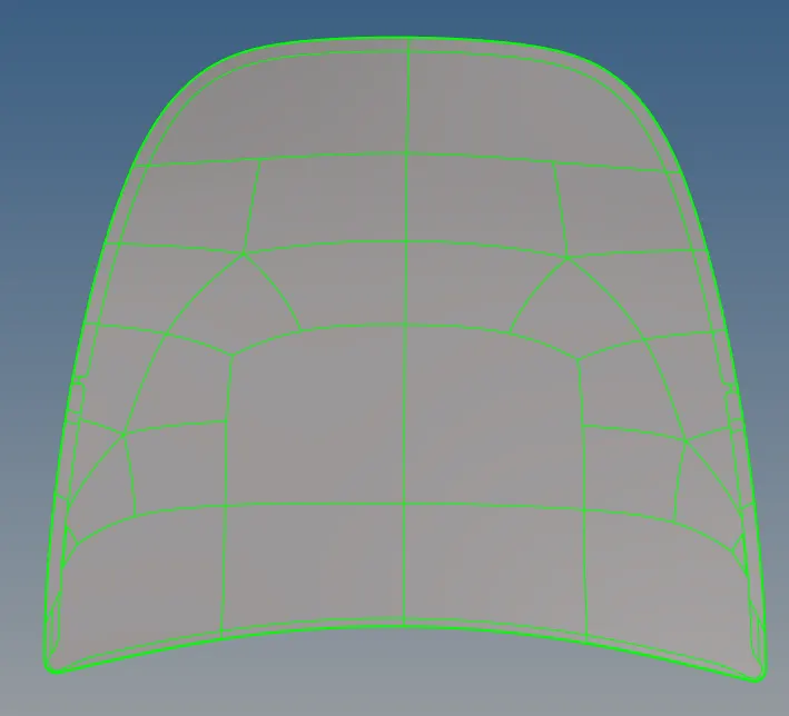
- Switch on the outter body only then,to check if there's any extra surface or free edges or missing surfaces are present or not. For this enable wireframe geometry mode and then try to observe and find irragularities and discontinuities in the model. If found then fix it manually.
Geometrical checkup on the outter hood
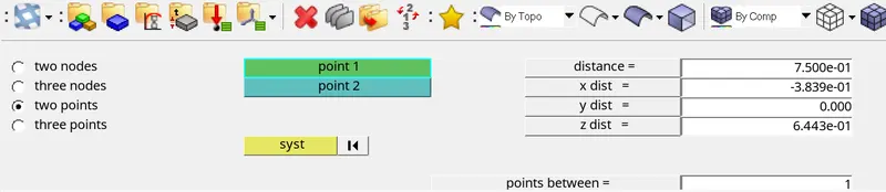
STEP 2B : THICKNESS MEASUREMENT ON THE OUTTER BODY OF THE HOOD.
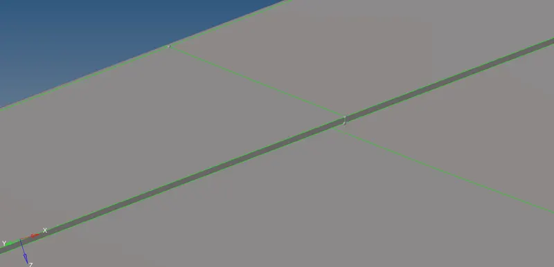
- Measured the thickness of the outter body of the hood by Geometry > distance > 2 points > selected the 2 points > distance measured is 0.75 mm
Mesured thickness of the outter body
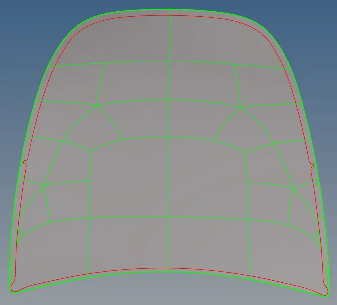
STEP 2C : MIDSURFACE EXTRACTION ON THE OUTTER BODY OF THE HOOD.
- Thickness of the outter body is uniform , so we choosed skin offset method for midsurface extraction.
- Midsurface extracted by Geometry > midsurface > extract option - skin offset > selected the all surfaces > extracted it.
Midsurface of the outter hood
STEP 2D : MATERIAL PROPERTIES AND THICKNESS ASSIGNING OF THE OUTTER HOOD.
- Then Created new property for outter hood, Set card image as a SHELL ,set the material as STEEL and assigning the thickness =0.75mm.
- Created material card and assigned material to the property card and then will assigned property card to outter hood midsurface component.
STEP 2E : IDENTIFY AND DELETING THE SYMMETRY SURFACES OF THE OUTTER HOOD
- Deleted the one side of the smmetry surfaces of the outter hood.
- Tools > delete > selected the one side of the symmetry surfaces > deleted it.
- Before go to the meshing toggled some lines in the geometry with below minimum length criteria.
- Mainmenu > geometry > toggle edge > selected the unmwanted lines > toggled it.
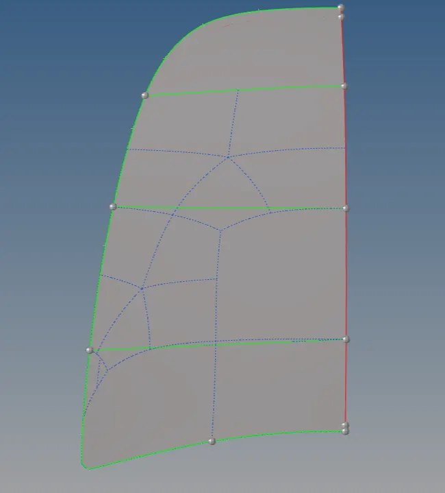
- Then the midsurface is splitted into 3 regions by, Mainmenu > geometry > surface edit > trim with nodes > splitted it.
- In hemming region , created the midline between fillet area by , Mainmenu > geometry > lines > midline > selected fillet area lines > created midline.
- Then,trim the midline with filler area by , Mainmenu > geometry > surface edit > trim with line option > selected the fillet surface and selected the midline > along vector > trimmed it.
Half portion of the outter hood midsurface
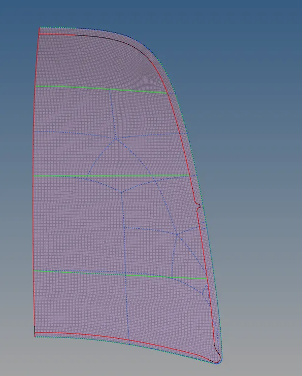
STEP 2F : 2D MESHING OF THE OUTTER HOOD
- Same procedure followed as the inner hood to achieve proper and uniform mesh flow.
2D meshing of half of the outter hood
STEP 2G : PERFORM SYMMETRY OPERATION ON THE HALF OF THE OUTTER HOOD.
- To performing symmetry operation by reflect option in tools menu.
- Main menu > tools > reflect > selected the half portion of the outter hood elements > assigning the nodes,N1,N2,N3 &B > reflected it.
2D meshing of full outter hood
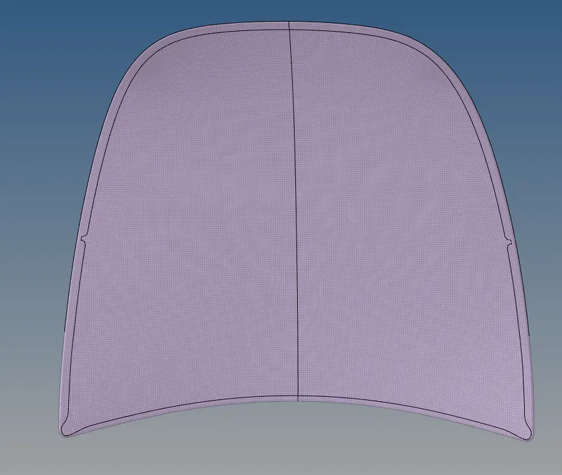
STEP 2H : CHECKING AND FIXING THE ELEMENTS FAILING FOR QUALITY .
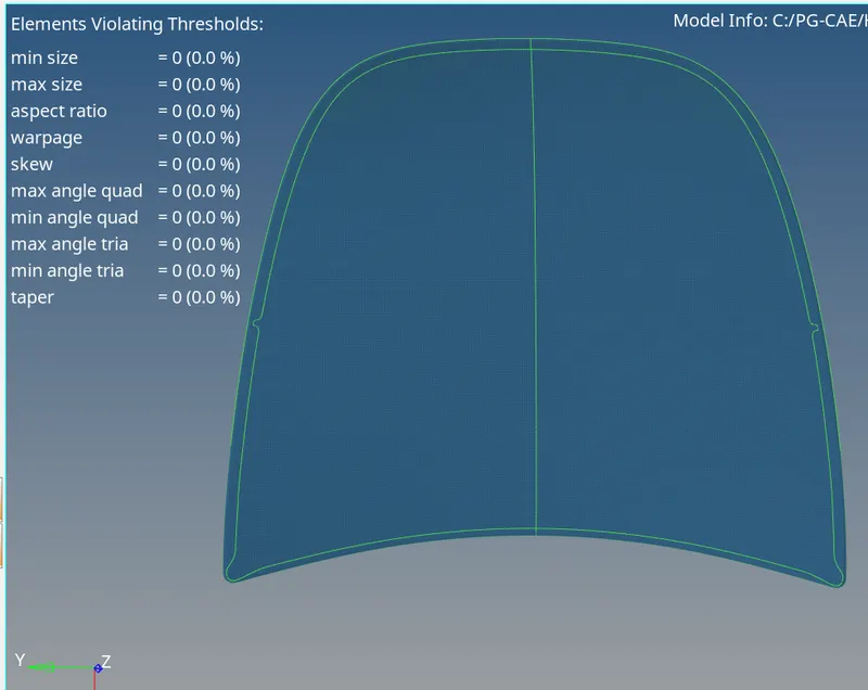
- Mainmenu > 2D > quality index > cleanup tools > set display threshold as fail > idenetified the elements which are failing for quality .
- Then , go to mainmenu > tools > check elements > 2D > set the quality criteria values a sper the geven data.
- Check the warpage quality by selected the elements which are failing for the warpage by save failed option.then go to mainmenu > tool > mask > selected the elements by retrieve > mask > reverse > showed the elements failing for warpage.
- Then go to the unmask adjacent option showed the adjacent elements, then its fixed by place node ,remesh, rebuild mesh options , element optimization and smooth in quality index.
5. Then fixed the elements which are failing for aspect ratio, min length , max length , skewness , taper , min & max angle trias and min & max angle quads.
After fixing the failing quality of outter hood
STEP 2I : PERFORMIING THE MODEL CHECKUP OF THE OUTTER HOOD.
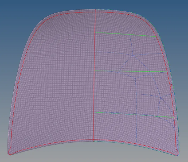
1.CHECK THE EDGES OF THE OUTTER HOOD
- After symmetry operation some of the edges was formed in between the elements
- Firstly check the edges are in the model by ,
- Mainmenu > tools > edges > selected the elements > set tolerance valueis 0.2 > run
- findout the unwanted edges in the elemets which are going to do preview equivalence and save equivalence it.
unwanted free edges was found fix the unwanted free edges
2.CHECK THE ElEMENTS CAPTURE INTO ENTIRE SURFACE OF THE OUTTER HOOD
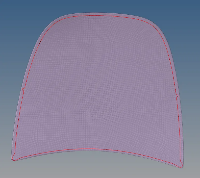
- Title bar > mesh > check > elements > comparison > selected the source entities as a elements and selected the target entities as surfaces > tolerance=0.2 > run.
- Findout the red colored elements which are going to fix by mainmenu > tools > project > surface > selected the improper elements and its related surface > projected it.
All elements captured to the all surfaces of the outter hood
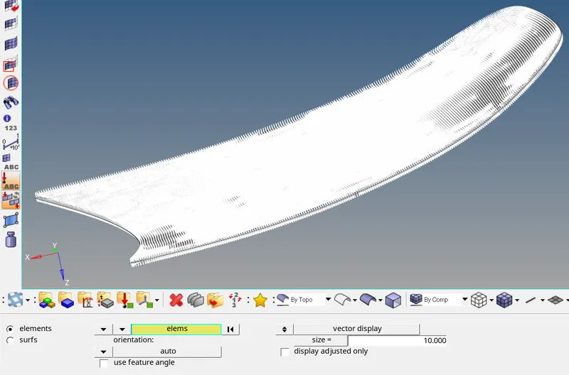
3.CHECK THE NORMALS TO THE SURFACE OF THE OUTTRR HOOD
- Mainmenu > tools > normals > element > vector display , size=15 units > display > reverse.
vector display of normals to outter.
4.CHECK THE DEPENDENCY OF THE OUTTER HOOD
- Mainmenu > tools >dependency > selected the elements by display > click dependency.
- 0 nodes were found in the dependency .
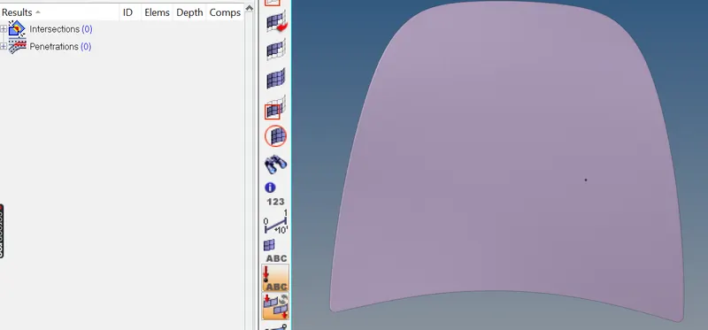
5.CHECK THE PENETRATION IN THE OUTTER HOOD
- Mainmenu > tools >penetration> selected the elements by display > set uniform thickness=0.75mm > click.
- No intersection and penetrations was not found.
Penetration checked in the outter
PART 3 : 2D MESHING ON HINGES OF THE HOOD.
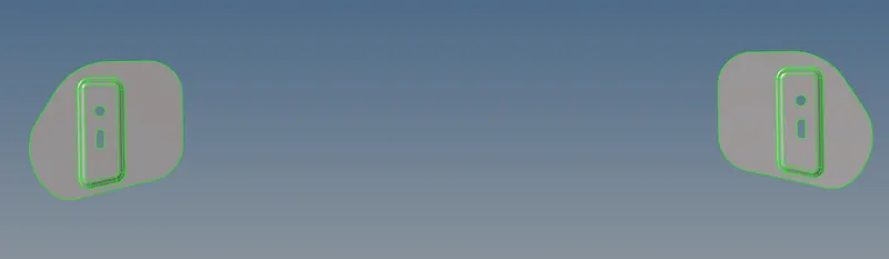
STEP 3A : GEOMETRICAL CHECKUP
- Switch on the hinges only then,to check if there's any extra surface or free edges or missing surfaces are present or not. For this enable wireframe geometry mode and then try to observe and find irragularities and discontinuities in the model. If found then fix it manually.
Geometrical checkup of the hinges
STEP 3B : THICKNESS MEASUREMENT ON THE HINGES OF THE HOOD.
- Measured the thickness of the hinges of the hood by Geometry > distance > 2 points > selected the 2 points > distance measured is 1.20 mm
Thickness measured of the hinges

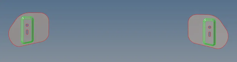
STEP 3C : MIDSURFACE EXTRACTION ON THE HINGES OF THE HOOD.
- Thickness of the hinges is uniform , so we choosed skin offset method for midsurface extraction.
- Midsurface extracted by Geometry > midsurface > extract option - skin offset > selected the all surfaces > extracted it.
- Before go to the meshing toggled some lines in the geometry with below minimum length criteria.
- Mainmenu > geometry > toggle edge > selected the unmwanted lines > toggled it.
Midsurface of the hinges
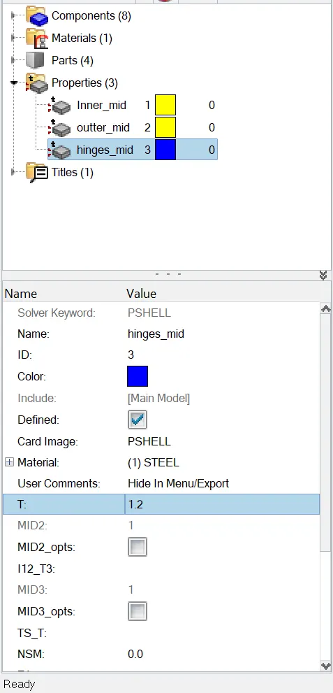
STEP 3D : MATERIAL PROPERTIES AND THICKNESS ASSIGNING OF THE HINGES.
- Then Created new property for hinges, Set card image as a SHELL ,set the material as STEEL and assigning the thickness =1.2 mm.
- Created material card and assigned material to the property card and then will assigned property card to hinges midsurface components.
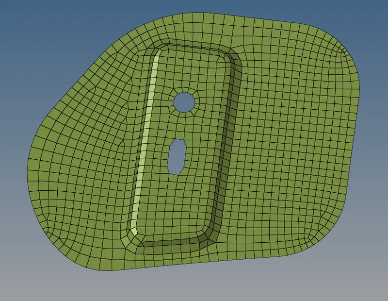
STEP 3E : 2D MESHING OF THE HINGES
- Same procedure followed as the inner hood and outter hood to achieve proper and uniform mesh flowin hinges.
2D meshing of hinge
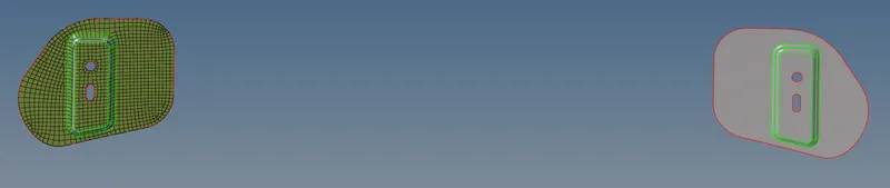
STEP3F : PERFORM SYMMETRY OPERATION ON THE HINGES
- To performing symmetry operation by reflect option in tools menu.
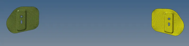
- Main menu > tools > reflect > selected the left side hinge elements > duplicate as a current component > y-axis reflect and selected symmetry node between the left side hinge and right side hinge> reflected it.
Before reflection of right side hinge
After reflection of right side hinge
STEP 3G : CHECKING AND FIXING THE ELEMENTS FAILING FOR QUALITY .
- Mainmenu > 2D > quality index > cleanup tools > set display threshold as fail > idenetified the elements which are failing for quality .
- Then , go to mainmenu > tools > check elements > 2D > set the quality criteria values a sper the geven data.
- Check the warpage quality by selected the elements which are failing for the warpage by save failed option.then go to mainmenu > tool > mask > selected the elements by retrieve > mask > reverse > showed the elements failing for warpage.
- Then go to the unmask adjacent option showed the adjacent elements, then its fixed by place node ,remesh, rebuild mesh options , element optimization and smooth in quality index.
5. Then fixed the elements which are failing for aspect ratio, min length , max length , skewness , taper , min & max angle trias and min & max angle quads.
After fixing the failing quality criterias of hinges.
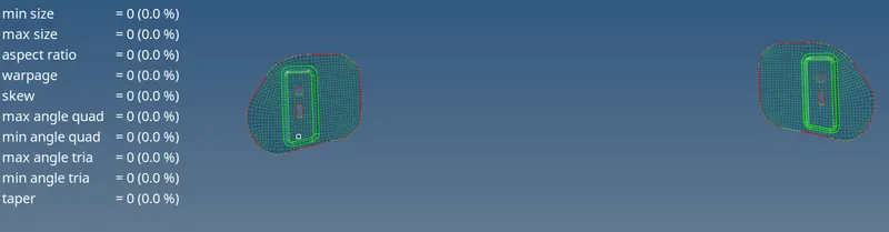
STEP 3H : PERFORMIING THE MODEL CHECKUP OF THE HINGES.
1.CHECK THE EDGES OF THE HINGES
- After symmetry operation some of the edges was formed in between the elements
- Firstly check the edges are in the model by ,
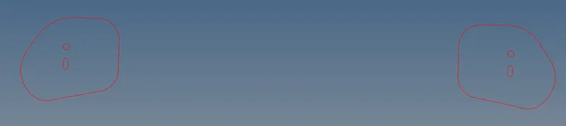
- Mainmenu > tools > edges > selected the elements > set tolerance valueis 0.5 > run
- findout the unwanted edges in the elemets which are going to do preview equivalence and save equivalence it.
No free edges formed in between the elements
2.CHECK THE ElEMENTS CAPTURE INTO ENTIRE SURFACE OF THE HINGES
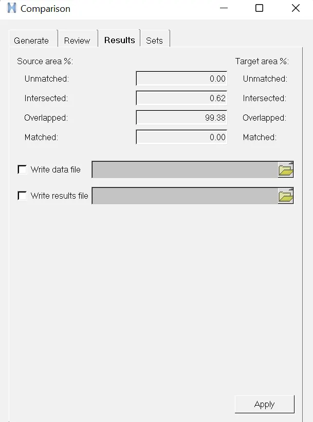
- Title bar > mesh > check > elements > comparison > selected the source entities as a elements and selected the target entities as surfaces > tolerance=0.2 > run.
- Findout the red colored elements which are going to fix by mainmenu > tools > project > surface > selected the improper elements and its related surface > projected it.
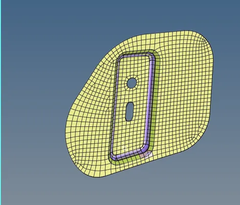
All elements are captured properly to the all surfaces of the hinges
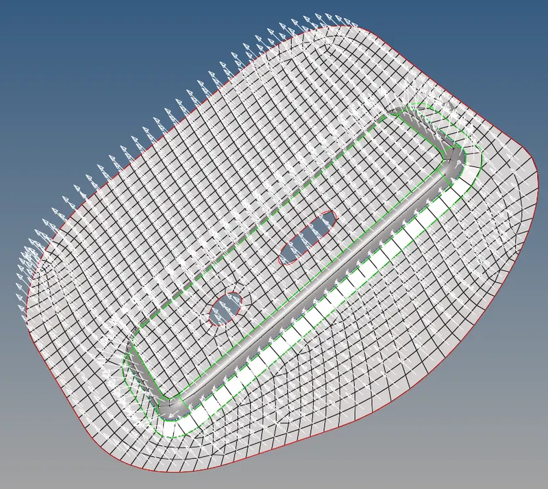
3.CHECK THE NORMALS TO THE SURFACE OF THE HINGES
- Mainmenu > tools > normals > element > vector display , size=10 units > display > reverse.
vector display of normals to the hinges.
4.CHECK THE DEPENDENCY OF THE HINGES
- Mainmenu > tools >dependency > selected the elements by display > click dependency.
- 0 nodes were found with multiple dependency.
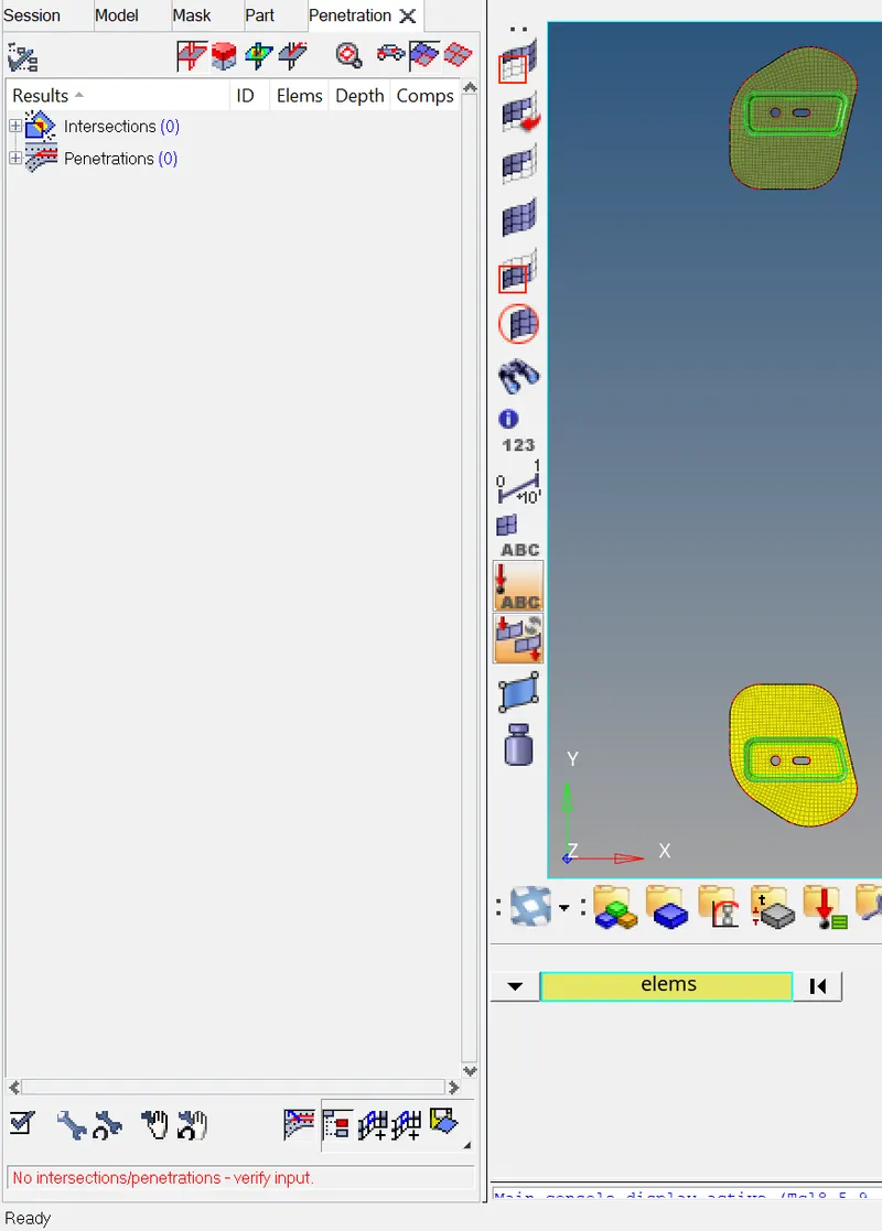
5.CHECK THE PENETRATION IN THE HINGES
- Mainmenu > tools >penetration> selected the elements by display > set uniform thickness=1.2 mm > click.
- No intersection and penetrations was not found.
PART 4 : 2D MESHING ON LATCH OF THE HOOD.
STEP 4A : GEOMETRICAL CHECKUP
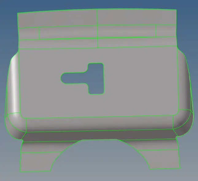
- Switch on the latch only then,to check if there's any extra surface or free edges or missing surfaces are present or not. For this enable wireframe geometry mode and then try to observe and find irragularities and discontinuities in the model. If found then fix it manually.
Geometrical checkup of the latch
STEP 4B : THICKNESS MEASUREMENT ON THE LATCH OF THE HOOD.
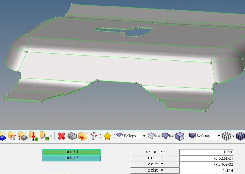
- Measured the thickness of the latch of the hood by Geometry > distance > 2 points > selected the 2 points > distance measured is 1.20 mm
Measured thickness of the latch
STEP 4C : MIDSURFACE EXTRACTION ON THE LATCH OF THE HOOD.
- Thickness of the latch is uniform , so we choosed skin offset method for midsurface extraction.
- Midsurface extracted by Geometry > midsurface > extract option - skin offset > selected the all surfaces > extracted it.
- Before go to the meshing toggled some lines in the geometry with below minimum length criteria.
- Mainmenu > geometry > toggle edge > selected the unmwanted lines > toggled it.
Midsurface of latch
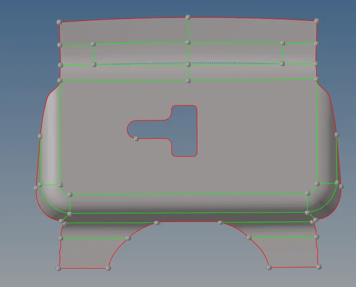
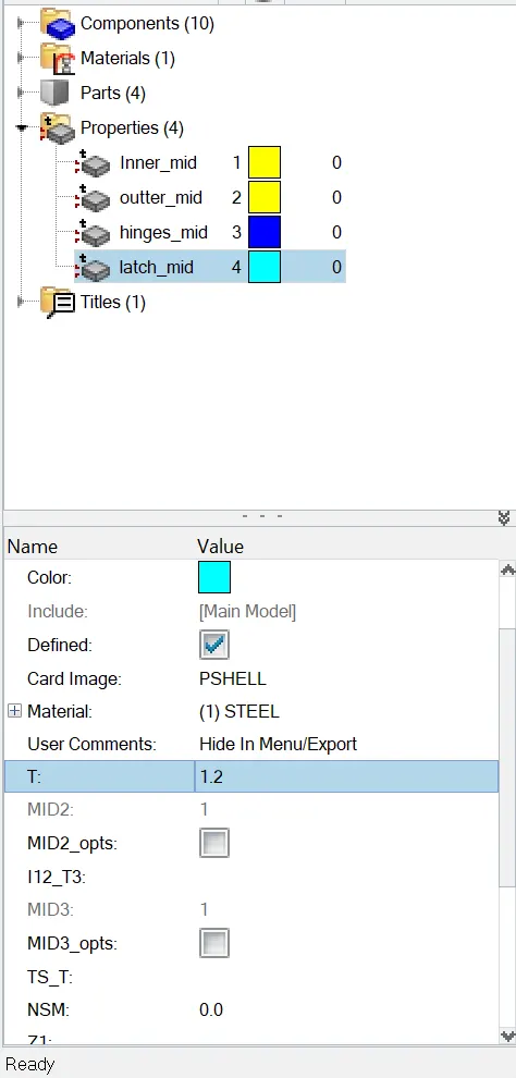
STEP 4D : MATERIAL PROPERTIES AND THICKNESS ASSIGNING OF THE LATCH.
- Created new property for latch, Set card image as a SHELL ,set the material as STEEL and assigning the thickness =1.2 mm.
- Created material card and assigned material to the property card and then will assigned property card to latch midsurface components.
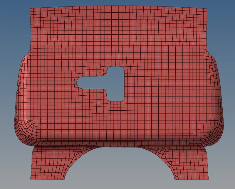
STEP 4E : 2D MESHING OF THE LATCH
- Same procedure will followed as the inner hood ,outter hood and hinges to achieve proper and uniform mesh flow as in latch.
2D meshing of latch
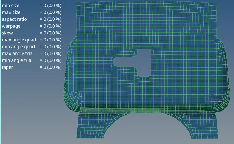
STEP 4F : CHECKING AND FIXING THE ELEMENTS FAILING FOR QUALITY .
- Mainmenu > 2D > quality index > cleanup tools > set display threshold as fail > idenetified the elements which are failing for quality .
- Then , go to mainmenu > tools > check elements > 2D > set the quality criteria values a sper the geven data.
- Check the warpage quality by selected the elements which are failing for the warpage by save failed option.then go to mainmenu > tool > mask > selected the elements by retrieve > mask > reverse > showed the elements failing for warpage.
- Then go to the unmask adjacent option showed the adjacent elements, then its fixed by place node ,remesh, rebuild mesh options , element optimization and smooth in quality index.
5. Then fixed the elements which are failing for aspect ratio, min length , max length , skewness , taper , min & max angle trias and min & max angle quads.
After fixing the failing quality criterias of latch.
STEP 3H : PERFORMIING THE MODEL CHECKUP OF THE LATCH.
1.CHECK THE EDGES OF THE LATCH
- Firstly check the edges are in the model by ,
- Mainmenu > tools > edges > selected the elements > set tolerance valueis 0.2 > run
- findout the unwanted edges in the elemets which are going to do preview equivalence and save equivalence it.
No free edges formed in between the elements
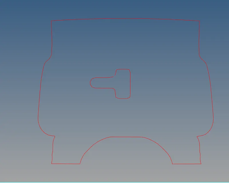
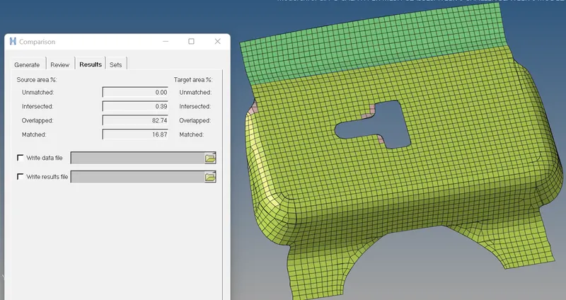
2.CHECK THE ElEMENTS CAPTURE INTO ENTIRE SURFACE OF THE LATCH
- Title bar > mesh > check > elements > comparison > selected the source entities as a elements and selected the target entities as surfaces > tolerance=0.2 > run.
- Findout the red colored elements which are going to fix by mainmenu > tools > project > surface > selected the improper elements and its related surface > projected it.
Elements are captured properly to the all surfaces of the latch
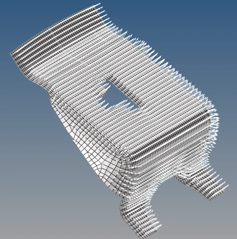
3.CHECK THE NORMALS TO THE SURFACE OF THE LATCH
- Mainmenu > tools > normals > element > vector display , size=10 units > display > reverse.
vector display of normals of the latch.
4.CHECK THE DEPENDENCY OF THE LATCH
- Mainmenu > tools >dependency > selected the elements by display > click dependency.
- 0 nodes were found with multiple dependency.
5.CHECK THE PENETRATION IN THE LATCH
- Mainmenu > tools >penetration> selected the elements by display > set uniform thickness=1.2 mm > click.
- No intersection and penetrations was not found.
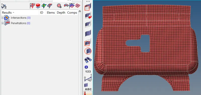
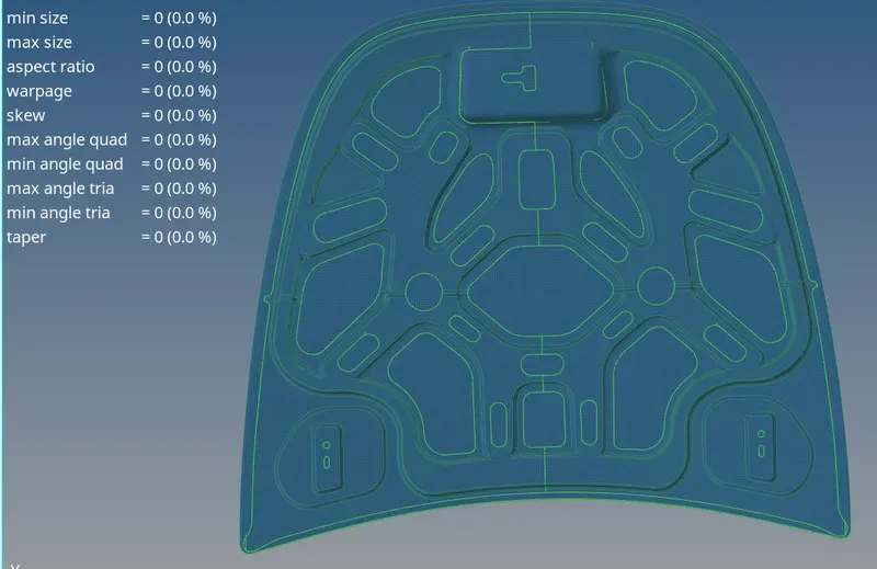
FINAL FE MODEL OF THE AUTOMOTIVE HOOD IN 3D REPRESENTATION WITH NO QUALITY ERRORS
RESULT :
- Hence the geometric cleanup of the hood without any free edges was successfully completed.
- Then extracted the midsurface successfully from the parent IP geometry.
- Then fixed the damaged geometry in the midsurface.
- A well connectivity established between the surfaces.
- The features have been captured properly.
- Performed 2D meshing of hood with no quality issues.
- Performed model checkup on the hood successfully.
LEARNING OUTCOMES :
- In this week6 challenge, i came to know
- How to do geometric cleanup of the part without any free edges.
- How to do extract the midsurface by skin method .
- How to do fixing the damaged geometry in the midsurface
- How to do uniform and proper mesh flow in 2D meshing process.
- How to do fix the elements which are failing for quality.
- how to do model checkup of the final FE model.