Project - 2 - Meshing on the suspension Assembly
SHELL AND SOLID MESHING OF AN AUTOMOTIVE REAR SUSPENSION ASSEMBLY
AIM :
- To perform shell and solid meshing of an rear suspension assembly.
- To deploy connections in necessary regions.
OBJECTIVE :
- To do geometry cleanup on the component.
- To extract a midsurface of the components, if the thickness is less than 5 mm
- Performing shell mesh with the mixed element type for the components having less than
5mm thickness. - Performing shell mesh with the tria element type and creating a volume mesh for the
components having more than 5mm thickness. - Deploying bolt and seam weld connections in required regions.
- Representing coil spring with CBAR 1D Element.
- Performing symmetric operation.
SOFTWARE USED :
Preprocessing software - ANSA V22.1.1
DATA BASE:
THEORETICAL FRAME WORK:
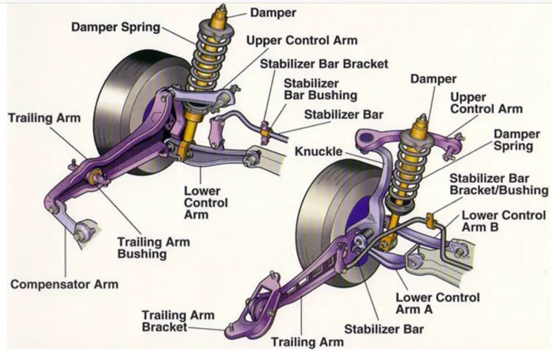
Automotive Rear suspension system
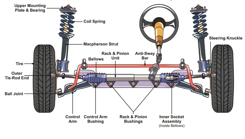
Automotive Rear suspension system overall assembly
SUSPENSION :
1. Suspension is the system of tires, tire air, springs, shock absorbers and linkages that
connects a vehicle to its wheels and allows relative motion between the two.
2. Suspension systems must support both road holding/handling and ride quality, which are
at odds with each other. The tuning of suspensions involves finding the right compromise.
3. It is important for the suspension t keep the road wheel in contact with the road surface as much as possible,because all the road or ground forces acting on the vehicle do so through the contact patches of the tires.
4 .The suspension also protects the vehicle itself and any cargo or luggage from damageand wear. The design of front and rear suspension of a car may be different.
REAR SUSPENSION :
1.The rear suspension of a vehicle performs the same general function as front suspension,but the specific construction is typically quite different.
2.The suspension must be able to handle the transfer of engine torque effectively to the wheels while resisting the rotational
force of the driveshaft.
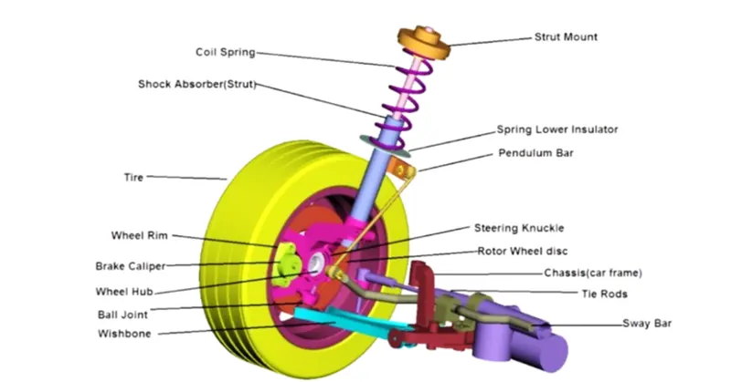
COMPONENETS NAMES IN SUSPENSION :
PROCEDURAL STEPS:
STEP 1 : Importing the CAD model of a ansa file of Automotive rear suspension assembly .
Without TOPO of suspension assembly
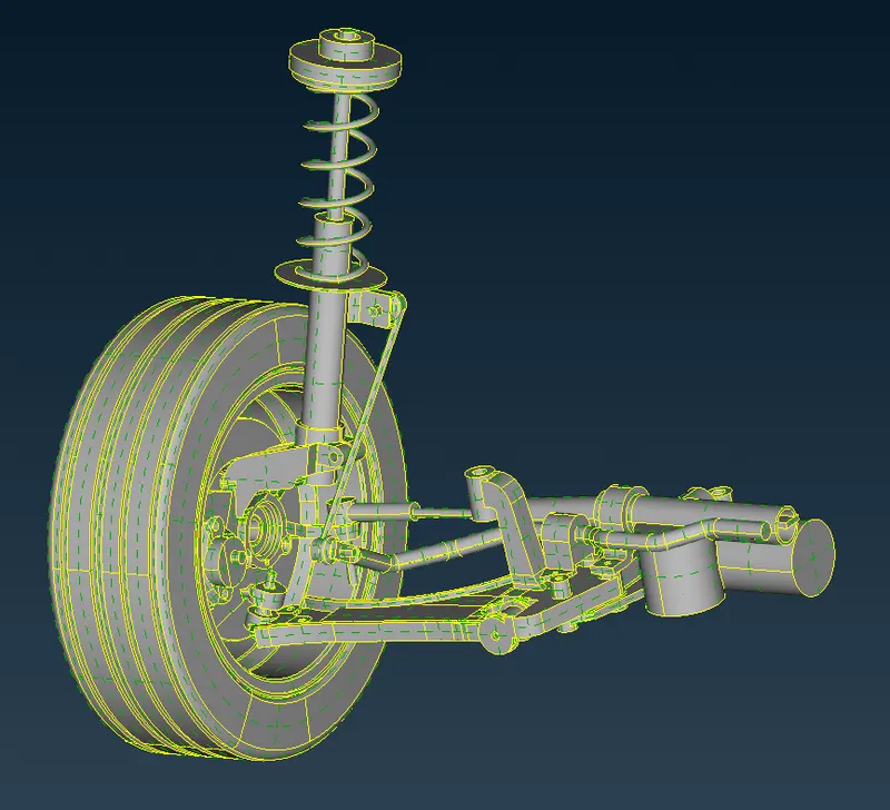
STEP 2 : Use INOT option to separate every parts .
In each parts are performed to increase the cons resolutiion by MESH MODULE > PERIMETER > LENGTH =1mm
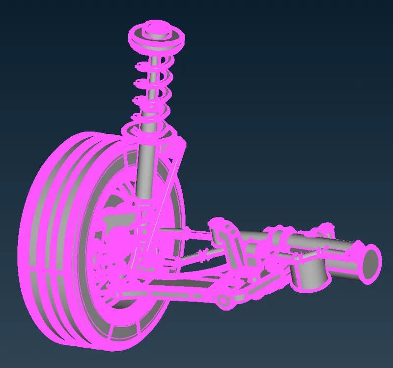
STEP 3 : Each parts are performed topo to get the connectivity between the surfaces.
TOPO MODULE > FACES > TOPO .
With TOPO of suspension assembly
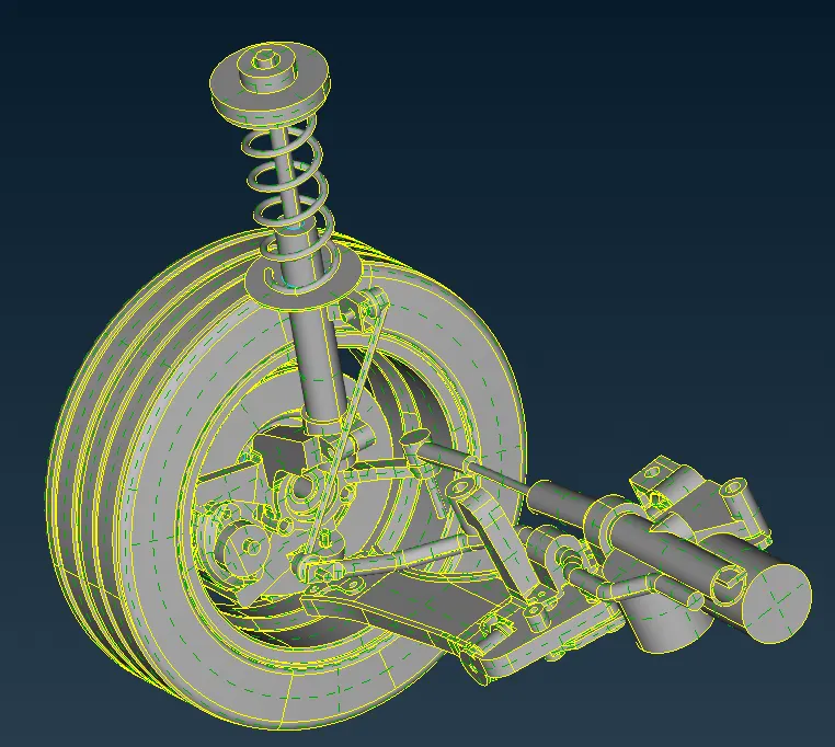
STEP 4 : Each parts are performed orientation operation to make sure all surfaces are in one direction .
TOPO MODULE > FACES > ORIENT.
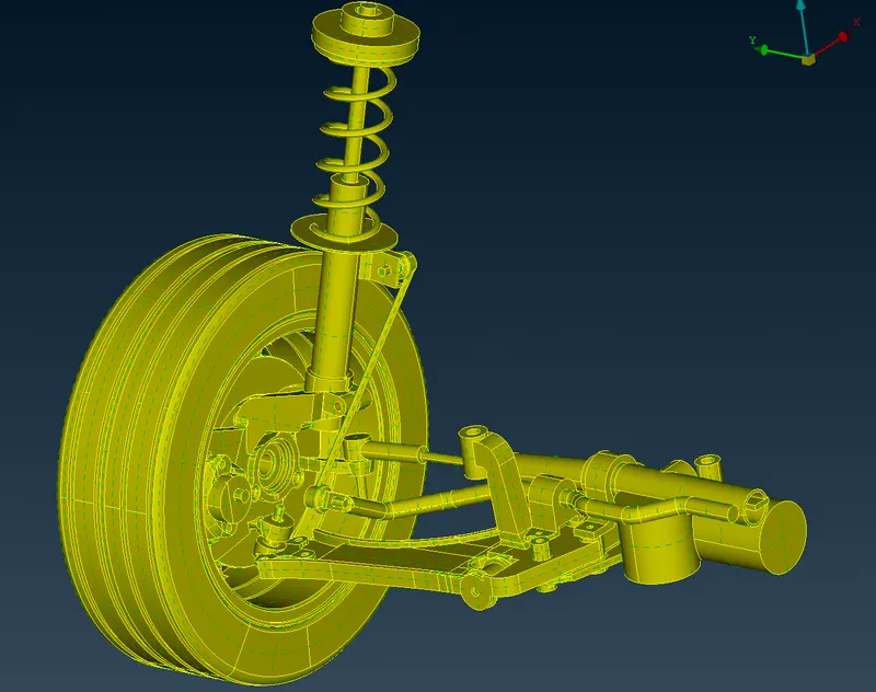
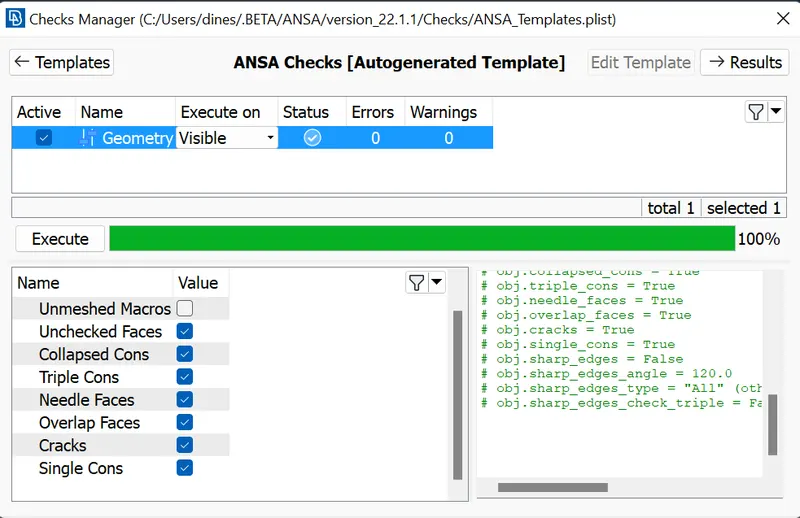
STEP 5 : Each parts are checking geometrical errors and clearing the errors.
CHECKS > CHECK MANAGER > click undefined materials
CHECKS > CHECK GEOMETRY > fixed the errors by manual and automatic method.
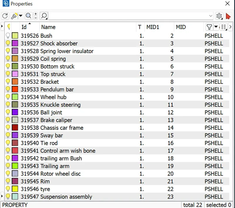
STEP 6 : To created separate PIDs for each and every components in the rear suspension assembly.
STEP 7 : PART 1 - SPRING LOWER INSULATOR
STEP 7A: EXTRACT MIDSURFACE OF AN SPRING LOWER INSULATOR.
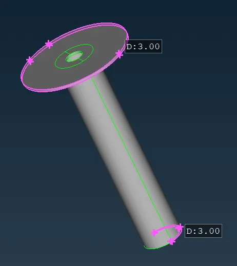
1. To measured the thickness of the spring lower insulator .
2. Thickness is 3 mm uniform throughout
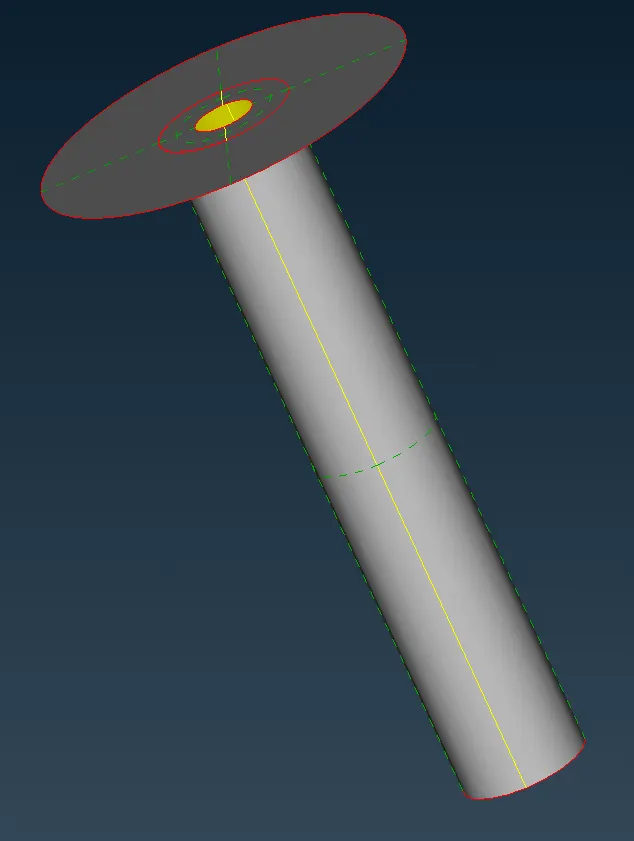
3. To extract the midsurface of the spring lower insulator by TOPO MODULE > FACES > OFFSET > faces - selected the faces to offset by 1.5mm
Measured thickness of an spring insulator
Midsurface of an spring insulator
STEP 7B : SHELL MESHING OF AN SPRING LOWER INSULATOR
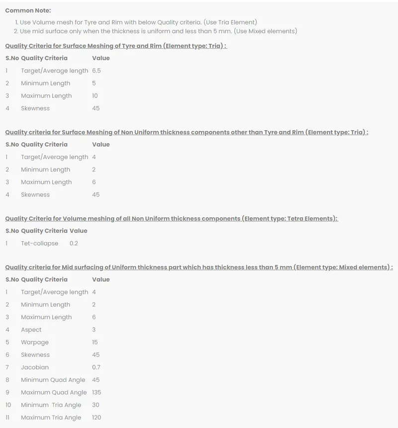
Set the quality criteria and mesh parameter as per the given data for quality criteria for midsurfacing of uniform thickness part which has thickness less than 5mm
1. Before go to the meshing, set the target element length value is 4 mm.
2. MESH MODULE > PERIMETER > LENGTH =4mm
3. MESH MODULE > MESH GENERATION > BEST selected the Element type : Mixed.
4. Meshing Done.
5. Cleared the elements which are failing for quality .
6. Assigned the proper orientation to the elements.
7. Assigned the proper thickness for the newly created midsurface.
8. Released the FE from the geometry.
Shell mesh of an spring lower insulator
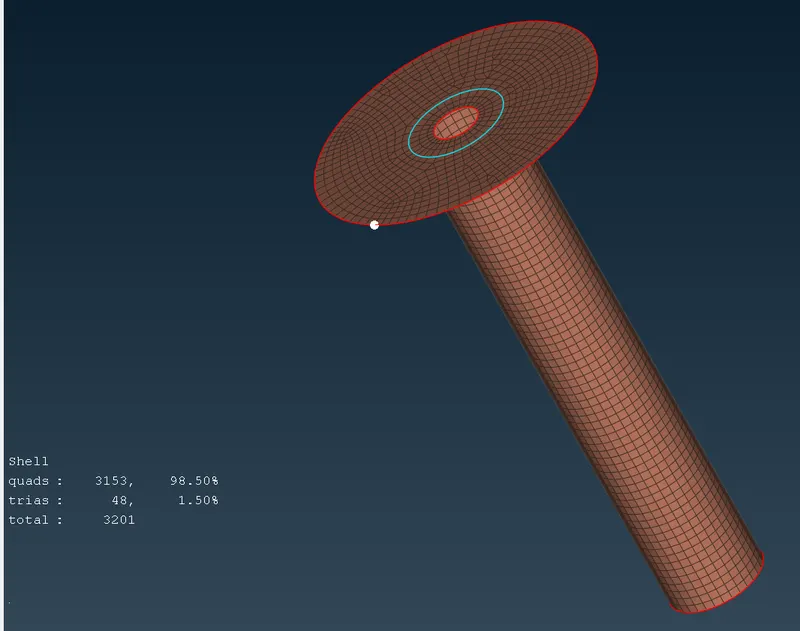
STEP 7C : Draw shell as a solid of an spring lower insulator
1. To convert 2D into 3D ,in presentation parameters set the draw shell as solid of an spring lower insulator.
3D meshing of an spring insulator.
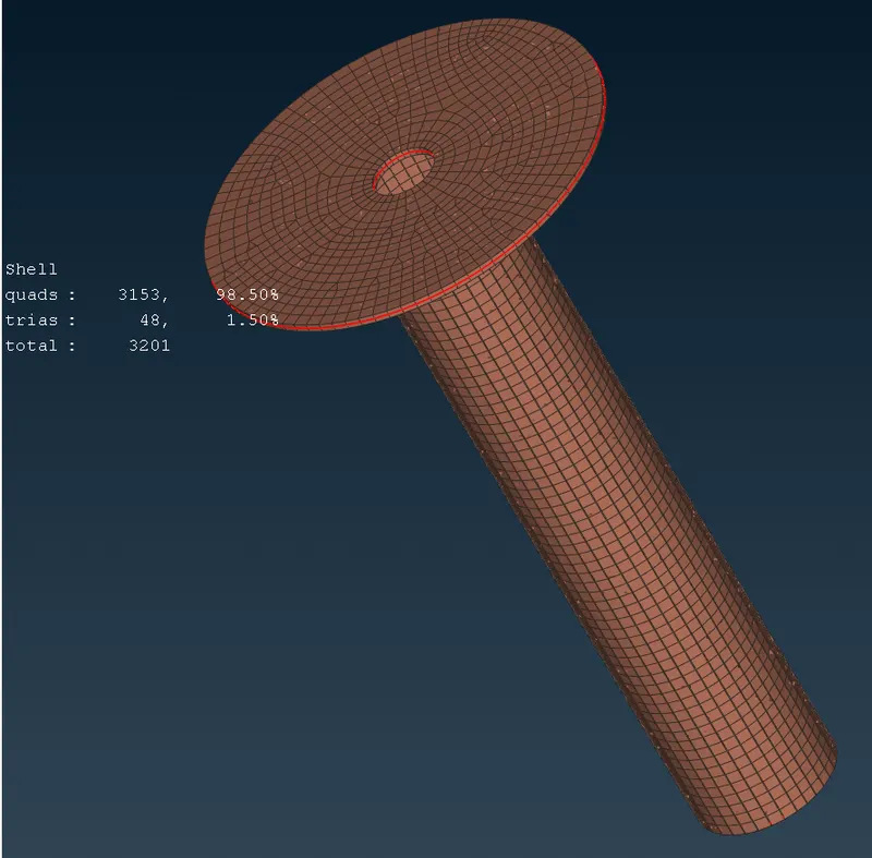
STEP 8 : PART 2 - BRACKET
STEP 8A : EXTRACT MIDSURFACE OF AN BRACKET.
1. To measured the thickness of the bracket .
2. Thickness is 3 mm uniform throughout
3. To extract the midsurface of the bracket by TOPO MODULE > MIDSURFACE > SKIN > to selected the faces to offset by 1.5mm.
Measured thickness of an Bracket
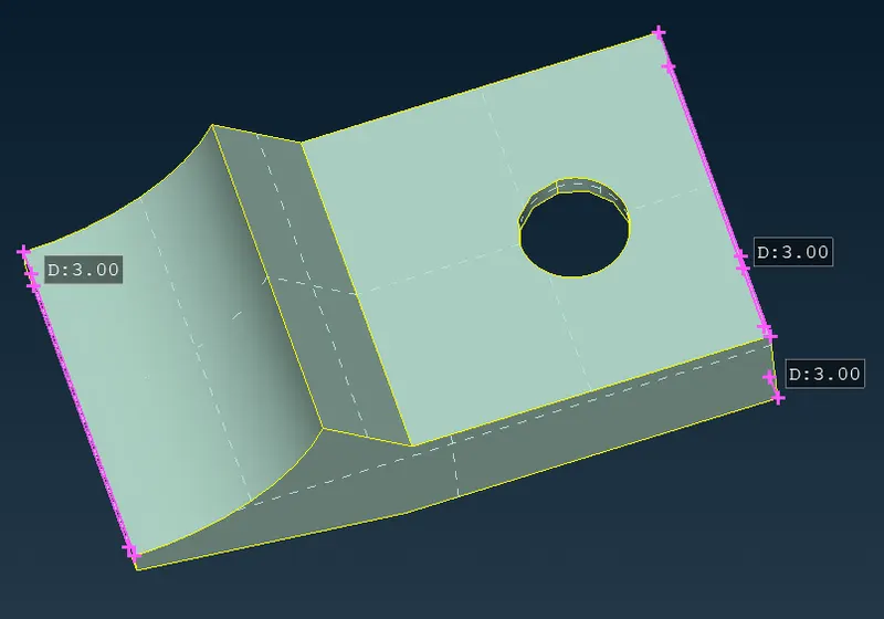
Midsurface of an Bracket
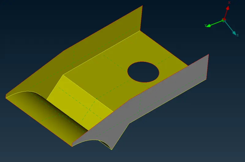
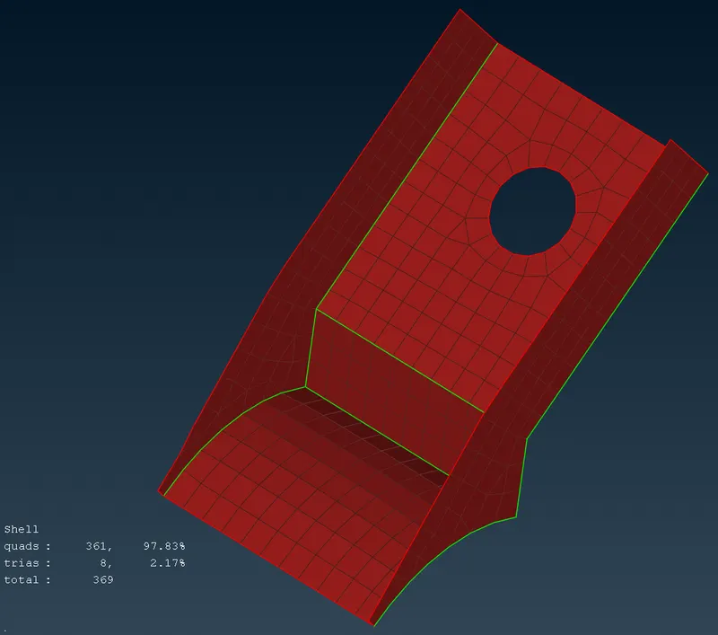
STEP 8B : SHELL MESHING OF AN SPRING LOWER INSULATOR
Set the quality criteria and mesh parameter as per the given data for quality criteria for midsurfacing of uniform thickness part which has thickness less than 5mm
1. Before go to the meshing, set the target element length value is 4 mm.
2. MESH MODULE > PERIMETER > LENGTH =4mm
3. MESH MODULE > MESH GENERATION > BEST selected the Element type : Mixed.
4. Meshing Done.
5. Cleared the elements which are failing for quality .
6. Assigned the proper orientation to the elements.
7. Assigned the proper thickness for the newly created midsurface.
8. Released the FE from the geometry.
Shell mesh of an Bracket
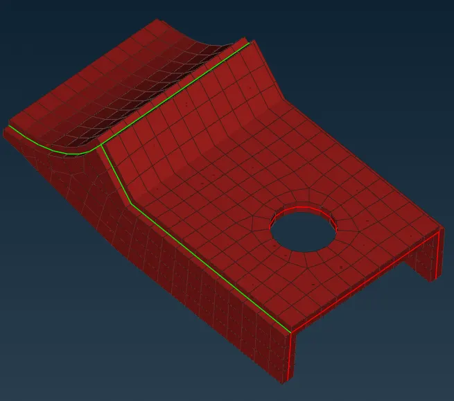
STEP 8C : DRAW SHELL AS A SOLID OF AN BRACKET
1. To convert 2D into 3D ,in presentation parameters set the draw shell as solid of an spring lower insulator.
STEP 9 : PART 3 - CONTROL ARM WISHBONE
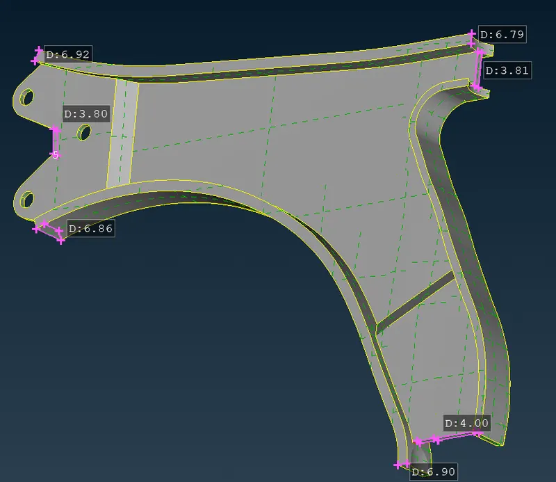
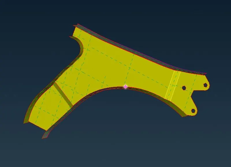
STEP 9A : EXTRACT MID SURFACE OF AN CONTROL ARM WISHBONE
1. To measured the thickness of the control arm wishbone
2. Thickness is varying from part to part.
3. To extract the midsurface of the bracket by TOPO MODULE > FACES > OFFSET by the individual varying thickness part.
4. Create individual PIDs for those parts.
Measured thickness of an wishbone
Midsurface of an wishbone
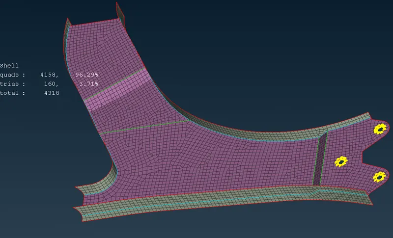
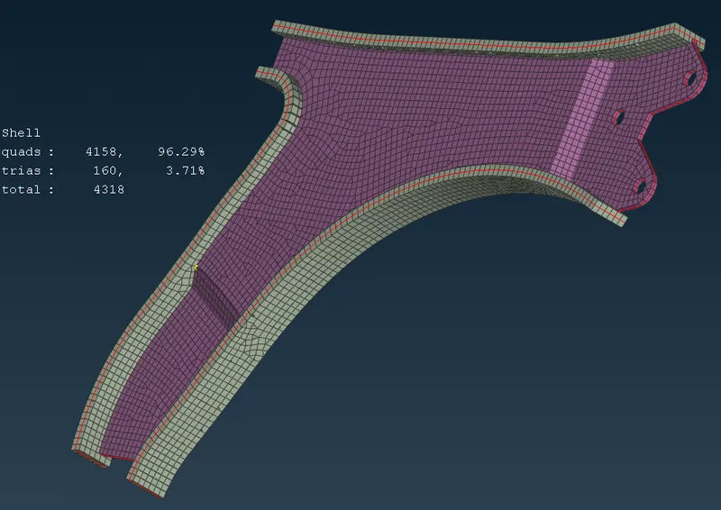
STEP 9 B : SHELL MESHING OF AN CONTROL ARM WISHBONE
Set the quality criteria and mesh parameter as per the given data for quality criteria for midsurfacing of Non uniform thickness components.
1. Before go to the meshing, set the target element length value is 4 mm.
2. MESH MODULE > PERIMETER > LENGTH =4mm
3. MESH MODULE > MESH GENERATION > BEST selected the Element type : Mixed.
4. Meshing Done.
5. Cleared the elements which are failing for quality .
6. Assigned the proper orientation to the elements.
7. Assigned the proper thickness for the newly created midsurface.
8. Released the FE from the geometry.
9.To convert 2D into 3D ,in presentation parameters set the draw shell as solid.
Shell mesh of an control arm wishbone
STEP 10 : PART 4 - CONTROL ARM WISHBONE BUSH ONE
STEP 10 A : EXTRACT MID SURFACE OF AN CONTROL ARM WISHBONE BUSH ONE
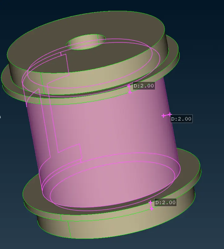
1. To measured the thickness of the control arm wishbone
2. Thickness is uniform
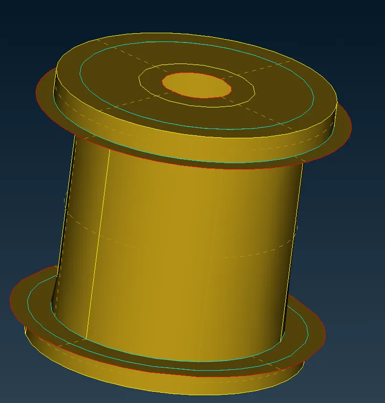
3. To extract the midsurface of the bracket by TOPO MODULE > FACES > OFFSET =1 mm
Measured thickness of an wishbone bush one
Midsurface of an wishbone bush one
STEP 10 B : SHELL MESHING OF AN CONTROL ARM WISHBONE BUSH 1
Set the quality criteria and mesh parameter as per the given data for quality criteria for midsurfacing of uniform thickness components.
1. Before go to the meshing, set the target element length value is 4 mm.
2. MESH MODULE > PERIMETER > LENGTH =4mm
3. MESH MODULE > MESH GENERATION > BEST selected the Element type : Mixed.
4. Meshing Done.
5. Cleared the elements which are failing for quality .
6. Assigned the proper orientation to the elements.
7. Assigned the proper thickness for the newly created midsurface.
8. Released the FE from the geometry.
9.To convert 2D into 3D ,in presentation parameters set the draw shell as solid.
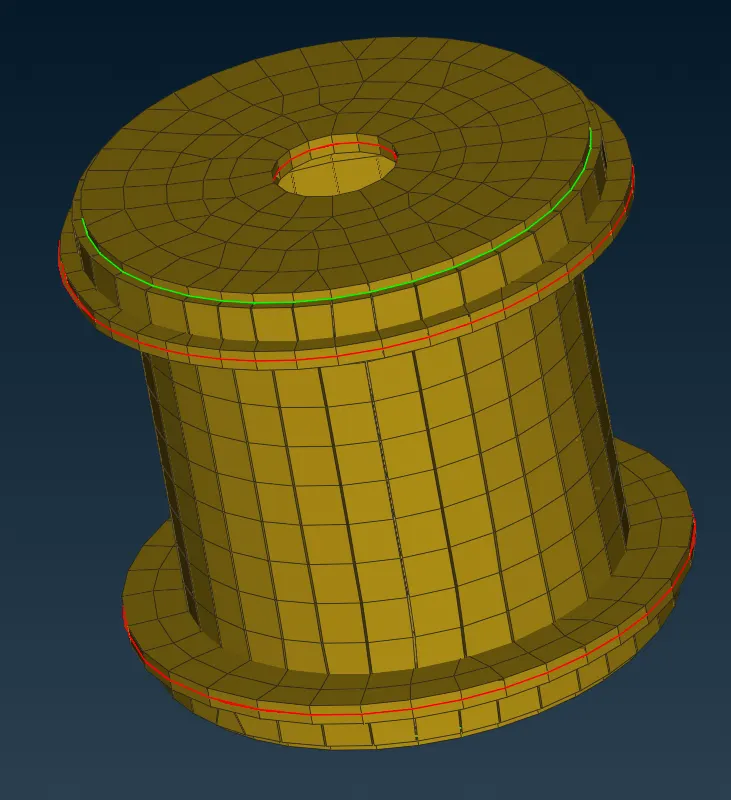
Shell mesh of an control arm wishbone bush one
STEP 11 : PART 5 - CONTROL ARM WISHBONE BUSH TWO
same as the above procedure of bush one.
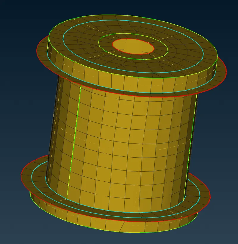
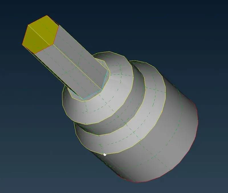
Midsurface of an wishbone bush two
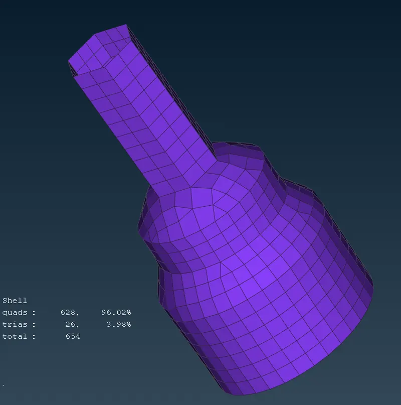
Shell mesh of an control arm wishbone bush two
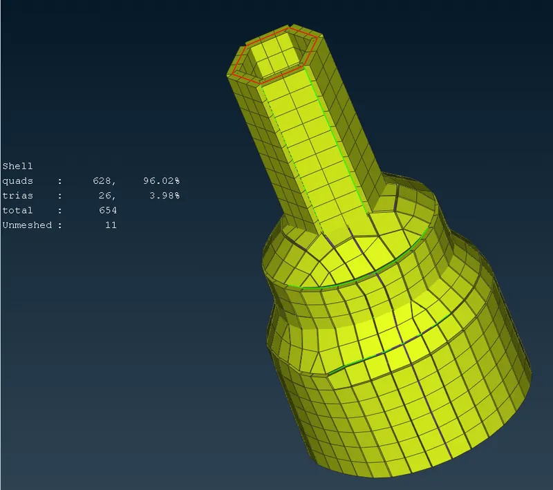
STEP 12 : PART 6 - SURFACE MESHING AND VOLUME MESHING OF AN TYRE
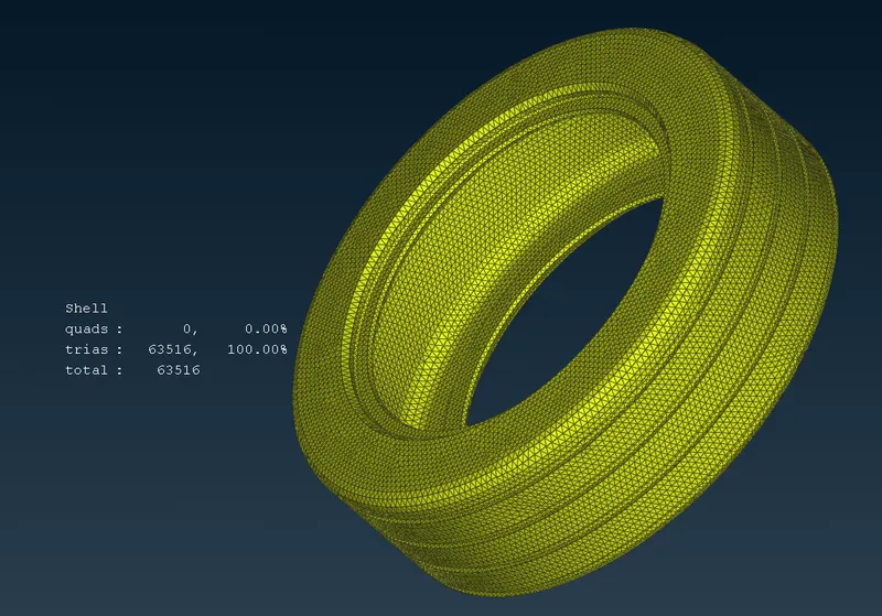
1. Set the quality criteria and mesh parameter as per the given data for quality criteria for suurface meshing of tyre and Rim .
2. Provided the Target element length by MESH MODULE > PERIMETER > LENGTH = 6.5 mm.
3. MESH MODULE > MESH GENERATION > BEST selected the Element type : Curved Area-Ortho Tria
Flat Area - Tria.
4. Surface Meshing Done.
5. Cleared the elements which are failing for quality .
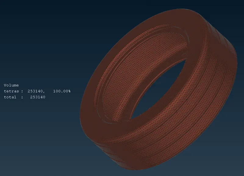
6. Before starting the volume mesh, set the quality criteria of the non uniform thickness components. TET collapse-0.2mm
7. Then go to Volume Mesh > Define > the selected tyre part
Volume Mesh > List > Auto detected volume > edit > Rapid tetra then remeshed it.
8. Volume Meshing done.
9. Cleared the elements whicha are falling for TET collapse.
Surface meshing of a tyre
Volume meshing of a tyre
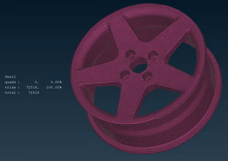
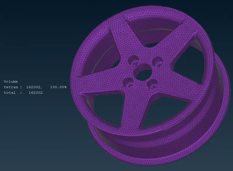
STEP 13 : PART 7 - SURFACE MESHING AND VOLUME MESHING OF RIM.
Same procedure followed by an Surface meshing and solid meshing of rim.
Surface meshing of rim
Volume meshing of rim
STEP 14 : PART 8 - SURFACE MESHING AND VOLUME MESHING OF ROTOR WHEEL DISC.
1. Set the quality criteria and mesh parameter as per the given data for quality criteria for surface meshing of non uniform thickness components
2. Provided the Target element length by MESH MODULE > PERIMETER > LENGTH = 4 mm.
3. MESH MODULE > MESH GENERATION > BEST selected the Element type : Curved Area-Ortho Tria
Flat Area - Tria.
4. Surface Meshing Done.
5. Cleared the elements which are failing for quality .
6. Before starting the volume mesh, set the quality criteria of the non uniform thickness components. TET collapse-0.2mm
7. Then go to Volume Mesh > Define > the selected part
Volume Mesh > List > Auto detected volume > edit > Rapid tetra then remeshed it.
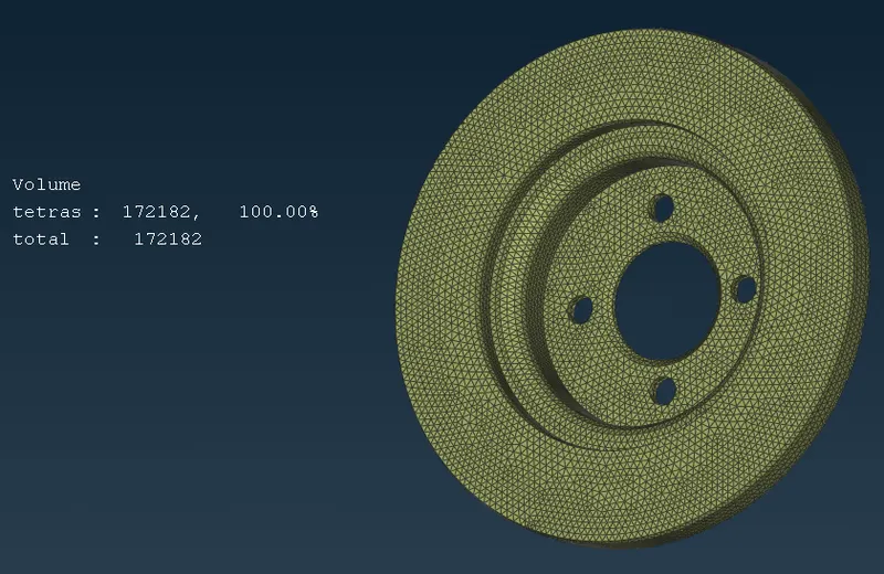
8. Volume Meshing done.
9. Cleared the elements whicha are falling for TET collapse.
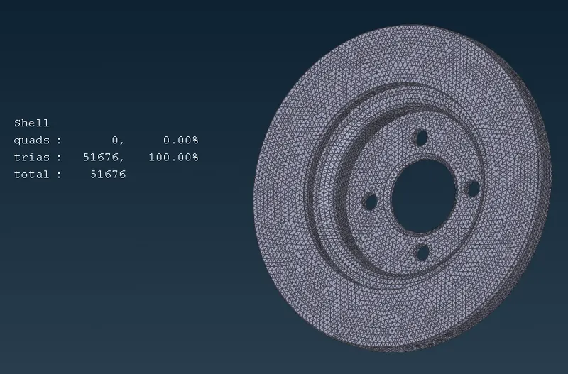
Surface meshing of rotor wheel disc
Volume meshing of rotor wheel disc
STEP 15 : PART 9 - SURFACE MESHING AND VOLUME MESHING OF TRAILING ARM
Same procedure followed by the Step 14for Non uniform thickness components.
Surface meshing of Trailing Arm
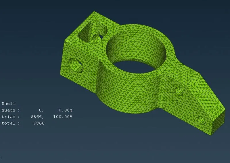
Volume meshing of Trailing Arm.
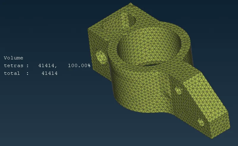
STEP 16 : PART 10 - SURFACE MESHING AND VOLUME MESHING OF TRAILING ARM BUSH
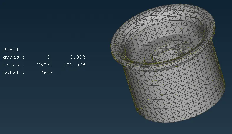
Surface meshing of Trailing Arm Bush
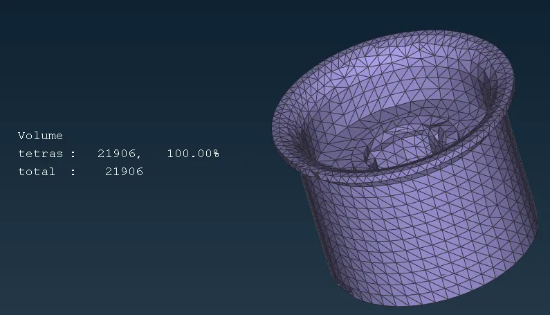
Volume meshing of Trailing Arm Bush
STEP 17 : PART 11 - SURFACE MESHING AND VOLUME MESHING OF TIE ROD
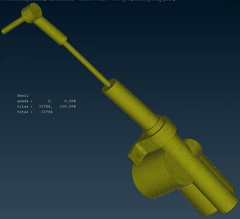
Surface meshing of Tie rod
Volume meshing of Tie rod
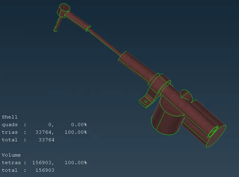
STEP 18 : PART 12 - SURFACE MESHING AND VOLUME MESHING OF SWAY BAR.
Surface meshing of sway bar
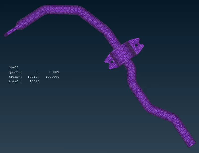
Volume meshing of sway bar
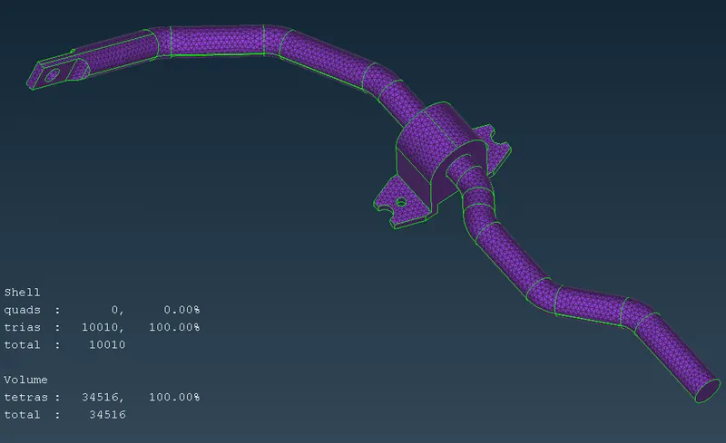
STEP 19 : PART 12 - SURFACE MESHING AND VOLUME MESHING OF CAR CHASSIS FRAME.
Surface meshing of car chassis frame
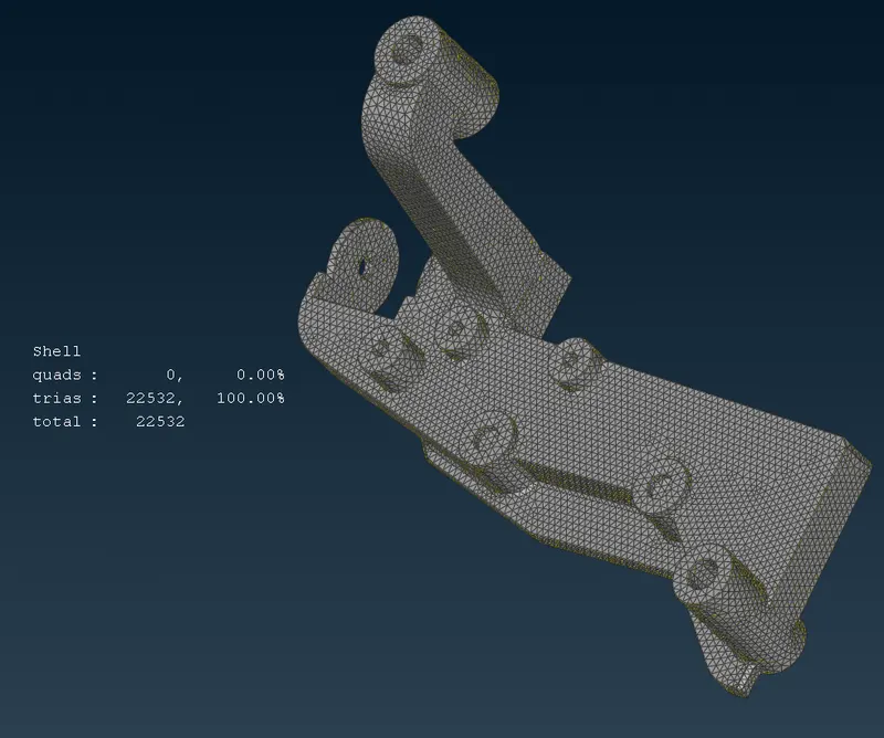
Volume meshing of car chassis frame
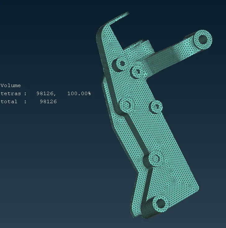
STEP 20 : PART 13 - SURFACE MESHING AND VOLUME MESHING OF BRAKE CALIPER.
Surface meshing of brake caliper
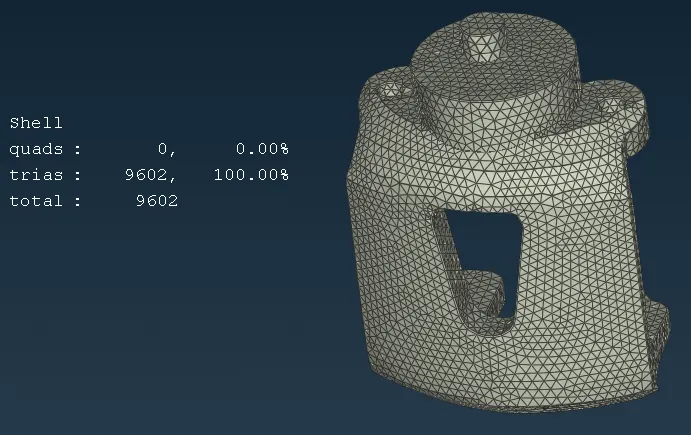
Volume meshing of brake caliper
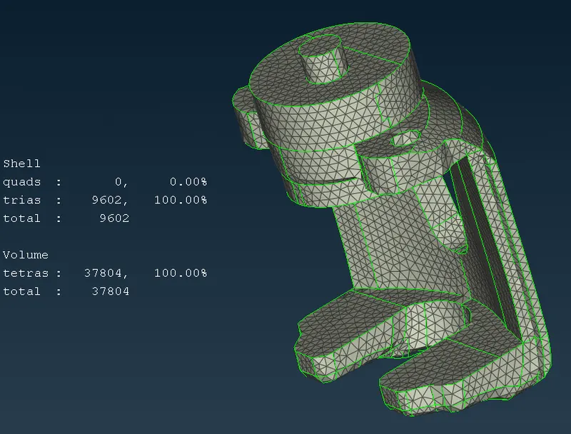
STEP 21 : PART 14 - SURFACE MESHING AND VOLUME MESHING OF BALL JOINT.
Surface meshing of Ball joint
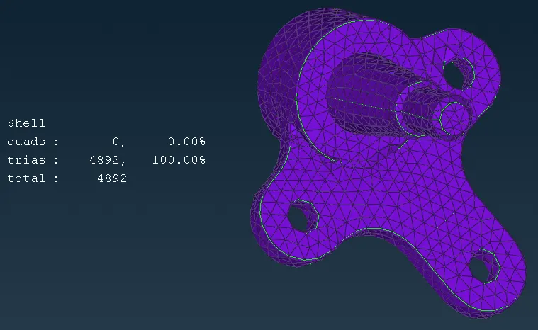
Volume meshing of Ball joint
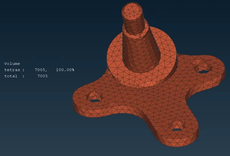
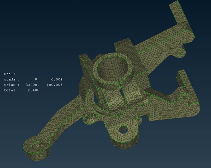
STEP 22 : PART 15 - SURFACE MESHING AND VOLUME MESHING OF KNUCKLE STEERING.
Surface meshing of Knuckle steeering
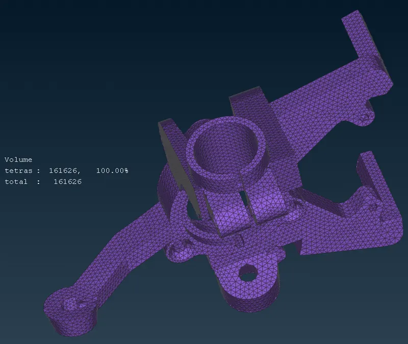
Volume meshing of Knuckle steeering
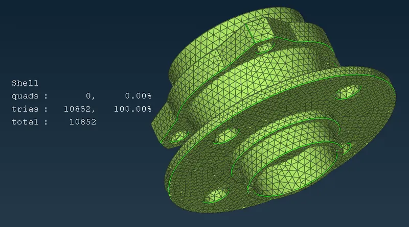
STEP 23 : PART 16 - SURFACE MESHING AND VOLUME MESHING OF WHEEL HUB.
Surface meshing of Wheel Hub
Volume meshing of Wheel Hub
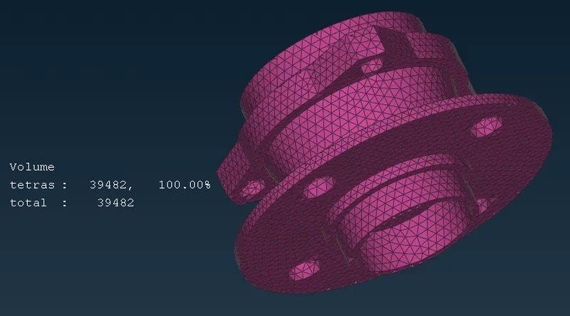
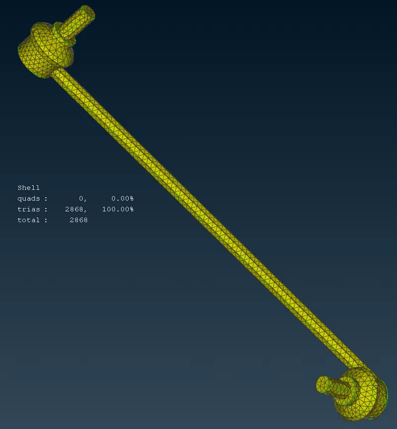
STEP 24 : PART 17 - SURFACE MESHING AND VOLUME MESHING OF PENDULUM BAR.
Surface meshing of pendulum bar
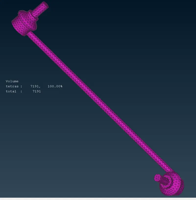
Volume meshing of pendulum bar
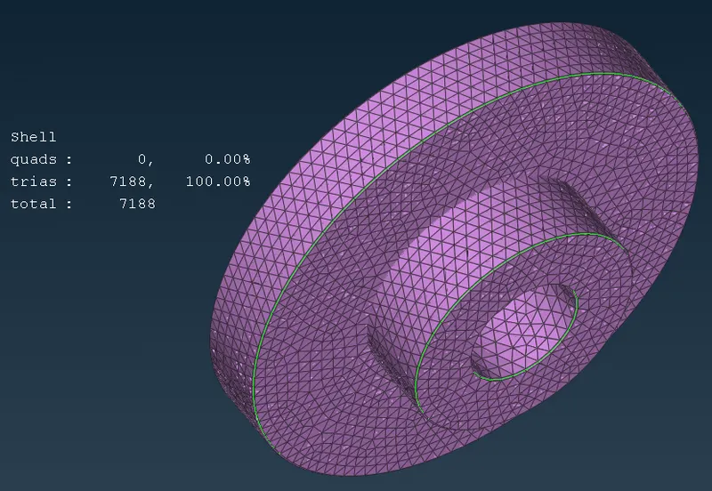
STEP 25 : PART 18 - SURFACE MESHING AND VOLUME MESHING OF TOP STRUCK.
Surface meshing of top struck
Volume meshing of top struck
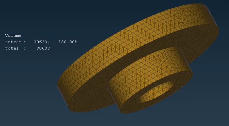
STEP 26 : PART 19 - SURFACE MESHING AND VOLUME MESHING OF BOTTOM STRUCK.
Surface meshing of Bottom struck
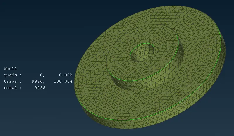
Volume meshing of Bottom struck
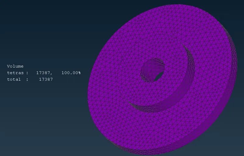
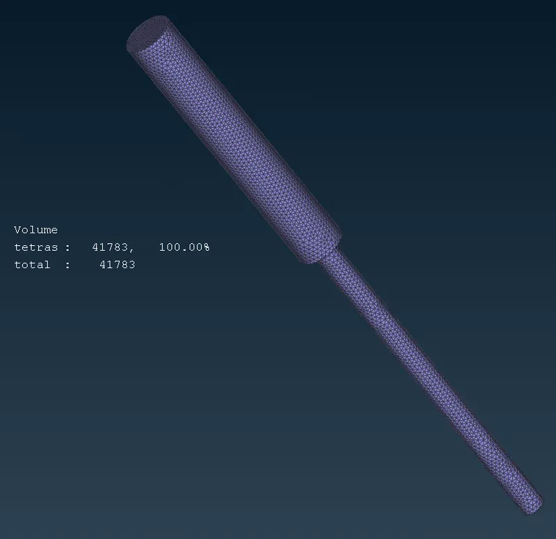
STEP 27 : PART 20 - SURFACE MESHING AND VOLUME MESHING OF SHOCK OBSERBER.
Surface meshing of Shock obserber
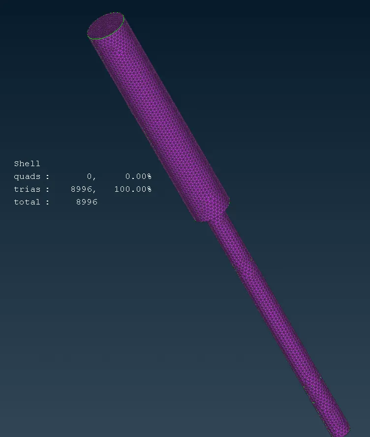
Volume meshing of Shock obserber
STEP 27 : PART 20 - REPRESENTATION OF COIL SPRING WITH 1D BAR ELEMENT.
1. Generated a middle curve for the spring. By using the middle option in the curves.
2. Connected the curve into a single curve . By using the connect(multi) option in curves.
3. Created a COG point for the curve to define the orientation.
4. Selected the CBAR element.
5. Changed the selection type to the curve box.
6. Selected the curve and give the middle mouse click.
7. Selected the orientation node.
8. Specify the element length. In this case, The Element length is taken as 3 mm.
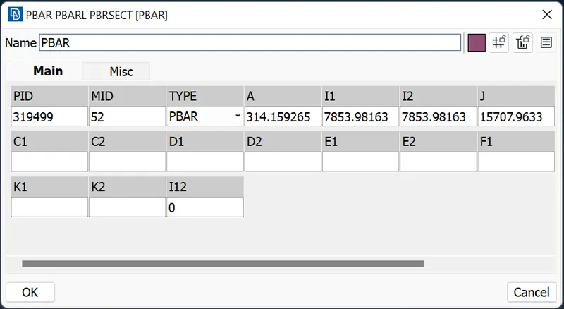
9. After Specifying the element length as 3 mm, Do middle mouse click and define a pid by creating a new PID.
10. Define Area by giving Radius of spring. i.e. Cross section radius of a spring as per the belown image,
11. Assigned the cross sectional radius of the spring element.It will calculate the cross sectional area and moment of inertia.
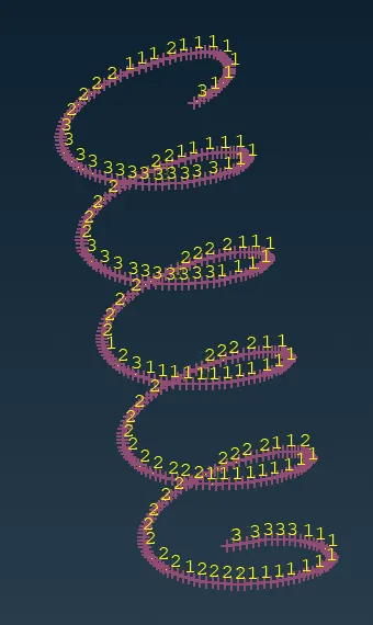
11. 1D bar elements will be created.
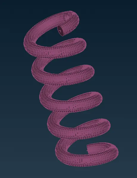
12. To see the representation of 1D bar elements as 3D (Solids), check the box of 1D detailed representation with
the solid in quality parameters .
13 . Click on apply and ok. The 1D bar element will be represented as a solid element.
STEP 28 : DEPLOYING CONNECTIONS IN THE REQUIRED COMPONENETS IN REAR SUSPENSION ASSEMBLY.
STEP 28 A : CLUSTER RBE2 CONNECTION IN BETWEEN RIM AND ROTATING WHEEL DISC.
1. The RBE2 Element represents the bolts and rivets.
2. Created Cluster RBE2 Elements,Go to Nastran Deck Module >> Elements >Many Nodes- sekected the nodes of an both parts
3.Then Click OK.
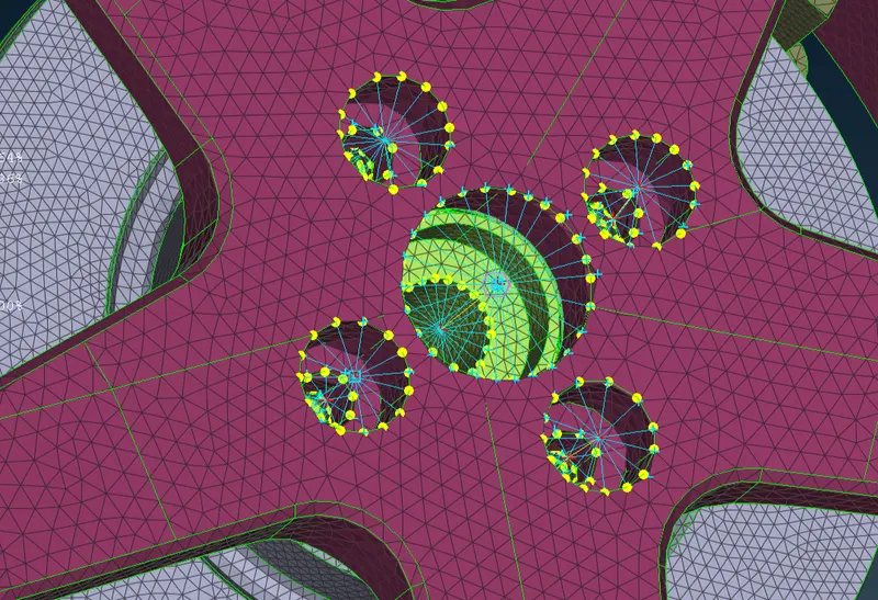
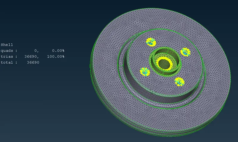
STEP 28 B : CLUSTER RBE2 CONNECTION IN BETWEEN WHEEL HUB AND ROTATING WHEEL DISC.
Same procedure followed as per the STEP28A
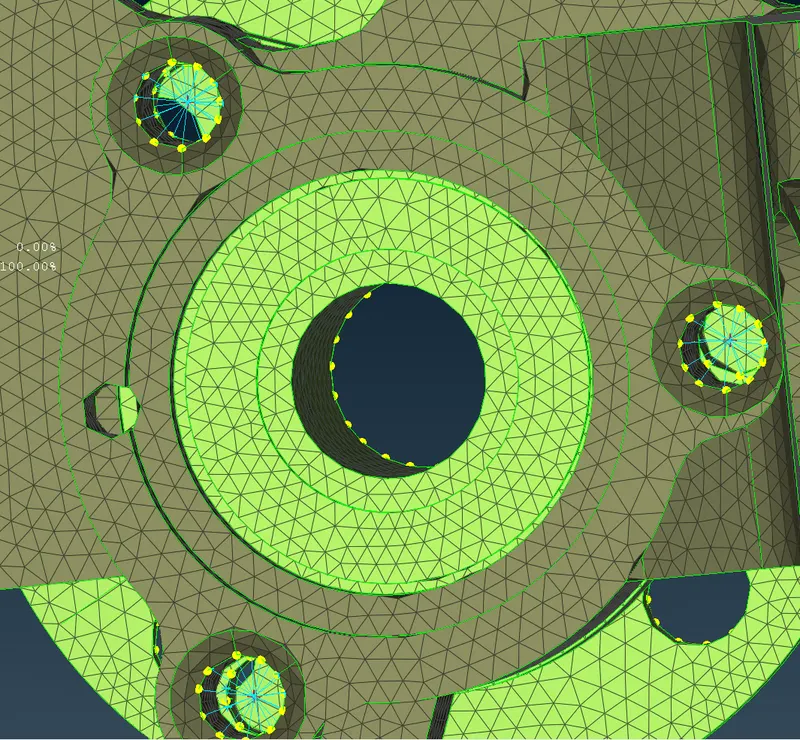
STEP 28 C : CLUSTER RBE2 CONNECTION IN BETWEEN WHEEL HUB AND KNUCKLE STEERING.
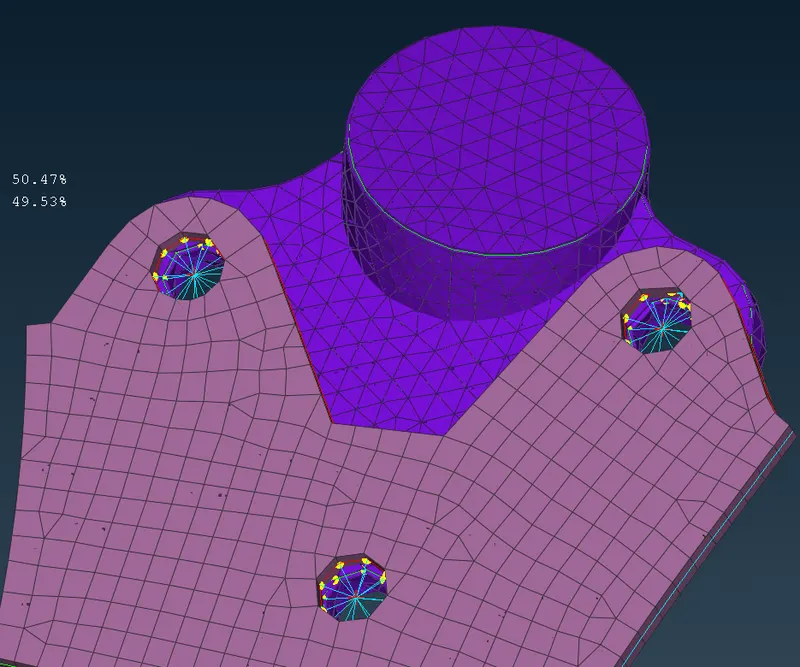
STEP 28 D : CLUSTER RBE2 CONNECTION IN BETWEEN CONTROL ARM WISHBONE AND BALL JOINT.
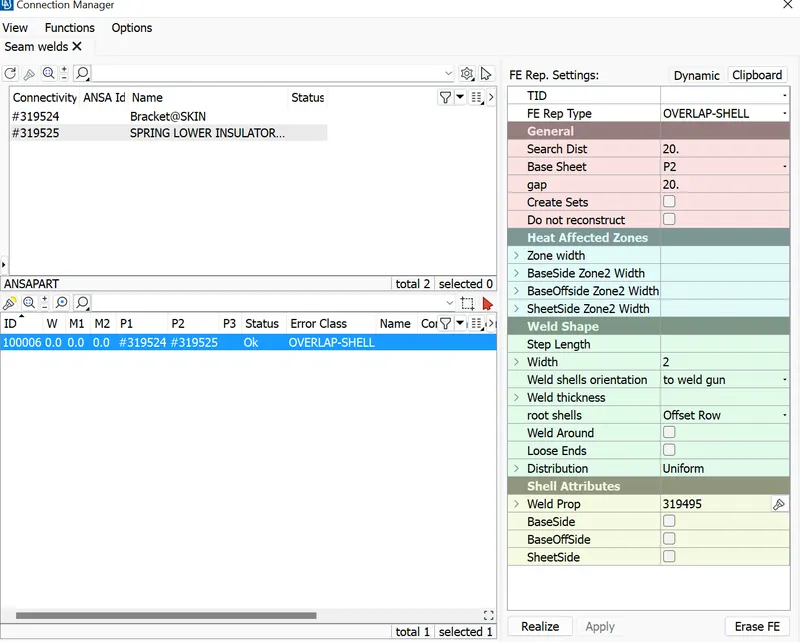
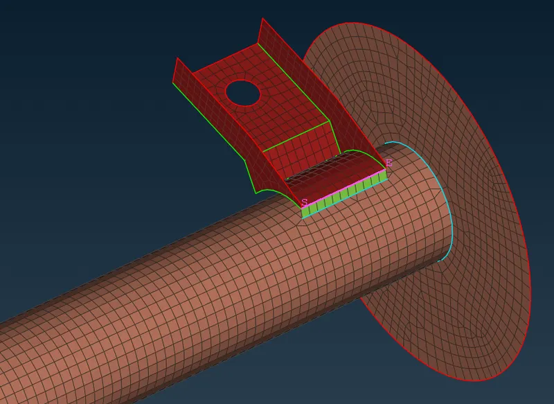
STEP 28 D : SEAM WELD CONNECTION IN BETWEEN SPRING LOWER INSULATOR AND BRACKET.
1. Creation of curve using MESH > PERIMETER > FEAT2CURVE .
2. To convert the curve into seam line by CONVERT option.
3. In connection manager selected the seam line and to select PIDs of Spring lower insulator and Bracket .
4. FE representation type as OVERLAP SHELL
5. Provide search distance value as 20 mm
6. Choosed the proper base sheet and provide width value is 2 mm .
7. Then creation of Weld PID of it , apply and realized it.
Seam weld joint connections in between Spring lower insulator and Bracket
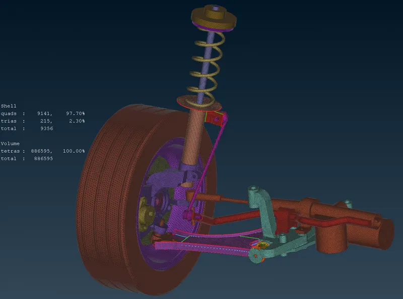
STEP 29 : TO PERFORM SYMMETRY OPERATION OF AN REAR SUSPENSION ASSEMBLY.
1. Reflect the entities to other side using transform tool.
2. To Reflect,Go to Utilities Panel > Transform >> Copy > selected the Half portion of the rear suspension assembly.
3. Selected symmetry option > mirror 3 points axis> selected the 3 nodes in the tie Rod.
4. Symmetry operation done.
Orthographic view Half portion of rear suspension assembly.
Orthographic view of overall of rear suspension assembly.
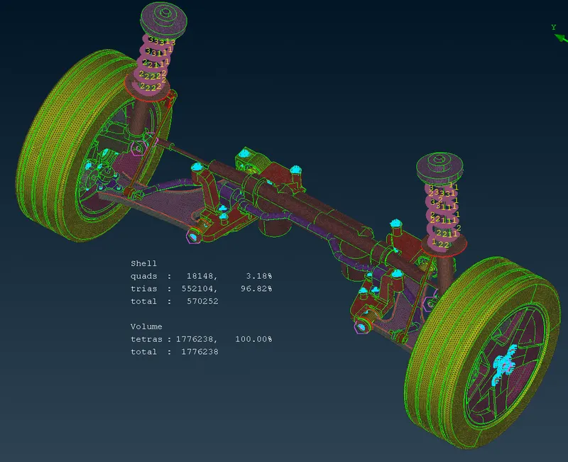
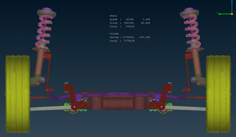
Front view of overall of rear suspension assembly.
RESULT:
1. Hence TetraMesh Generation Method-2D to 3D Conversion for Rear Suspension Assembly component with the following quality criteria has been done.
2.Hence there are no surface deformations in the geometry.
3.A well connectivity has been established between the surfaces.
4.The features have been captured properly.
5.A good mesh flow have been achieved.
6.Hence the Model has been reflected to the other side successfully.
7.Hence the connection has been deployed in required regions.
LEARNING OUTCOME :
In this Project 2 Rear Suspension Assembly Model Challenge,I came to know
1. How to 3D mesh a component properly without dent's,kink's and raised edges.
2.How to create a volume tetra mesh for the components.
3.How to generate a proper mesh flow without kinks,raised edges and dent's.
4.How to fix the elements failing for the tet collapse.