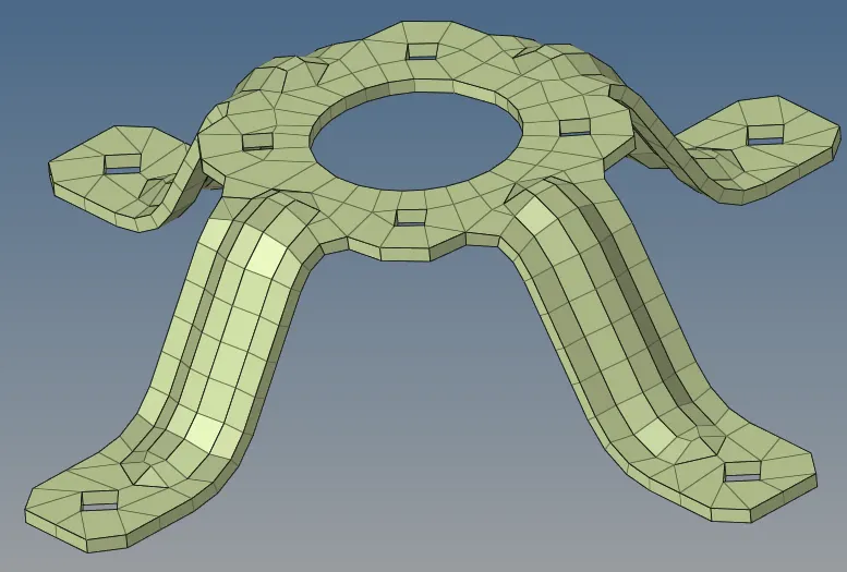
Assignment 1-2D Meshing Challenge
2D MESHING OF CLIP AND MOUNTING BRACKETS
AIM :
- To do geometrical cleanup of the mounting bracket models without any free edges.
- To extract the midsurface of the mounting bracket models.
- To do meshing of the mounting bracket models with mesh flow.
- To do assign the proper thickness,by creating a generic property.
GIVEN MODEL :
- hm file of practice model one .
- hm file of clip .
- hm file of mounting bracket model .
GIVEN DATA :
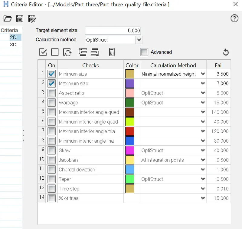
- Target length - 5 mm.
- Min length - 3.5 mm.
- Max length - 7 mm.
SOFTWARE USED :
Preprocessing software - Hyperwoks desktop 2022.
PROCEDURAL STEPS :
PART 1 : GEOMETRY CLEANUP OF THE PRACTICE MODEL WITHOUT ANY FREE EDGES.
STEP 1A : IMPORTED THE CAD GEOMETRY OF THE P[RACTICE MODEL.
- File > Import > geometry > file selection type -STEP > imported the practice model.
Imported the CAD model
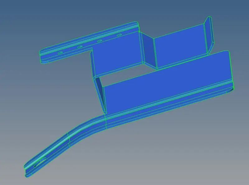
STEP 1B : PERFORMING TOPOLOGY REPAIR OF THE PRACTICE MODEL GEOMETRY .
- Putting the geometry in Topology mode using by Topo Option as shown.
Missed surfaces of the CAD model
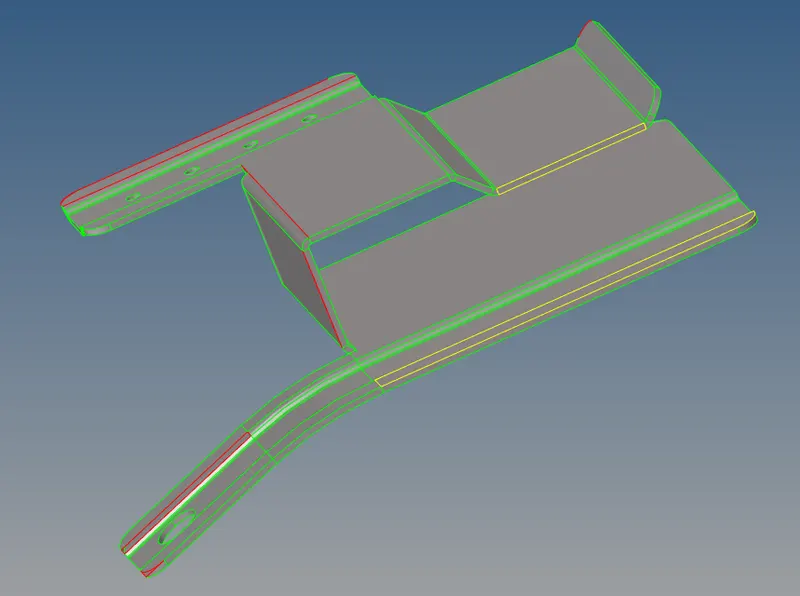
- Identify the Possible topology repairs. From the above, we can observe some surfaces are missing which can be fixed by filler Surface option.
- Main menu > geometry > quick edit > filler surface > selected the lines to fill the missing surfaces.
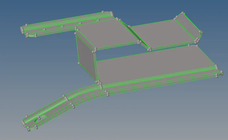
- Main menu > geometry > quick edit > toggle edge > selected the free edge lines between the surfaces > set the tolerance value > toggled it.
Geometric cleanup of the model after removal of free edges
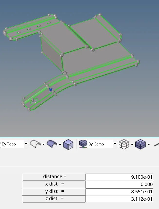
STEP 1B1 : THICKNESS MEASUREMENT ON THE PRACTICE MODEL GEOMETRY.
- Geometry > distance > 2 points > selected the 2 points > distance measured is 0.91 mm
STEP 1C : EXTRACTING MIDSURFACE OF THE PRACTICE MODEL GEOMETRY.
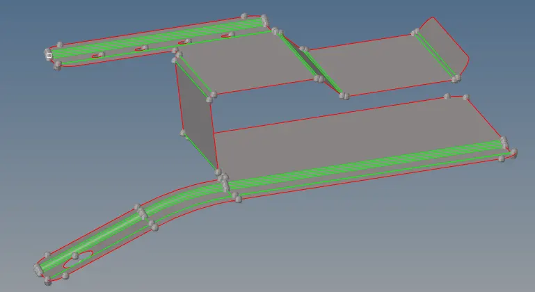
- To extract the midsurface by auto midsurface using options in skin offset method.
- Main menu > geometry >midsurface > automidsurface > Extract option- skin offset > selected the all surfaces > extracted it.
Midsurface of the practice model
STEP 1D: SET THE MESH PARAMETERS AND QUALITY CRITERA VALUES
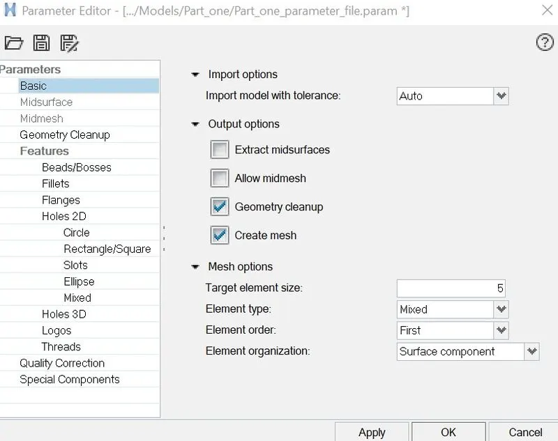
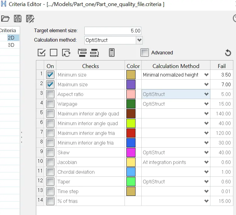
1. Before go to the meshing process, set the mesh parametes values and quality criteria values as per the given data.
2. Title bar > Preferences > parameter file settings > basic > changed the parameter values as per given data.
3. Title bar > Preferences > quality criteria file settings > changed the parameter values as per given data
STEP 1E: 2D MESHING OF THE PRACTICE MODEL .
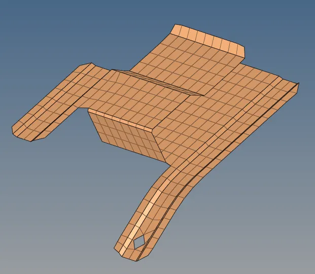
1. Performed meshing on the practice model by automesh method.
2. Mainmenu > 2D > automesh > set the target element size = 5mm > selected the surfaces > meshed it.
3. Achieving proper mesh flow was followed by the below steps.
(a) Reduced the trias concentration by Mainmenu > 2D > edit element > split > selected the elements > draw a spliiting line by points > splitted the elements.
Then Mainmenu > 2D > edit element > combine > selected 2 trias > combined into quads.
(b) (or) Mainmenu > 2D > split > click refine elements > selected the elements by path > splitted into elements.
Then Mainmenu > 2D > edit element > combine > selected 2 trias > combined into quads.
(c) Mainmenu > 2D > quality index > cleanup tools > Drag tria elements and combine tria elements > reduced the no of trias .
(d) Reduced the no of trias by Mainmenu > 2D > replace > node with other node > disabled the tria element.
(e) After spliitting the elements to perform smmoth operation to get uniform mesh flow by,
Mainmenu > 2D > smooth > plates > selected the elements > set the iterationvalues as 1 or 10 > smoothed it.
(f) (or) Mainmenu > 2D > quality index > cleanup tools > smooth > selected the elements > smoothed it.
(g) After splitting the elements alignment node will be changed , so nodes will aligned by
Mainmenu > geometry > node edit > aliogn node > selected the 1st and 2nd end node and selected nodes needs to be aligned.
(h) To get the proper alignment of node with midsurface construction line by ,
Mainmenu > tools > project > click to line option > selected the nodes wants to align and selected the construction line and
vector by nodes > alligned it.
(i) To improve the mesh flow by using rebuild mesh option,
Mainmenu > 2D > rebuild mesh > selected the elements > proper mesh flow got it.
STEP1F : CHECK THE EDGES OF PRACTICE MODEL.
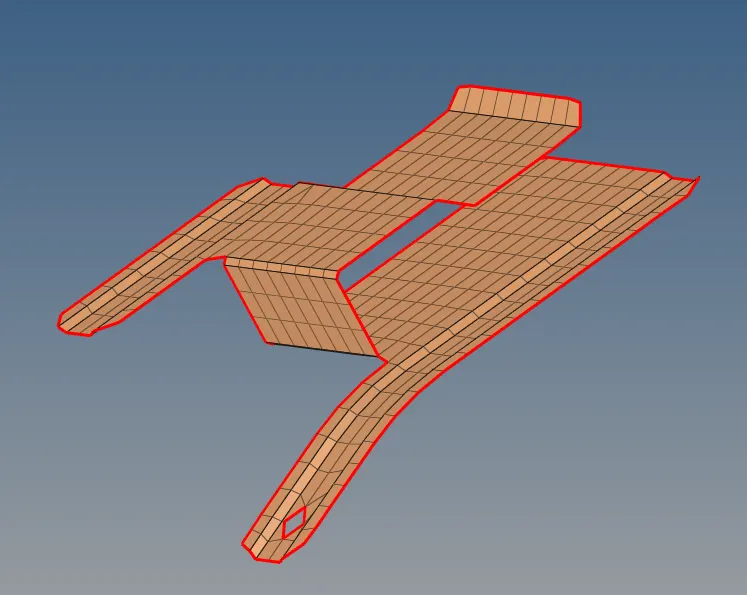
- After symmetry operation some of the edges was formed in between the elements Firstly check the edges are in the model by ,
- Mainmenu > tools > edges > selected the elements > set tolerance valueis 0.2 > run.
- Findout the unwanted edges in the elemets which are going to do preview equivalence and save equivalence it.
STEP1F : ASSIGNING THICKNESS OF THE PRACTICE MODEL.
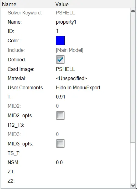
1. Then Created new property for outter hood, Set card image as a PSHELLassigning the thickness =0.91 mm.
2. Assigned property card to the mounting bracket model one midsurface component.
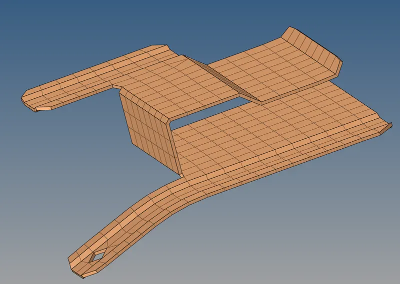
Final 3D FE representation of practice model
PART 2 : GEOMETRY CLEANUP OF THE CLIP MODEL WITHOUT ANY FREE EDGES.
STEP 2A : IMPORTED THE CAD GEOMETRY OF THE CLIP MODEL .
- File > Import > geometry > file selection type -STEP > imported the clip model.
Imported the CAD model
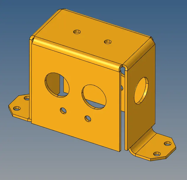
STEP 2B : PERFORMING TOPOLOGY REPAIR OF THE CLIP MODEL.
- Putting the geometry in Topology mode using by Topo Option as shown.
Missed surfaces of the CAD model
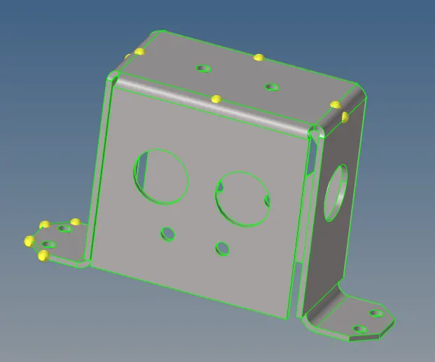
- Identify the Possible topology repairs. From the above, we can observe some surfaces are missing which can be fixed by filler Surface option.
- Main menu > geometry > quick edit > filler surface > selected the lines to fill the missing surfaces.
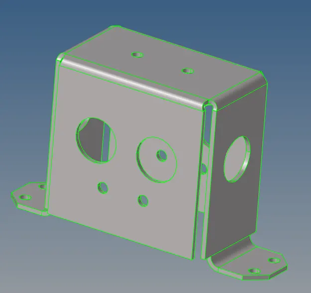
- Main menu > geometry > quick edit > toggle edge > selected the free edge lines between the surfaces > set the tolerance value > toggled it.
Geometric cleanup of the model after removal of free edges
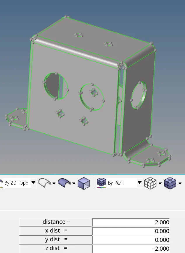
STEP 2B1 : THICKNESS MEASUREMENT ON THE CLIP MODEL.
- Geometry > distance > 2 points > selected the 2 points > distance measured is 0.91 mm.
STEP 2C : EXTRACTING MIDSURFACE OF THE CLIP MODEL.
- To extract the midsurface by auto midsurface using options in skin offset method.
- Main menu > geometry >midsurface > automidsurface > Extract option- skin offset > selected the all surfaces > extracted it.
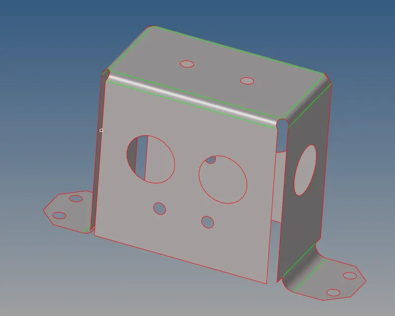
Midsurface of the clip model
STEP 2D: SET THE MESH PARAMETERS AND QUALITY CRITERA VALUES
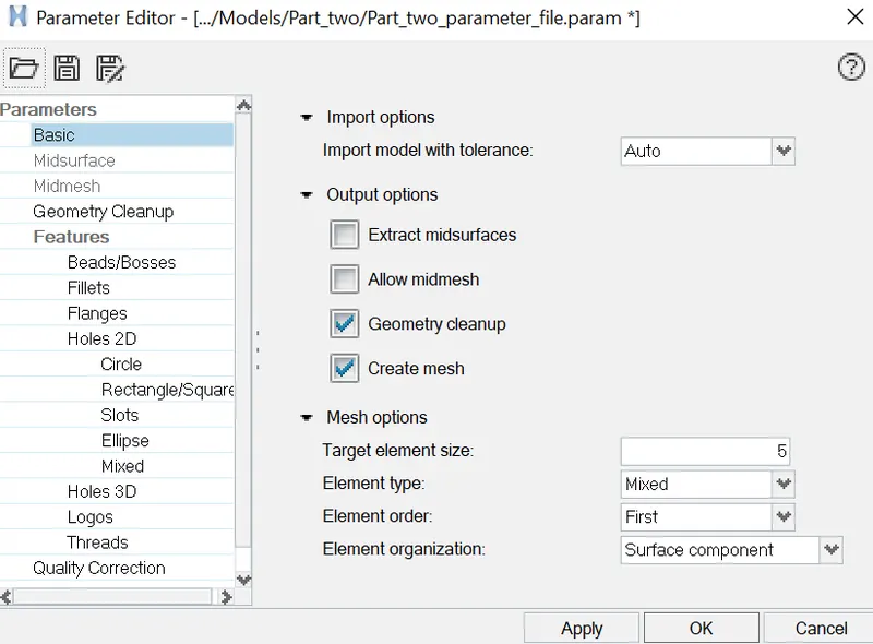
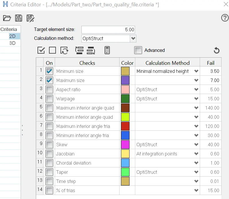
1. Before go to the meshing process, set the mesh parametes values and quality criteria values as per the given data.
2. Title bar > Preferences > parameter file settings > basic > changed the parameter values as per given data.
3. Title bar > Preferences > quality criteria file settings > changed the parameter values as per given data
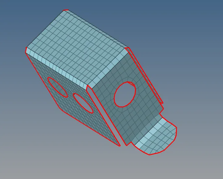
STEP 2E: 2D MESHING OF THE CLIP model .
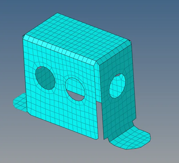
1. Performed meshing on the clip by automesh method.
2. Mainmenu > 2D > automesh > set the target element size = 5mm > selected the surfaces > meshed it.
3. Achieving proper mesh flow was followed by the below steps.
(a) Reduced the trias concentration by Mainmenu > 2D > edit element > split > selected the elements > draw a spliiting line by points > splitted the elements.
Then Mainmenu > 2D > edit element > combine > selected 2 trias > combined into quads.
(b) (or) Mainmenu > 2D > split > click refine elements > selected the elements by path > splitted into elements.
Then Mainmenu > 2D > edit element > combine > selected 2 trias > combined into quads.
(c) Mainmenu > 2D > quality index > cleanup tools > Drag tria elements and combine tria elements > reduced the no of trias .
(d) Reduced the no of trias by Mainmenu > 2D > replace > node with other node > disabled the tria element.
(e) After spliitting the elements to perform smmoth operation to get uniform mesh flow by,
Mainmenu > 2D > smooth > plates > selected the elements > set the iterationvalues as 1 or 10 > smoothed it.
(f) (or) Mainmenu > 2D > quality index > cleanup tools > smooth > selected the elements > smoothed it.
(g) After splitting the elements alignment node will be changed , so nodes will aligned by
Mainmenu > geometry > node edit > aliogn node > selected the 1st and 2nd end node and selected nodes needs to be aligned.
(h) To get the proper alignment of node with midsurface construction line by ,
Mainmenu > tools > project > click to line option > selected the nodes wants to align and selected the construction line and
vector by nodes > alligned it.
(i) To improve the mesh flow by using rebuild mesh option,
Mainmenu > 2D > rebuild mesh > selected the elements > proper mesh flow got it.
STEP2F : CHECK THE EDGES OF THE CLIP MODEL.
- After symmetry operation some of the edges was formed in between the elements Firstly check the edges are in the model by ,
- Mainmenu > tools > edges > selected the elements > set tolerance valueis 0.2 > run.
- Findout the unwanted edges in the elemets which are going to do preview equivalence and save equivalence it.
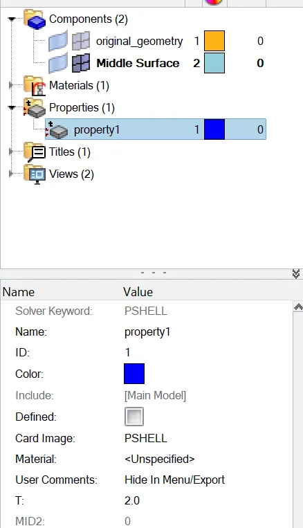
STEP2G : ASSIGNING THICKNESS OF THE CLIP MODEL.
1. Then Created new property for outter hood, Set card image as a PSHELL assigning the thickness =2 mm.
2. Assigned property card to the clip model midsurface component.
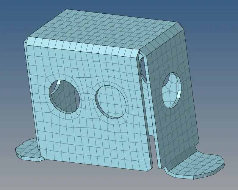
Final 3D FE representation of clip model
PART 3 : GEOMETRY CLEANUP OF THE MOUNTING BRACKET MODEL WITHOUT ANY FREE EDGES.
STEP 3A : IMPORTED THE CAD GEOMETRY OF THE MOUNTING BRACKET MODEL .
- File > Import > geometry > file selection type -STEP > imported the mounting bracket model.
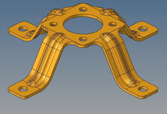
Imported the CAD model of mounting bracket model
STEP 3B : PERFORMING TOPOLOGY REPAIR OF THE MOUNTING BRACKET MODEL GEOMETRY .
- Putting the geometry in Topology mode using by Topo Option as shown.
Fixed Missed surfaces of the CAD model
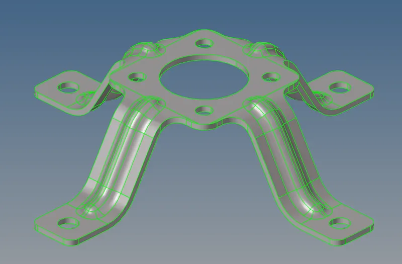
- Identify the Possible topology repairs. From the above, we can observe some surfaces are missing which can be fixed by filler Surface option.
- Main menu > geometry > quick edit > filler surface > selected the lines to fill the missing surfaces.
- Main menu > geometry > quick edit > toggle edge > selected the free edge lines between the surfaces > set the tolerance value > toggled it.
Geometric cleanup of the model after removal of free edges
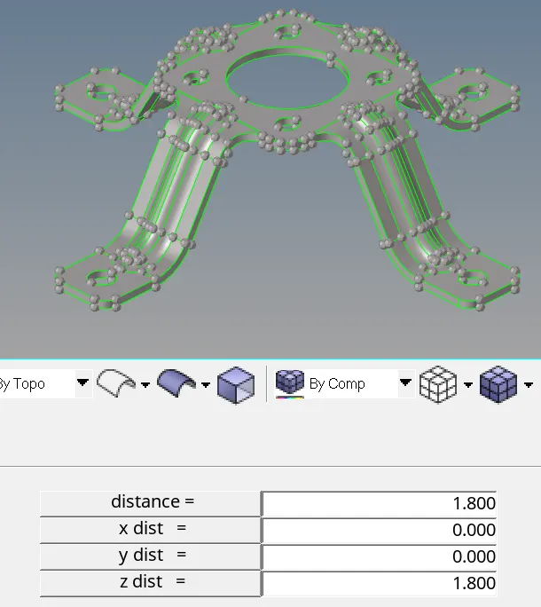
STEP 2B1 : THICKNESS MEASUREMENT ON THE MOUNTING BRACKET MODEL GEOMETRY.
- Geometry > distance > 2 points > selected the 2 points > distance measured is 1.8 mm.
STEP 3C : EXTRACTING MIDSURFACE OF THE MOUNTING BRACKET MODEL GEOMETRY.
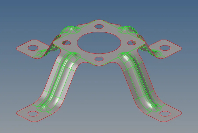
- To extract the midsurface by auto midsurface using options in skin offset method.
- Main menu > geometry >midsurface > automidsurface > Extract option- skin offset > selected the all surfaces > extracted it.
Midsurface of the mounting bracket model
STEP 3D: SET THE MESH PARAMETERS AND QUALITY CRITERA VALUES
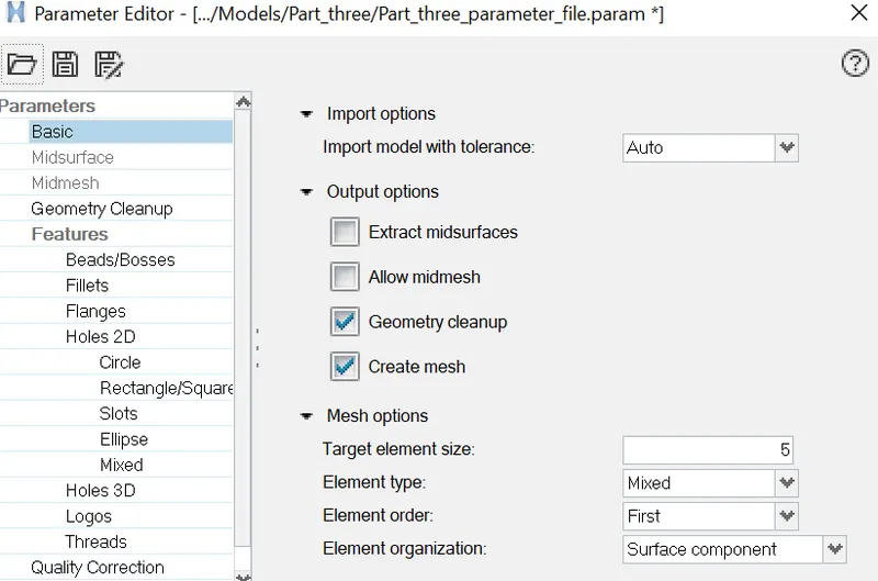
1. Before go to the meshing process, set the mesh parametes values and quality criteria values as per the given data.
2. Title bar > Preferences > parameter file settings > basic > changed the parameter values as per given data.
3. Title bar > Preferences > quality criteria file settings > changed the parameter values as per given data.
STEP 3E: MESHING OF THE MOUNTING BRACKET MODEL.
1. Performed meshing on the mounting bracket model by automesh method.
2. Mainmenu > 2D > automesh > set the target element size = 5mm > selected the surfaces > meshed it.
3. Achieving proper mesh flow was followed by the below steps.
(a) Reduced the trias concentration by Mainmenu > 2D > edit element > split > selected the elements > draw a spliiting line by points > splitted the elements.
Then Mainmenu > 2D > edit element > combine > selected 2 trias > combined into quads.
(b) (or) Mainmenu > 2D > split > click refine elements > selected the elements by path > splitted into elements.
Then Mainmenu > 2D > edit element > combine > selected 2 trias > combined into quads.
(c) Mainmenu > 2D > quality index > cleanup tools > Drag tria elements and combine tria elements > reduced the no of trias .
(d) Reduced the no of trias by Mainmenu > 2D > replace > node with other node > disabled the tria element.
(e) After spliitting the elements to perform smmoth operation to get uniform mesh flow by,
Mainmenu > 2D > smooth > plates > selected the elements > set the iterationvalues as 1 or 10 > smoothed it.
(f) (or) Mainmenu > 2D > quality index > cleanup tools > smooth > selected the elements > smoothed it.
(g) After splitting the elements alignment node will be changed , so nodes will aligned by
Mainmenu > geometry > node edit > aliogn node > selected the 1st and 2nd end node and selected nodes needs to be aligned.
(h) To get the proper alignment of node with midsurface construction line by ,
Mainmenu > tools > project > click to line option > selected the nodes wants to align and selected the construction line and
vector by nodes > alligned it.
(i) To improve the mesh flow by using rebuild mesh option,
Mainmenu > 2D > rebuild mesh > selected the elements > proper mesh flow got it.
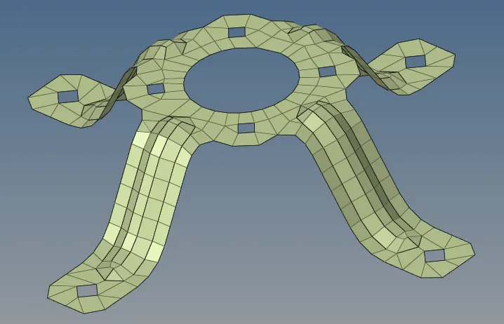
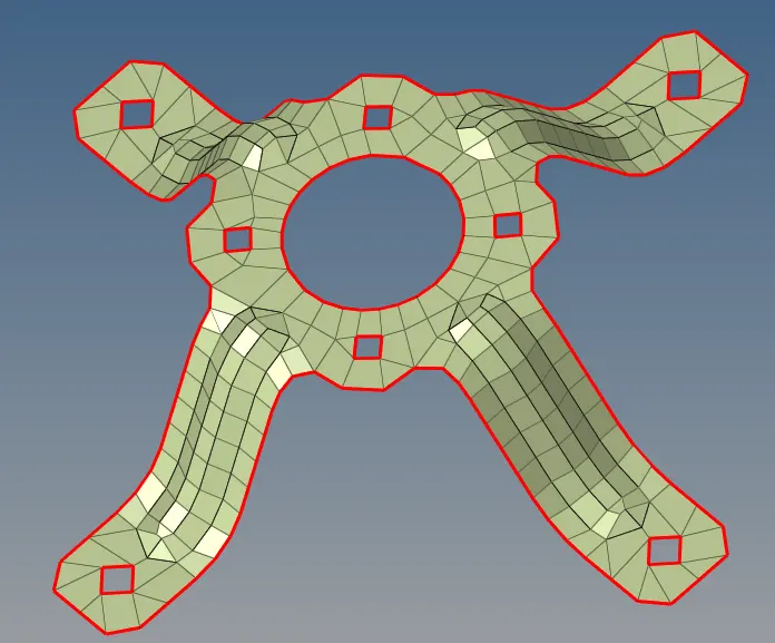
STEP3F : CHECK THE EDGES OF THE MOUNTING BRACKET MODEL .
- After symmetry operation some of the edges was formed in between the elements Firstly check the edges are in the model by ,
- Mainmenu > tools > edges > selected the elements > set tolerance valueis 0.2 > run.
- Findout the unwanted edges in the elemets which are going to do preview equivalence and save equivalence it.
STEP3G : ASSIGNING THICKNESS OF THE MOUNTING BRACKET MODEL.
1. Then Created new property for outter hood, Set card image as a PSHELL assigning the thickness =1.8 mm.
2. Assigned property card to the mounting bracket model two midsurface component.
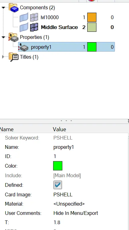
Final 3D FE representation of mounting bracket model