Bird Strike - Project - 2
BIRD STRIKE IN AERO ENGINE
AIM :
- To create the simulation of bird strike on the Aero Engine from the given FE model by using Ls-dyna.
REQUIREMENTS :
-
The blades should rotate at a constant velocity but the casing should remain stationary.
-
The cylindrical bird model should travel along its own axis and hit the blades.
-
Use elastic material for the bird(2000MPa) and the casing(200GPa).
-
The material model for the blades is attached.
-
The velocity of the engine blades and the birds can be chosen so that blade failure can be seen within a short span of time.
-
Follow a consistent numbering approach 100000+ for nodes, 500000+ for elements, and 1000+ for the parts.
-
All other keywords should be numbered within 10000-19999 while following a range for each one.
METHODOLOGY:
- The FE model consists of four parts that need to be separated and save partwise.
- The suitable cards is created and savedas .K file in a same folder
- The node number, element number, and part number are assigned as per given numbering approach and to conclude the final simulation create the main file with the *include the all .K files into the Main.K file and run the explicit simulation using mass scaling.
INTRODUCTION : BIRD STRIKE IN AERO ENGINE
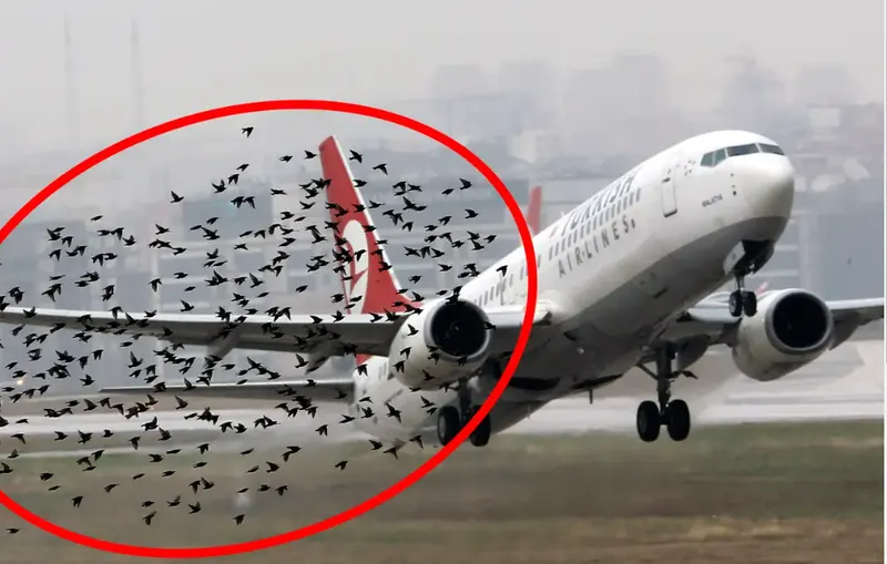
- According to Boeing's reports, three-quarters of bird strikes were related to aero-engines. Civil Aviation Authority (CAA) and International Civil Aviation Organization (ICAO)
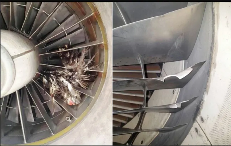
have similar conclusions. - Bird strikes can lead to permanent deformations, sudden decrease of thrust, even engine failure during the flight. Bird strikes on rotating blades can also cause slices of birds hitting other parts which may lead to greater damages.
- Bird strikes cannot be completely avoided. However, reduction of bird impacting on jet engines can be achieved by suitable design and manufacturing, through the mathematical modelling, simulation analysis and practical experiment of jet engines.
-
Bird strike Incidents increase by almost 50% in the first half of 2022According to the data from India's aviation regulator, the DGCA, bird strike incidents in the country have increased by 49.3% from January to July this year compared to the same period in 2021.
DELIVERABLES :
- The final submission must include the input file, animation, and a report.
- log their debugging process and include it in the report.
- The numbering approach should be described in the report.
- Usage of mass scaling is encouraged and the trial and error should be included in the report.
- The meshed file is provided which includes all the necessary components.
- Create a dummy model to create the scenario for quick debugging.
SOFTWARE USED :
- Solver tool - LS-Prepost 4.7.17 and LS-Run 1.0.100838.
PROCEDURAL STEPS :
STEP 1 : Import the k file
1. Imported the K format type of file using LS-Prepost software.
2. File > Import > LS-Dyna keyword file > browsed to selected the K type of file > imported it.
3. In order to check the keywords contained in the file we have to follow the below steps.
4. Side bar > model and part > keyword manager > checked the model.
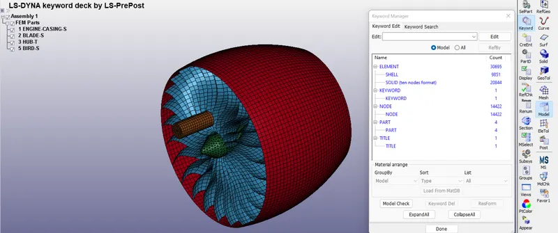
STEP 2 : Creation of material cards for all parts of aero engine and bird in a single K file
- Open the new .K file for material cards ,then to define a all material cards.
- Save as Material_cards.K file.
STEP 2A : Creation of material card for Engine casing
1. To create the material card for Engine casing by the following steps.
2. I had prefereed to choose material type is MAT_ELASTIC_001 as per given requirements.
3. This is Material Type 1. This is an isotropic hypoelastic material and is available for beam, shell, and solid elements in LS-DYNA.
4. Side bar > model and part > keyword manager > MAT > all > MAT_ELASTIC_001
5. Created new MID is 10001 (as per given numbering approach) and give title is Material_casing and specified the properties value as Kg-mm-ms unit system.
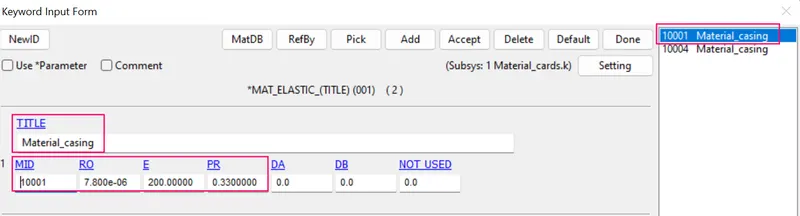
Where,
- RO -Density of steel = 7.85 *10⁻⁶ kg / mm³ .
- E - Youngs modulus = 200 Gpa =200 kg / mm ms²
- PR - Poissons ratio = 0.33
STEP 2B : To Transform engine blade K file into the newly material cards K file
- In order to transform given bladematerial AL4495. K file into the material_cards. K file by the following steps.
- Sidebar >model > keyword manager > all > include > transform > browsed to select bladematerial AL4495. K > accept and done.
- Side bar > model and part > keyword manager > checked the material datas of engine blade.
- Changed MID is 10002 (as per given numbering approach) and give title is Material_blade and specified the properties value as Kg-mm-ms unit system.
- Then deleted the include transform option in keyword manager, because we dont keep incluse transform content in Main file.
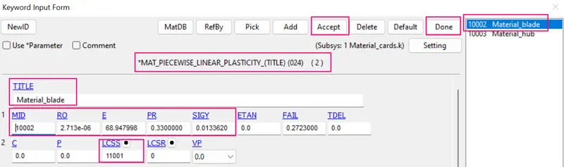
Where,
- RO -Density = 2.713 *10⁻⁶ kg / mm³ .
- E - Youngs modulus = 68.94 kg / mm ms²
- PR - Poissons ratio = 0.33
- SIGY - Yield stress = 0.0133 kg / mm ms².
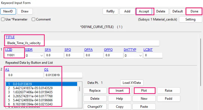
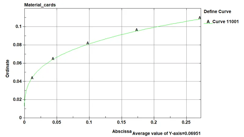
5. Checked the defined curve data in the material model file.
STEP 2C : Creation of material card for Engine hub
1. To create the material card for Engine hub by the following steps.
2. I had prefereed to choose material type is MAT_PIECEWISE_LINEAR_PLATICITY_024 as per given requirements.
3. This is Material Type 24, which is an elasto-plastic material with an arbitrary stress as a function of strain curve and arbitrary strain rate dependency can be defined.
4. Side bar > model and part > keyword manager > MAT > all > MAT_PIECEWISE_LINEAR_PLATICITY_024
5. Created new MID is 10003 (as per given numbering approach) and give title is Material_hub and specified the properties value as Kg-mm-ms unit system.
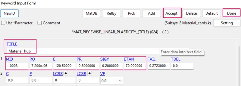
Where,
- RO -Density of cast iron = 7.25 *10⁻⁶ kg / mm³ .
- E - Youngs modulus = 120.5 Gpa =120.5 kg / mm ms²
- PR - Poissons ratio = 0.3
- SIGY - Yield stress = 200 Mpa= 0.2 kg / mm ms².
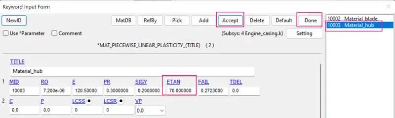
- ETAN- Tangent modulus = 70.
STEP 2D : Creation of material card for Bird
1. To create the material card for Bird by the following steps.
2. I had prefereed to choose material type is MAT_ELASTIC_001 as per given requirements.
3. This is Material Type 1. This is an isotropic hypoelastic material and is available for beam, shell, and solid elements in LS-DYNA.
4. Side bar > model and part > keyword manager > MAT > all > MAT_ELASTIC_001.
5. Created new MID is 10004 (as per given numbering approach) and give title is Material_Bird and specified the properties value as Kg-mm-ms unit system.
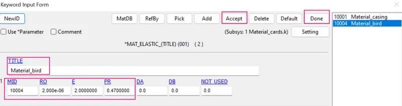
Where,
- RO -Density = 7.85 *10⁻⁶ kg / mm³ .
- E - Youngs modulus = 2 kg / mm ms²
- PR - Poissons ratio = 0.47
STEP 3 : Creation of scetion cards for all parts of aero engine and bird in a single K file
- Open the new .K file for section cards ,then to define a all section cards.
- Save as section_cards.K file.
STEP 3A : Creation of section card for Engine casing
1. In this section element formulation ,integration rule ,nodal thickness and cross sectional properties are defined.
2. 2. In order to create the section solid of engine casing by the following steps.
3. Side bar > model and part > keyword manager >all > section >SECID-12001(as per given numbering approach) > set ELFORM is 16(fully integrated shell element) > specified the thickness value is 3 mm > accept and done.
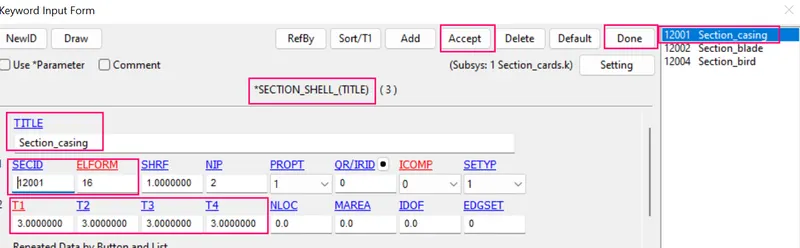
STEP 3B : Creation of section card for Engine blade
1. In this section element formulation ,integration rule ,nodal thickness and cross sectional properties are defined.
2. In order to create the section solid of engine blade by the following steps.
3. Side bar > model and part > keyword manager >all > section > SECID-12002 (as per given numbering approach) > set ELFORM is 16(fully integrated shell element) > specified the thickness value is 2 mm > accept and done.
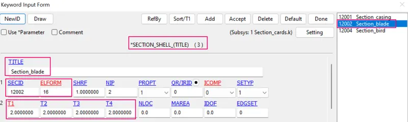
STEP 3C : Creation of section card for Engine hub
1. In this section element formulation is only defined.
2. In order to create the section solid of engine hub by the following steps.
3. Side bar > model and part > keyword manager >all > section >SECID-12003 (as per given numbering approach) > set ELFORM is 10 ( point tetrahedron element ) > accept and done.
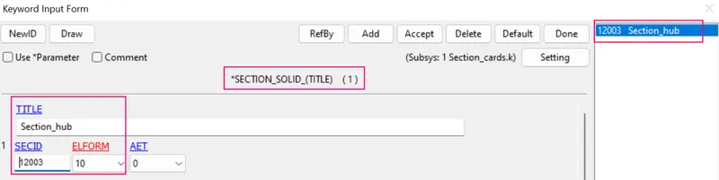
STEP 3D : Creation of section card for Bird
1. In this section element formulation ,integration rule ,nodal thickness and cross sectional properties are defined.
2. In order to create the section of bird by the following steps.
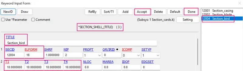
3. Side bar > model and part > keyword manager >all > section >SECID-12004 (as per given numbering approach) > set ELFORM is 16(fully integrated shell element) > specified the thickness value is 10 mm > accept and done.
STEP 4 : Creation of Part cards for all parts of aero engine and bird in a individual K file
- As per given aero engine with bird strike assembly FEM model , we have to separate the parts to save as a individual K file for each parts of an assembly.
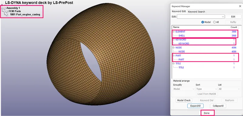
STEP 4 A : Creation of Part card for Engine casing FEM model in a individual K file.
- Import the K file of given assembly Aero engine with bird FEM model.
- Keep the engine casing FEM model and rest of the other FEM model should be deleted.
- Save as individual part of engine casing as a indivual K file.
- Checked the keywords of Engine casing FEM model.
- Created new PID is 1001 (as per given numbering approach) and give title is Part_casing .
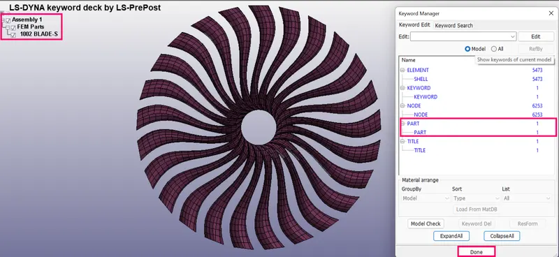
STEP 4B : Creation of Part card for Engine blades FEM model in a individual K file.
- Import the K file of given assembly Aero engine with bird FEM model.
- Keep the engine blade FEM model and rest of the other FEM model should be deleted.
- Save as individual part of engine blades as a indivual K file.
- Checked the keywords of Engine blades FEM model.
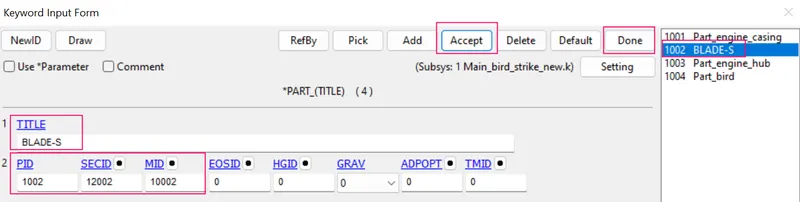
- Created new PID is 1002 (as per given numbering approach) and give title is Part_blade .
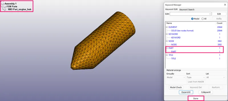
STEP 4C : Creation of Part card for Engine hub FEM model in a individual K file.
- Import the K file of given assembly Aero engine with bird FEM model.
- Keep the engine hub FEM model and rest of the other FEM model should be deleted.
- Save as individual part of engine hub as a indivual K file.
- Checked the keywords of Engine hub FEM model.
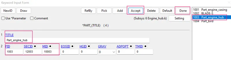
- Created new PID is 1003 (as per given numbering approach) and give title is Part_hub .
STEP 4D : Creation of Part card for bird FEM model in a individual K file.
- Import the K file of given assembly Aero engine with bird FEM model.
- Keep the bird FEM model and rest of the other FEM model should be deleted.
- Save as individual part of bird as a indivual K file.
- Checked the keywords of bird FEM model.
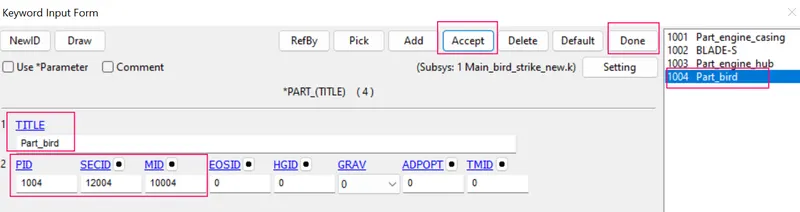
- Created new PID is 1004 (as per given numbering approach) and give title is Part_bird .
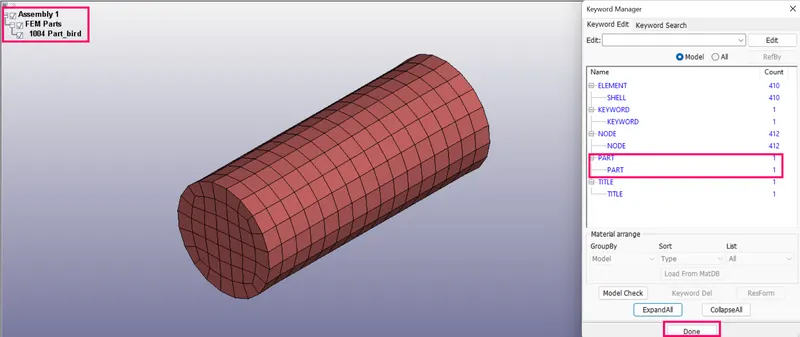
STEP 5 : Creation of contact cards.
- Open the new .K file for contact cards ,then to define a all contact cards.
- Save as contact_cards.K file.
STEP 5A : Creation of contact card of surface of engine hub to surface of engine blade.
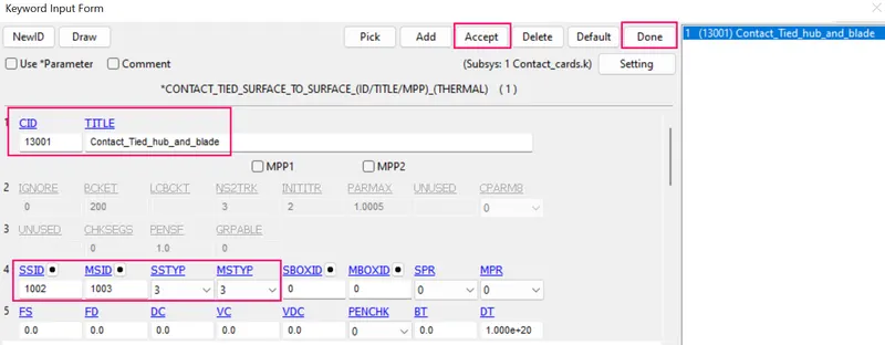
- Hence the blades should rotate according to the hub, *CONTACT_TIED_SURFACE_TO_SURFACE is used to tied the surfaces with the blade as a slave and hub as master.
- In order to create the contact card by the following steps.
- Side bar > model and part > keyword manager > all > contact > TIED_SURFACE_TO_SURFACE > CID-13001 (as per given numbering approach) > Title is Contact_tied_hub_and_blade > choosed SSTYP is 3 and MSTYP is 3 for Part ids > SSID is slave blade part id is 1002 and MSID is master hub part id is 1003 > accept and done.
- Saved this file as Contact_cards.k.
STEP 5B : Creation of contact card of surface of blade to surface of bird.
- In contact_cards.K file to create another contact card of surface of blade to surface of bird.
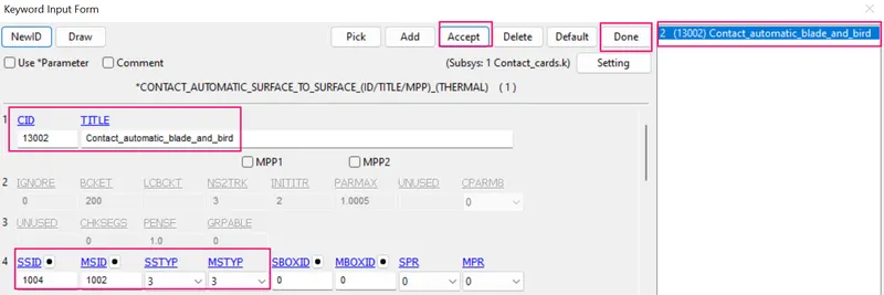
- In order for the bird needs to hit the blade *CONTACT_AUTOMATIC_SURFACE_TO_SURFACE is used as the bird as a slave and blade as a master.
- In order to create the contact card by the following steps.
- Side bar > model and part > keyword manager > all > contact > CONTACT_AUTOMATIC_SURFACE_TO_SURFACE > CID-13002 (as per given numbering approach) > Title is Contact_automatic_blade_and_bird > choosed SSTYP is 3 and MSTYP is 3 for Part ids > SSID is slave bird part id is 1004 and MSID is master blade part id is 1002 > accept and done.
STEP 5C : Creation of contact card of surface of casing to surface of blades.
- In contact_cards.K file to create another contact card of surface of casing to surface of blades.
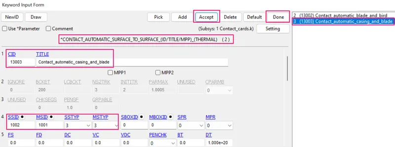
- The blade should not suppose to penetrate the casing. Again *CONTACT_AUTOMATIC_SURFACE_TO_SURFACE is used as the blade to be slave and casing as a master
- In order to create the contact card by the following steps.
- Side bar > model and part > keyword manager > all > contact > CONTACT_AUTOMATIC_SURFACE_TO_SURFACE > CID-13003 (as per given numbering approach) > Title is Contact_automatic_casing_and_blade > choosed SSTYP is 3 and MSTYP is 3 for Part ids > SSID is slave blade part id is 1002 and MSID is master casing part id is 1001 > accept and done.
STEP 5D : Creation of single surface contact for blades.
- In contact_cards.K file to create another contact card of single surface of blades.
- Eventually, once the bird hits the blades the deformed blades not supposed to penetrate with each other,So *CONTACT_AUTOMATIC_SINGLE_SURFACE is used as the blades is slave
- In order to create the contact card by the following steps.
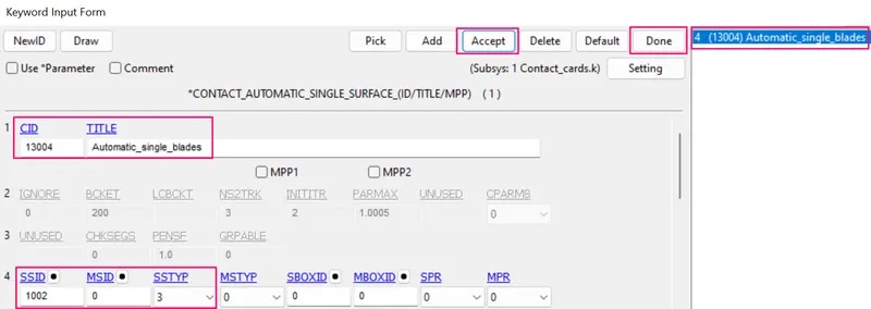
- Side bar > model and part > keyword manager > all > contact > CONTACT_AUTOMATIC_SINGLE_SURFACE > CID-13004 (as per given numbering approach) > Title is Contact_automatic_single_blades > choosed SSTYP is 3 for Part id > SSID is slave blade part id is 1002 > accept and done.
STEP 6 : Define boundary condition and velocity generation.
- Open the new .K file for boundary and velocity cards ,Then to define a SPC and velocity generation cards.
- Save as a Boundary_velocity.K file.
STEP 6A : Creation nodeset to the Engine casing.
- Before creation on boundary condition on casing we have to create the Nodeset id for casing.
- Inorder to create the Nodeset id for casing by the following steps.
- First of all open the Engine_casing.k file in Ls-prepost.
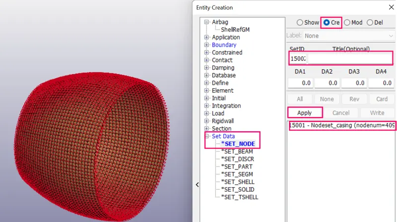
- Side bar > model > create entity >Set data >SET_NODE > NSID-15001 (as per numbering approach) > Title is Nodeset)casing > select the nodes in casing by picking part option > apply and done.
- Save the Engine_casing.k file and closed it.
STEP 6B: Creation of boundary condition on Casing.
- Open the Boundary_velocity.K file.
- Though the turbine engine case supposed to be fixed at the airplane wing.
- It has to be constrained in all the directions i.e, Translation and Rotation Initial Velocity.
- In order to create the boundary condition by the following steps.
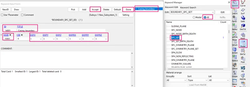
- Sidebar > Model > keyword manager > all > Boundary > SPC_SET > new Id-14001 (as per given numbering approach) > Title is casing_boundary > give NSID is 15001(as per given numbering approach) > constrained in all directions > accept and done.
STEP 6C : Define the initial velocity to the bird.
- The average velocity of the bird travels from the references is observed to be approximately 20 to 80 mm/ms.
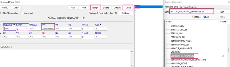
- Here the Average velocity of the bird is assigned to be VX=50 mm/ms along the X-axis translative direction.
- In order to define the initial velocity generation to the bird by the following steps.
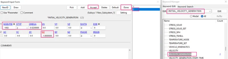
- Sidebar > Model > keywordmanager > all > Initial > Velocity generation > PID-1004 (as per given numbering approach) > STYP is 2 For PIDs > Vx=50 mm/ms > accept and done.
STEP 6D : Define the angular velocity to the engine blades.
- The angular velocity of the blades is roughly around an average speed of around 3000 to 20000 rpm Considering 5000 rpm and convert it to radiant.
- From which angular velocity OMEGA=0.523 rad/ms, NX=1 (x-direction cosine)
- In order to define the initial velocity generation to the bird by the following steps.
- Sidebar > Model > keywordmanager > all > Initial > Velocity generation > PID-1002 > STYP is 2 For PIDs > OMEGA=0.523 rad/ms > Nx=1 (direction cosine)> accept and done.
STEP 7 : Define the control cards.
- Open the new .K file for control cards ,then to define a all control cards.
- Save as a Control_cards.K file.
STEP 7A : Define a CONTROL_TERMINATION card.
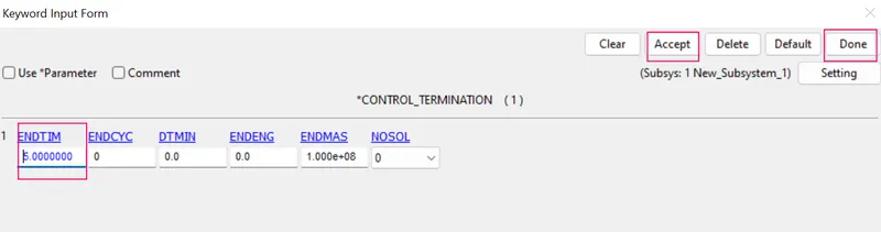
- The main purpose of control termination card is to stop the job.
- In order to define the control termination card by the following steps.
- Side bar > model and part > keyword manager > control > termination > specify termination time is 3 ms > accept and done.
STEP 7B : Define a CONTROL_ENERGY card.
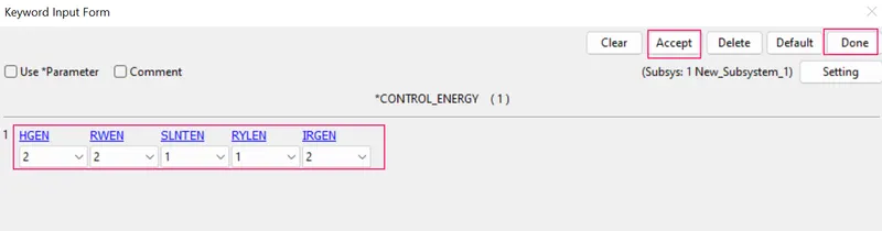
- Purpose of control energy card to Provide controls for energy dissipation options.
- In order to define the control energy card by the following steps.
- Side bar > model and part > keyword manager > control > Energy > HGEN=2 (hourglass energy is computed and included in the energy balance)> RWEN=2 (energy dissipation is computed and included in the energy balance ) > IRGEN=2 (initial reference geometry energy is computed and included in the energy balance as part of the internal energy ) > accept and done.
STEP 7C : Define a CONTROL_TIMESTEP card.
STEP 7C1 : Define a time step curve.
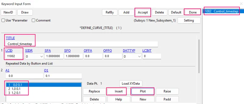
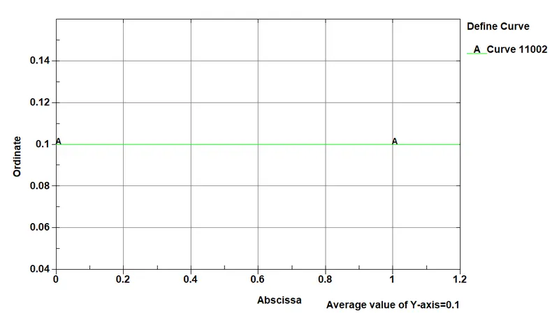
- Before define the control timestep card , we have to define the curve for controlling timestep.
- In order to define the curve for controlling timestep by the following steps.
- Side bar > model and part > keyword manager > all > define > curve > LCID-11002 (as per given numbering approach) > specify X,Y time step data > insert > plot > accept and done.
STEP 7C2 : Define a CONTROL_TIMESTEP card
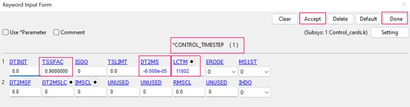
- Purpose of control timestep card is to set structural time step size control using different options.
- In order to define the controlling timestep card by the following steps.
- Side bar > model and part > keyword manager > all > control > timestep > TSSFAC=0.9 > DT2MS=-6.0*e-05 > assigned LCTM is 11002 > plot > accept and done.
STEP 8 : Define the Database cards.
- Open the new .K file for database cards ,then to define a Binary plot ,ASCII and Extend binary cards.
- Save as a Database_cards.K file.
STEP 8A :To define the output database as Binary D3 plot.
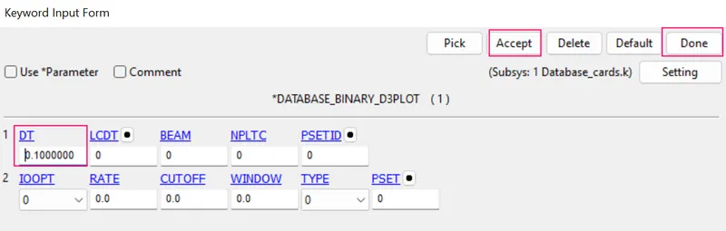
- DATABASE_BINARY_D3PLOT ensures d3 plot files which its stores stress strain contour of the entire deformed model.
- In order to create the DATABASE_BINARY_D3PLOT by the fllowing steps.
- Side bar > model and part > keyword manager > database > select DATABASE_BINARY_D3PLOT > DT value is 0.1 ms is a time interval between output states > accept & done.
STEP 8B :To define the output database as ASCII.
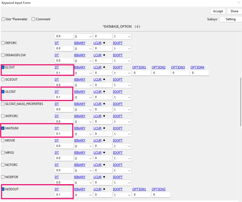
- ASCII can generate different outputs such as force generated in a contact like total energy and material energy etc.
- In order to create the ASCII by the fllowing steps.
- Side bar > model and part > keyword manager > database > select ASCII_option > checked GLSTAT ,MATSUM,ELOUT and NODOUT >specify all DT value is 0.1ms > accept & done.
STEP 8C :To define the output database as extend Binary.
- Now we have everything for the simulation but to extract the results we need to create a database cards for the model.
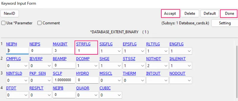
- We also need to generate the strain outputs. To do that, we can create a keyword by going to Keyword manager and selecting DATABASE > EXTENT_BINARY.
- To create the database extend binary card by the following steps,
- Side bar > model > keyword manager > all > DATABASE > EXTEND_BINARY> and give STRFLG as ‘1’, this is due to extract the true strain values for the model and accept the card.
STEP 9 : Creation of main .K file and Include the all above cards.K files to the Main_bird_strike_new.K file
- To create the new Main.K file in ls-prepost to included the above created .K files of section cards, material cards ,part cards,contact cards,control cards, Boundary & velocity cards , energy cards,database cards
- In order to create the include the .K files by the following steps.
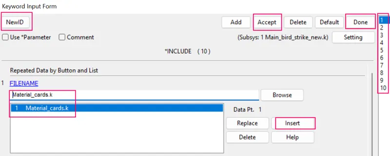
- Sidebar > Model > keywordmanager > all > include > Browsed to selected the .K files of material_cards.K, section_cards.K, Engine_casing.K, Engine_blade.K, Engine_hub.K and bird.K,contact_cards.K,control_cards.K, Boundary_velocity,K , energy_cards,K,Database_cards.K >Click new ID for each and every individual file before browsed to selecte the . k file > insert > accept and done.
- Save file names as Main_bird_strike_new.K file.
- Performed included the all .K files into the Main_bird_strike_new.K file.
- Closed the Main_bird_strike_new.K file.
STEP 10 : Checked the all keywords in Main_bird_strike_new.K file.
- Then import the Main_bird_strike_new.K file.
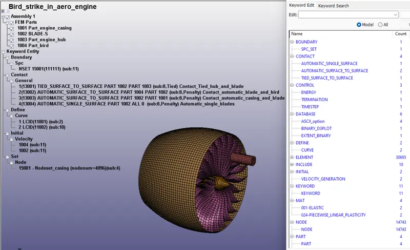
- Checked the all included cards are avaliable in keyword manager in Main_bird_strike_new.K file.
- Checked the assigned MIDs and SECIDs to the relevant PIDs.
- Checked the NSIDs and PIDS assigned relevant cards.
STEP 11 : Check the material cards and section cards to their relative part cards.
- In order to check the material cards and section cards to their relative part cards in Main_bird_strike_new.K fileby the foolwing steps.
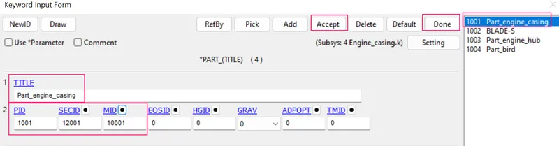
- Side bar > model and part > keyword manager >model > part > checked assigned the MID and SECID cards to their relative parts >accept and done.
STEP 11A : Check the engine casing material card and engine casing section card to engine casing part card.
- Side bar > model and part > keyword manager >model > part > Checked assigned the MID and SECID cards to engine casing part card >accept and done.
STEP 11B : Check the engine blade material card and engine blade section card to engine blade part card.
- Side bar > model and part > keyword manager >model > part > checked assigned the MID and SECID cards to engine blade part card >accept and done.
STEP 11C : Check the engine hub material card and engine hub section card to engine hub part card.
- Side bar > model and part > keyword manager >model > part > checked assigned the MID and SECID cards to engine hub part card >accept and done.
STEP 11D : Check the bird material card and bird section card to bird part card.
- Side bar > model and part > keyword manager >model > part > checked assigned the MID and SECID cards to bird part card >accept and done.
- Similarly checked the other keywords ids are properly assigned automatically.
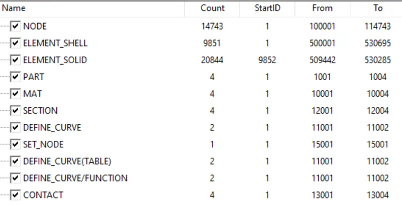
STEP 12 : Numbering approach of all keywords used in Bird strike in aero engine project.
STEP 12A : Numbering approach of each keywords as per given requirements.
- Numbering approach 100000+ for nodes, 500000+ for elements, and 1000+ for the parts.
- All other keywords should be numbered within 10000-19999
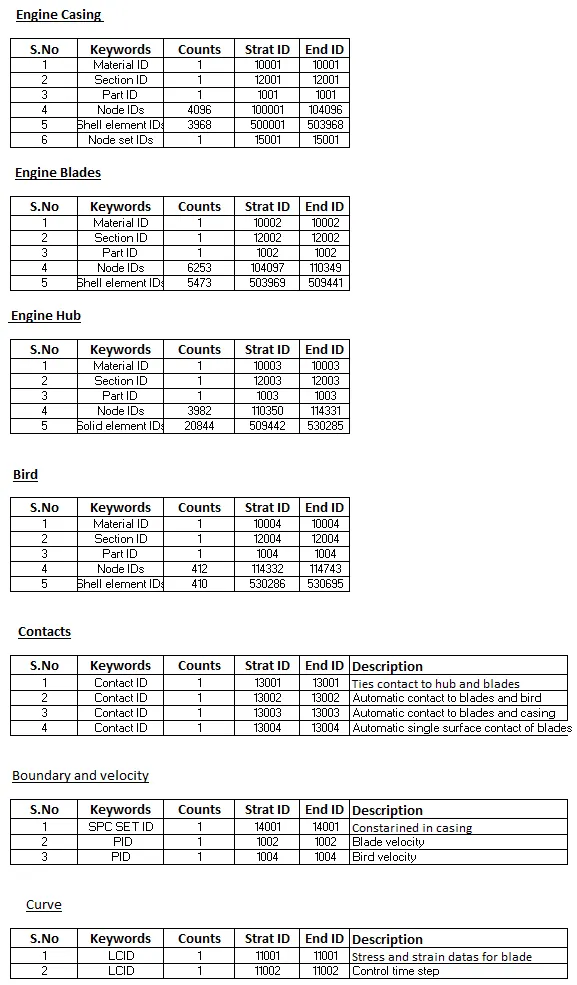
STEP 12B : Numbering approach of all keywords in Main_bird_strike_new.K file
STEP13 : Model checkup
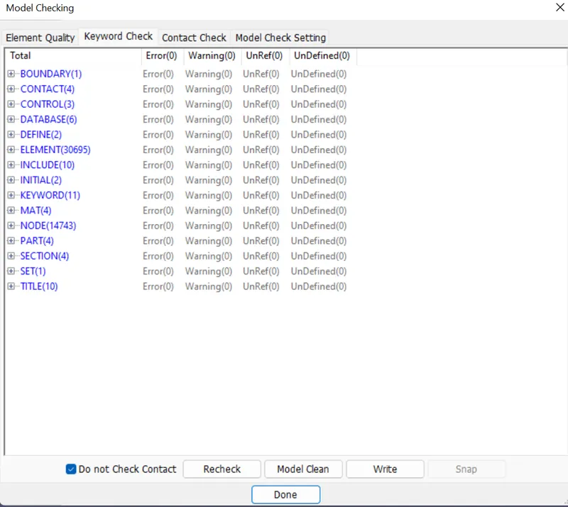
- The model is checked for any errors before solving using model checker.
- After all the errors are cleared, the drop test setup is saved and is ready to run in LS DYNA manager for solving the scenario.
- Warnings we can ignore ,once model check is run , it will look like as shown in picture below.
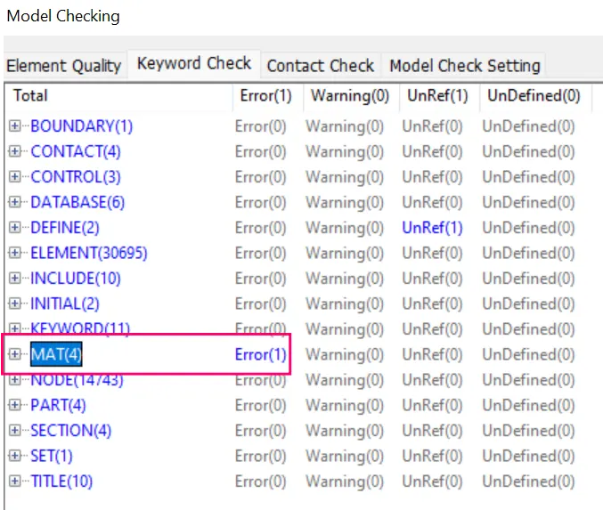
STEP13A : Debugging the errors
- Error is in Engine hub material card didnot define the strain hardening behaviour.
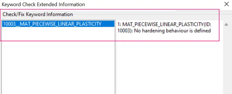
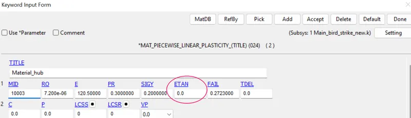
- Opened the material_cards.k file as specified the strain hardening behaviour value as ETAN (Tangent modulus) is 70.
- Debugged the errors in Material data card.
STEP 14 : Run the simulation.
1. To run the simulation by using LS-run by the following steps.
2. Title bar > file > run LS-dyna > runned the k file of main_bird_strike_new > achieved normal temination. it means the model is ready for post processing.
3. During simulation run window will popup as shown in picture below,
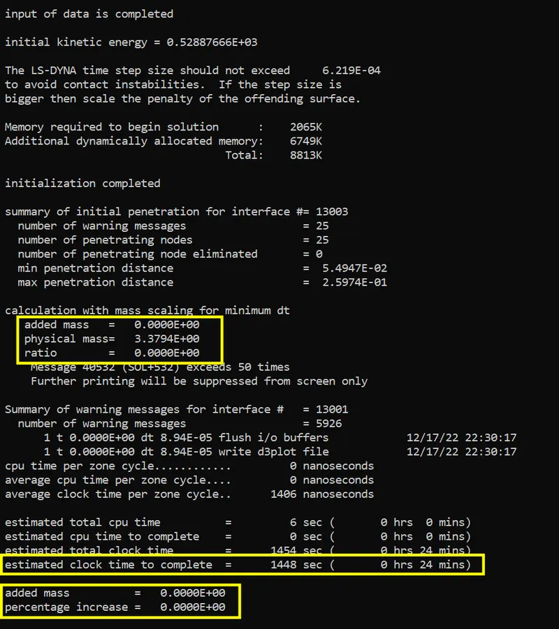
- From this simulation estimated time is little bit higher, so want to reduce the estimated time with increasing the value of DT2MS with achieve hard limit of mass percentage is 8%
| Trial No | Physical Mass (Kg) | TSSFAC | DT2MS (sec) | Added mass (Kg) | Mass percentage increase (%) | Estimated clock time (sec) |
| 1 | 3.3794 | 0.9 | -6.0*e-05 | 0 | 0 | 1440 |
| 2 | 3.3794 | 0.9 | -3.0*e-04 | 6.3*e-02 | 1.86 | 480 |
| 3 | 3.3794 | 0.9 | -3.5*e-04 | 1.4*e-01 | 4.33 | 360 |
| 4 | 3.3794 | 0.9 | -3.7*e-04 | 1.9*e-01 | 5.68 | 300 |
| 5 | 3.3794 | 0.9 | -3.75*e-04 | 2.04*e-01 | 6.05 | 300 |
| 6 | 3.3794 | 0.9 | -4.0*e-04 | 2.7*e-01 | 8.04 | 300 |
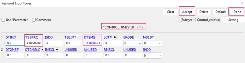
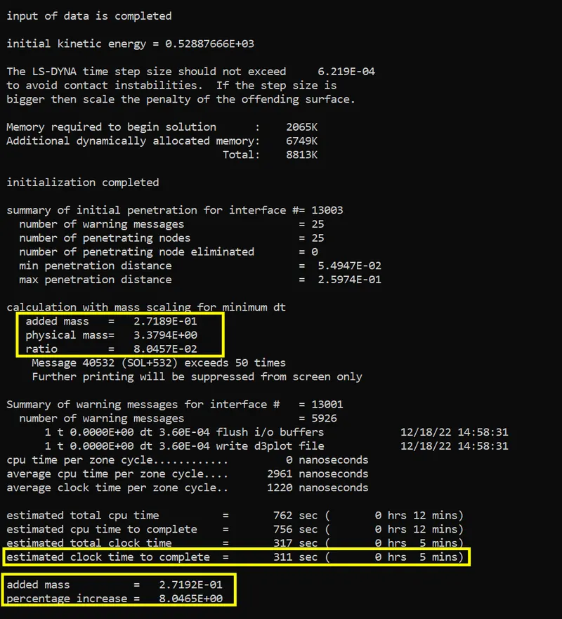
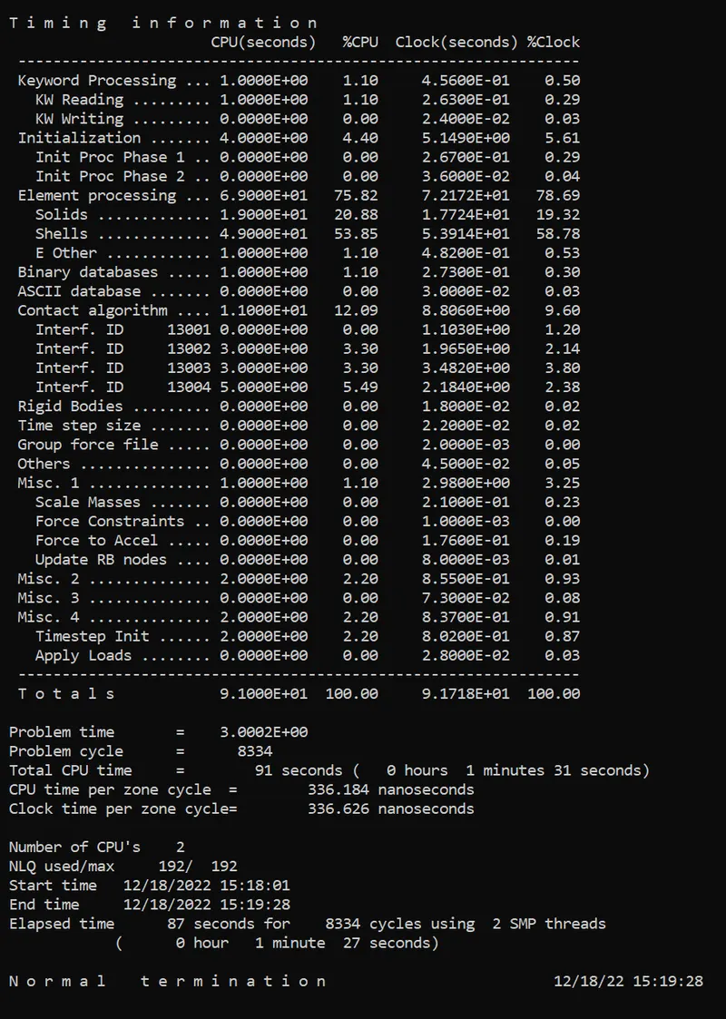
- From trial No-6 we have achieved better mass increase 8% with estimated clock time also reduced to 5 mins (but actual executed time in simulation is 1min 27 secs).
- so DT2MS = -4.0*e-04 and TSSAFC=0.9 was taken as for Control time step is update in Control_cards.K file .
STEP 15 : POST PROCESSING
1. In order to see simulation results , we have to open output file in LS-Prepost by the following steps.
2. In LS-prepost -Title bar > file > open > LS -Dyna binary plot > selected the d3 plot file > visibled to see animation file.
3. For plot the stress contour , go to sidebar > post >fringe component > selected in which results need for analysing the problem.
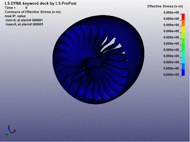
(a) Contour plot of vonmisses stress of bird strike in aero engine blades.
Max effective stress = 0.0857 kg/mm.ms²
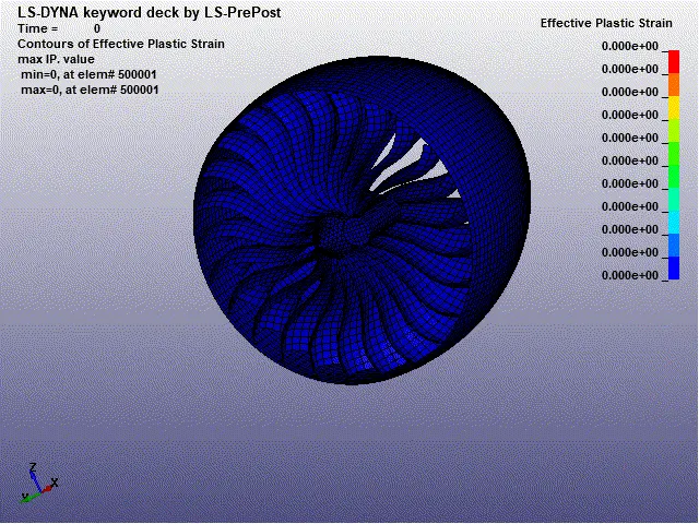
(b) Contour plot of effective plastic strain of bird strike in aero engine blades.
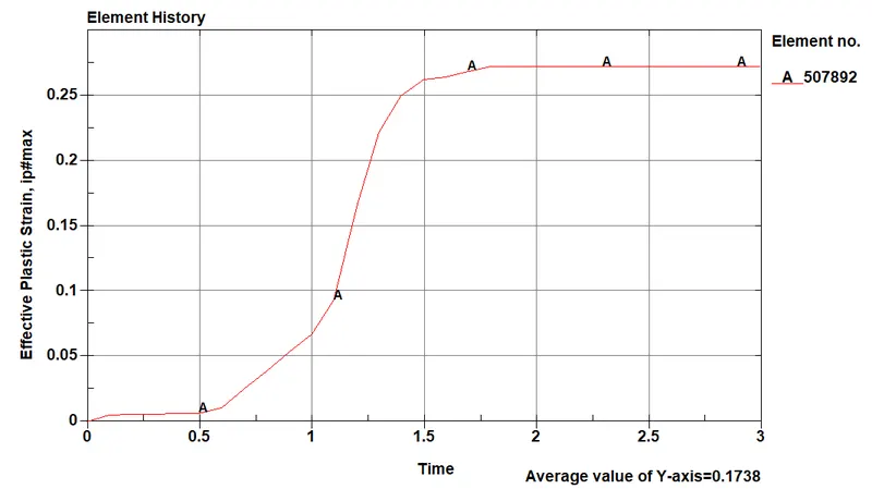
Max effective plastic strain = 0.2723 mm/mm
(c) Energy plots of global statistics data
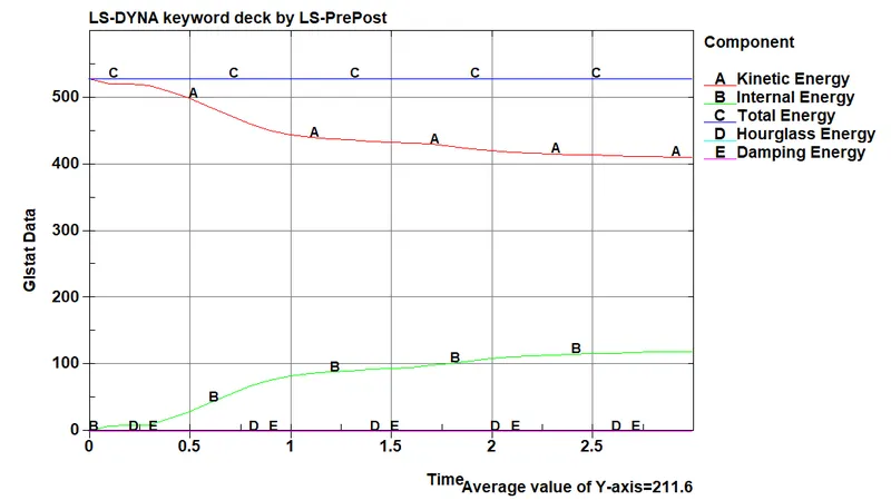
From global statistics data plot,
Max kinetic energy = 528 Kg mm / ms²
Max internal energy = 199.4 Kg mm / ms²
Total energy = 528 Kg mm / ms²
(d) Energy plots of Material energies data
1. Engine blade energy plot
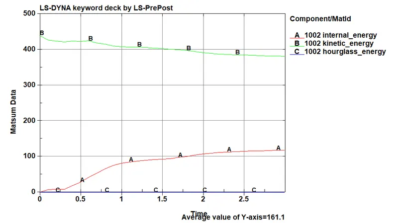
From this plot,
- Engine blade internal energy min = 0 Kg mm / ms²
- Engine blade internal energy Max = 117.93 Kg mm / ms²
- Engine blade Kinetic energy min = 381.14 Kg mm / ms²
- Engine blade Kinetic energy Max = 439.86 Kg mm / ms²
2. Engine Hub energy plot
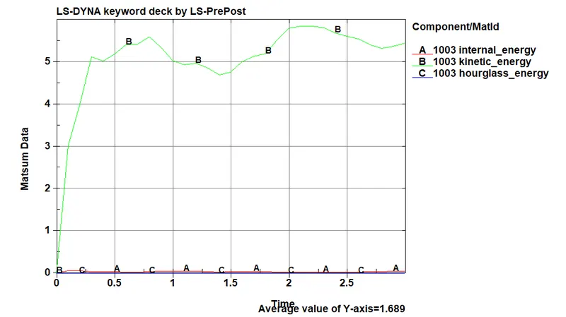
From this plot,
- Engine hub internal energy min = 0 Kg mm / ms²
- Engine hub internal energy Max = 6.86* e-02 Kg mm / ms²
- Engine hub Kinetic energy min = 0 Kg mm / ms²
- Engine hub Kinetic energy Max = 5.84 Kg mm / ms²
3. Bird energy plot
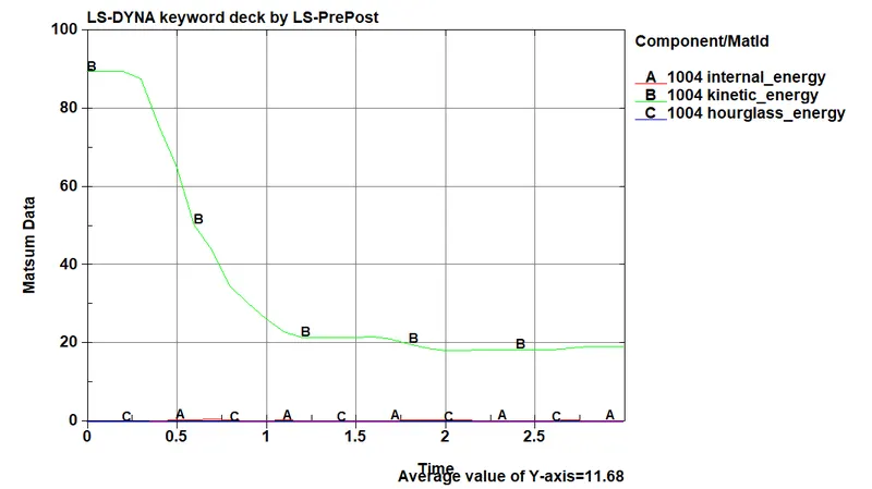
From this plot,
- Bird internal energy min = 0 Kg mm / ms²
- Bird internal energy Max = 6.54* e-01 Kg mm / ms²
- Bird Kinetic energy min = 18.135 Kg mm / ms²
- Bird Kinetic energy Max = 89.5 Kg mm / ms²
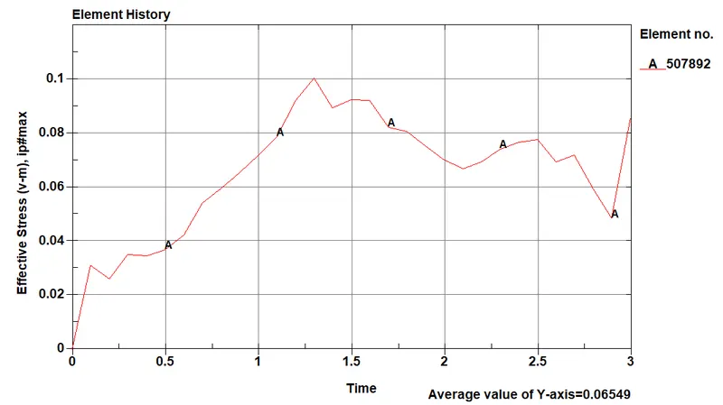
(e) Effective stress Vs time at element 507892 in deformed blade in aero engine
(f) Effective Plastic strain Vs time at element 507892 in deformed blade in aero engine
(g) Effective stress Vs Effective Plastic strain at element 507892 in deformed blade in aero engine
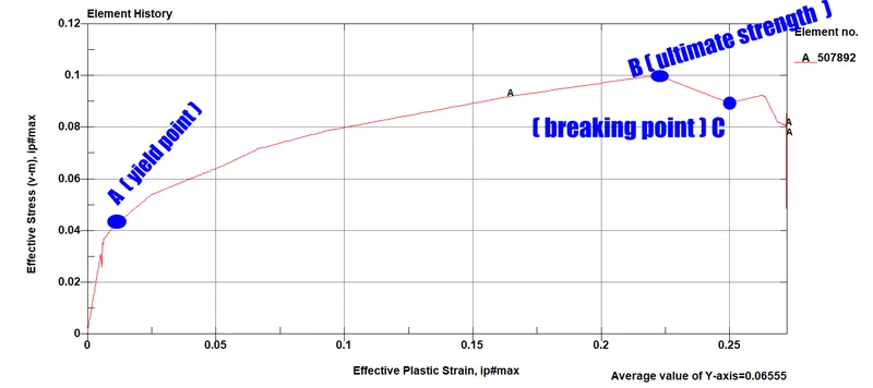
From the above stress Vs strain plot we can understand as reason for the engine blade permanent deformation by analysing the stress Vs strain curve from simulated datas as,
- Bird striked an aero engine blade , result as deformation occurs at the blade is explained as stress and strain plot.
- During bird is striked the blade , stress is directionally proportional to strainwithin Elastic limit, line OA- linear line within the proportional limit .
- After reaching some time at a particular point ,stress is not directly proportional to strain thats means yield point(A). after reaching yield point plastic region starts and end of the elastic region.
- In this plastic region strain occurs in the blade is more , related stress is less.
- In this plastic region deformation ocurred in the blades.
- After bird load against the blade , the maximun stress will be reached -this is an end of the plastic region, this point is ultimate stress(B)
- So while the induced (working) stress is reached beyond the ultimate stress, .
- during bird load against at some point in blades will start to break , because induced (working) stress is reached beyond the ultimate stress(B) blades are cracked , this point is an breaking point(C).
- After reaching this breaking point stress value reduced.
CONCLUSION :
- During bird strike in aero engine blades, max effective stress is 0.0857 kg/mm.ms² and max plastic strain is 0.2723 mm/mm ( 27.23% )
- From the energy plot, we can observe that total energy is constant over the simulation which represents the simulation runs well.
- Durin striking kinetic energy of the blade is vary at that point then decreased the kinetic energy of the blades, so kinetic energy of the blade decreases from 439.86 Kg mm /ms² to 381.14 Kg mm / ms².
- At that same time bird striked into the blades kinetic energy also decreases from 89.5 Kg mm / ms² to 18.135 Kg mm / ms².
- Successfully achieved mass added percentage is 8% which accepted value.
- Exact reason for the aero engine blade failure was analyzed suceessfully.
- Numbering approach of nodes, elements, parts and other relative cards are performed as per given requirements.
- Thus the project was a good learning experience about a complete transient dynamic simulation in LS-Dyna.