Week 3- Geometry cleanup and Mid-surfacing
Geometry cleanup and Mid-surfacing
AIM :
- To extract midsurface and provide connections of the tube and to perform modal analysis of the blocks.
OBJECTIVE :
- To extract mid-surface for the tube model and provide a connection with sharing option at the tube joint locations.
- To Perform a modal analysis of top block with bottom block to verify connections and analyze the results.
DATABASE:
CASE 1:

CASE 2:
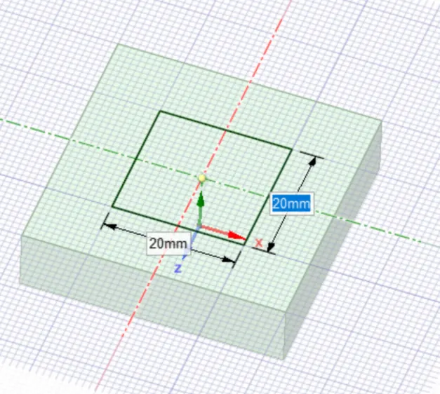
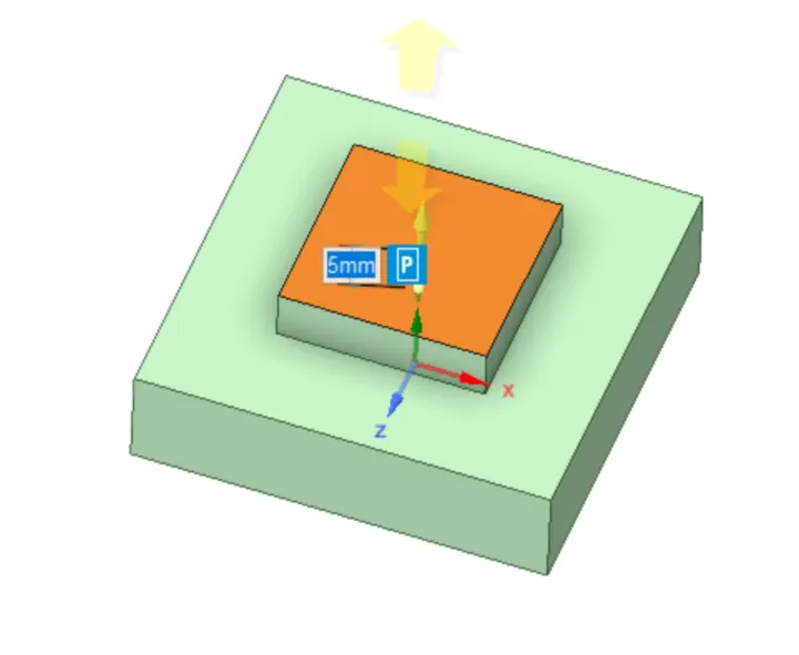
- Dimension of Top Block A: 20 x 20 x 5 mm
- Dimension of Bottom Block B: 40 x 40 x 10 mm
- Boundary Conditions : Provide Fixed support for the bottom face of Block B
SOFTWARE USED :
- ANSYS WORKBENCH -2023RR1
PROCEDURAL STEPS :
CASE 1 : To extract mid-surface for the tube model and provide a connection with sharing option at the tube joint locations.
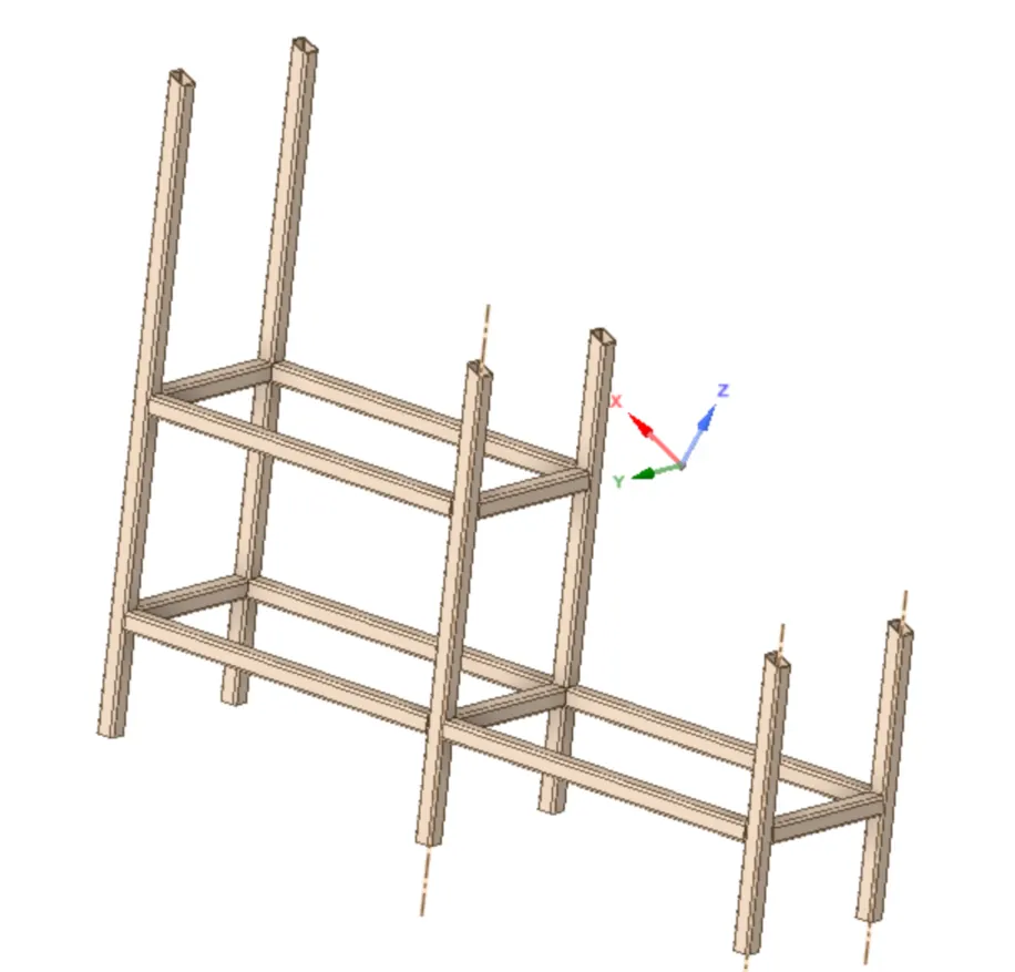
STEP 1 : Import the tube model.
Imported the .scdoc file of the tube model in Ansys space claim Gui.
STEP 2 : To extract the midsurface of the tube model.
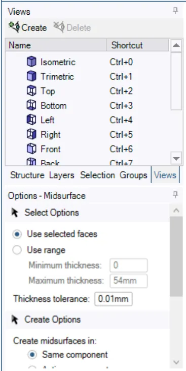
- To extract the midsurface by the following method.
- Thickess of the tube is 2.8 mm , so we have to take midsurface 1.4 mm from the outter surface of the tube.
- Title bar > prepare > Midsurface > checked use selected faces option > selected the faces containing thickness of the tube > done > midsurfaces extracted it from parent geometry.
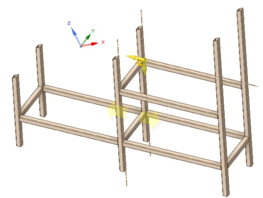
STEP 2 : Extend the faces over one and another of the tubes.
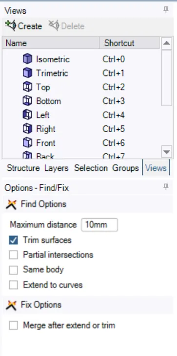
- Inorder to extend the tubes over one and another by the following steps.
- Title bar > prepare > extend > selected the edges > extended it with trimmed surfaces option > done.
STEP 3 : provide a connection with sharing option at the tube joint locations.
- In order to share the tubes over one and another by the following steps.
- Title bar > workbench > share > shared edges found > done.
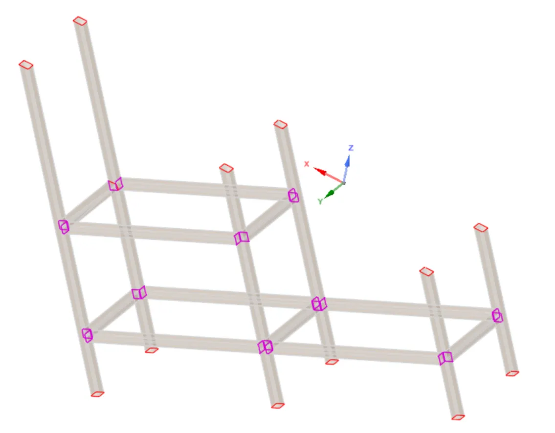
CASE 2 : To Perform a modal analysis of top block with bottom block to verify connections and analyze the results.
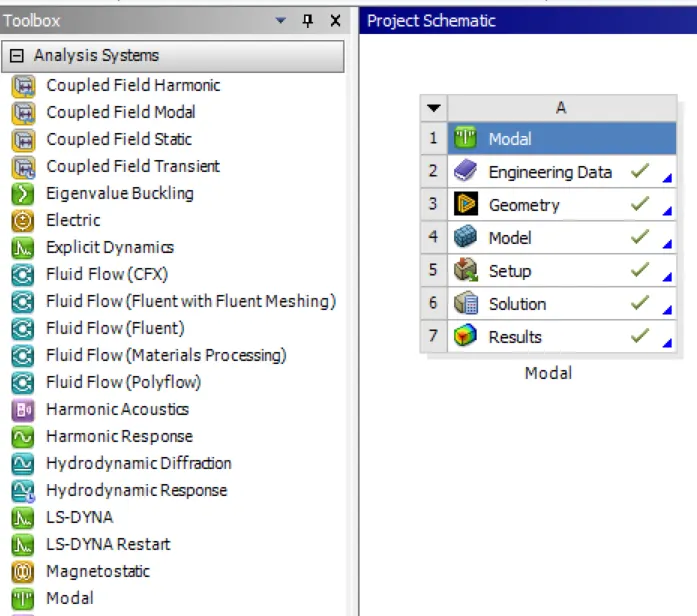
STEP1 : Creatiion of modal analysis project
- In order to create modal analysis project window by the following steps.
- Tool box > analysis system > click on Modal > created modal analysis project tree in window.
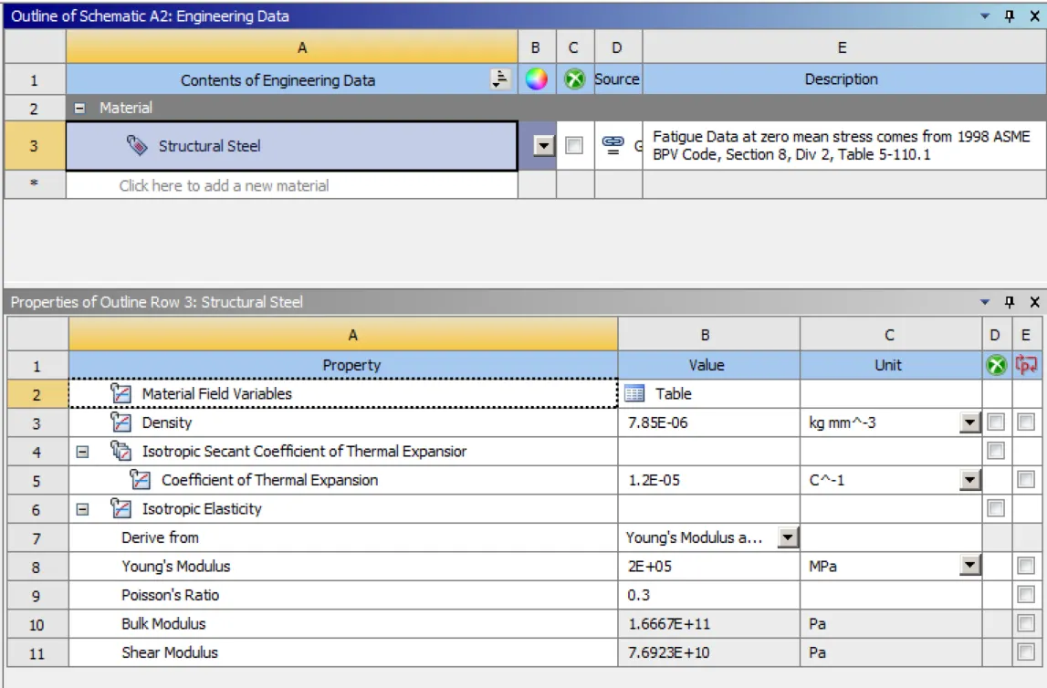
STEP 2 : Selection of material
- Inorder to selection of material by the following steps .
- In modal analysis project tree > engineering data > selected the structural steel material.
STEP 3 : Creation of geometry .
- Inorder to create the geometry by the following steps.
- In modal analysis project tree > RC on geometry > new space claim geometry > opened in space claim GUI.
- To create the bootom block B by the following steps.
- Title bar > sketch > rectangle > checked define rectangle from center > 40 x 40 mm reactangle created.
- Then to give the thickness of the rectangle by the following steps .
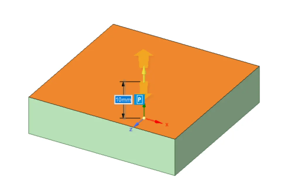
- Tile bar > design > pull > selected the rectangle > pull along its y direction with 10mm length.
Creation of blottom block B ( 40 x 40 x 10 )mm
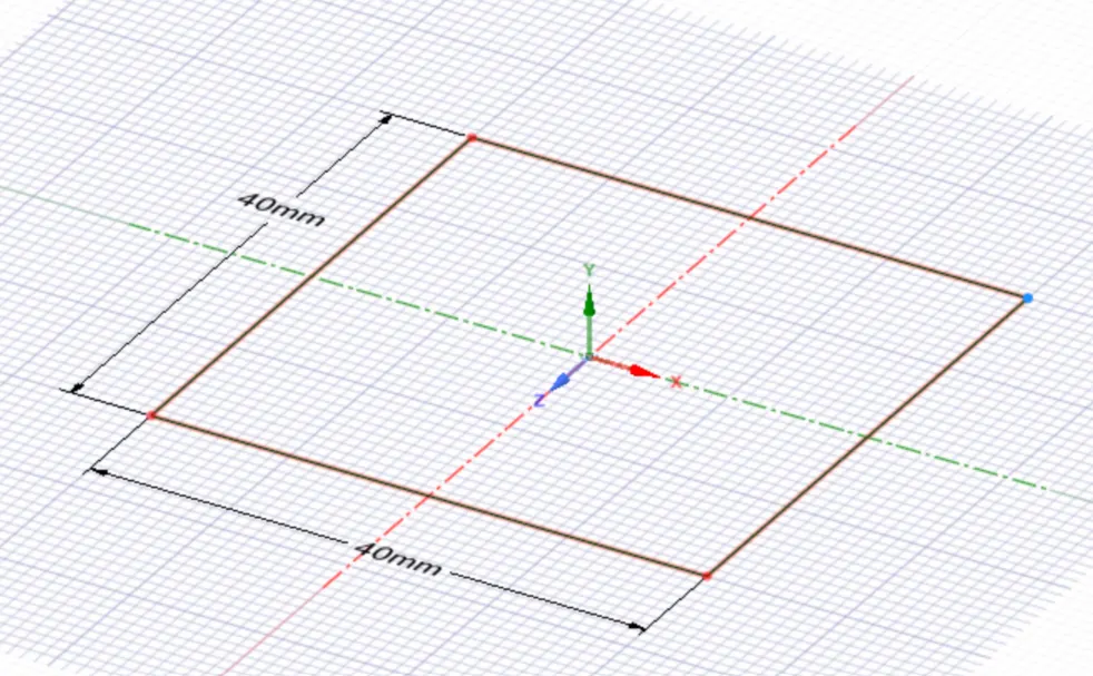
Creation of Top block A ( 20 x 20 x 5 ) mm
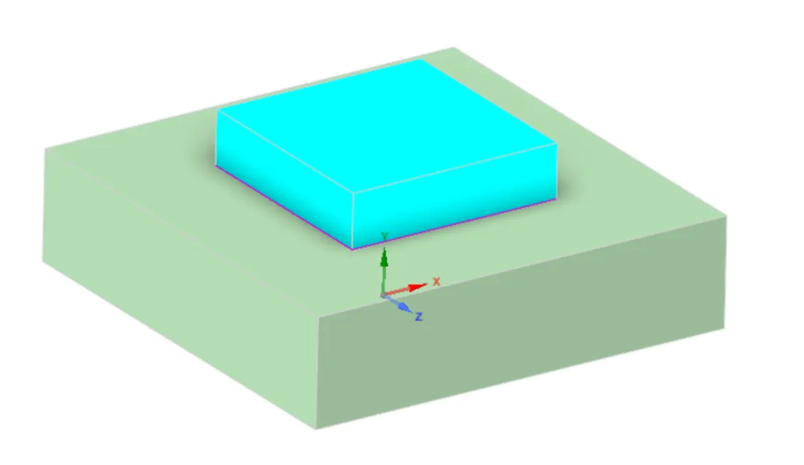
STEP 4 : Split the Blocks.
- Inorder to split tyhe blocks by the following steps.
- Tile bar > design > split body > selected the whole body > then selected the plane which is splitted into two bodies.
Before split
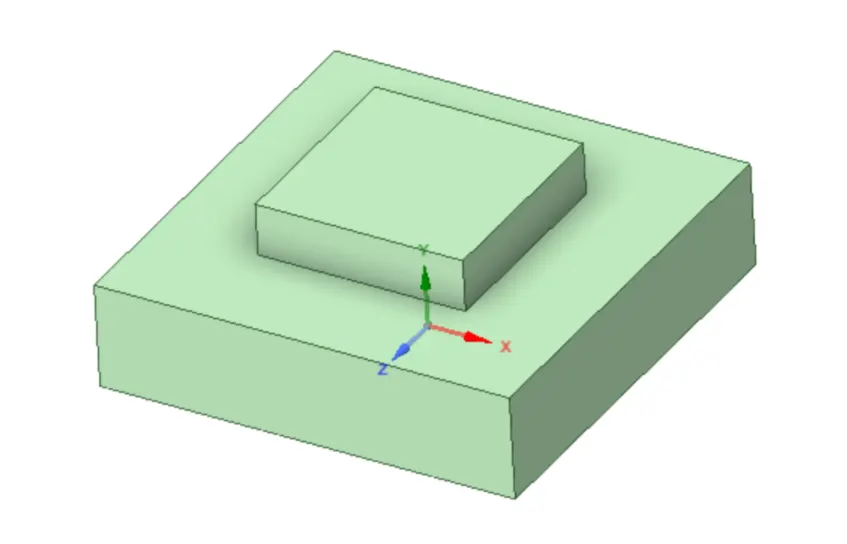
After split
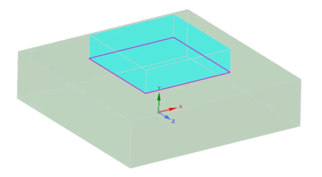
STEP 5 : Provide the connection between the top block and bottom block.
- Inorder to shared the connection between the blocks by the following steps.
- Titlebar > workbench > share > selected the body > Done > shared the edges between the bodies.
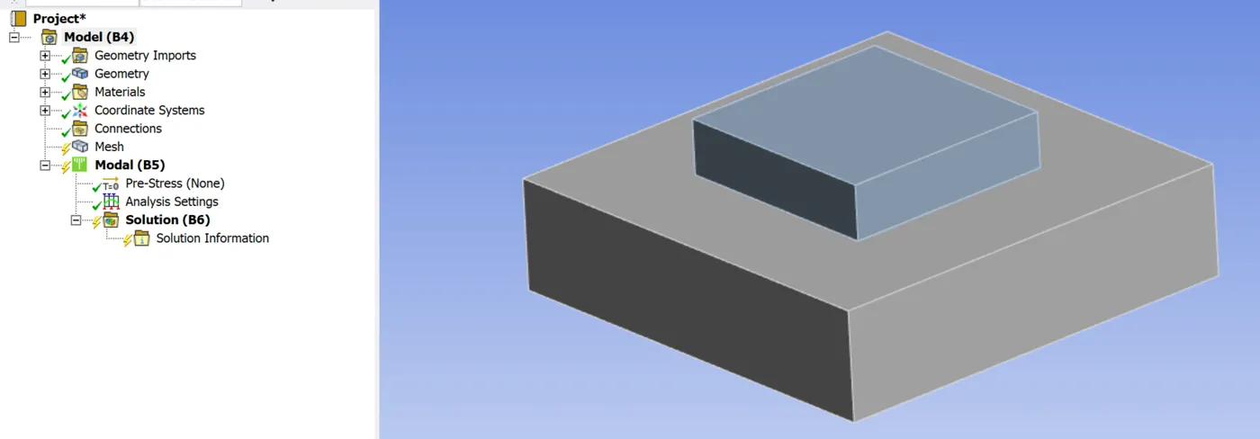
STEP6 : Creation of modal analysis model setup.
- In modal analysis project tree > RC on model > edit > Opened ansys mechanical enetrprise GUI
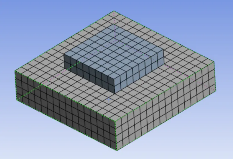
STEP 7 : Meshing of blocks.
- Inorder to meshing of the blocks by the following steps.
- In ansys mechanical > project tree > mesh > method > automatic method > selected the geometry > Hex dominant method > done.
- Project tree > mesh > Sizing > selected the geometry > element size-2.5 mm > done.
- Project tree > mesh > generate mesh > meshed the blocks as shown in below,
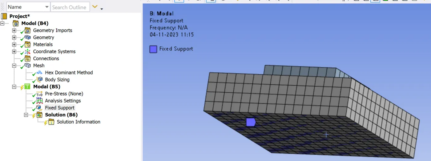
STEP 8 : Set the boundary condition.
- Inorder to Provide the fixed support for the bottom face of Block B by the following steps.
- Project tree >Modal > fixed support > selected rthe botton face of Block B > fixed it.
STEP 9 : Set the Modal analysis settings.
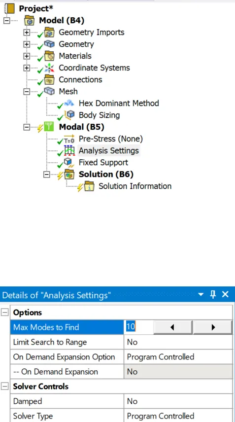
- Inorder to set the modal analysis settings by the following steps.
- Project tree > Modal > analysis settings > max modes to find is 10 >done.
STEP 10 : Solve the problem
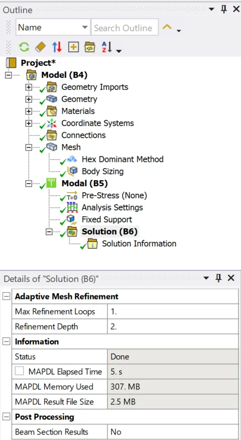
- Inorder to solve the problem by the following steps.
- Project tree > Modal > solution > solve > solved it.
STEP 11 : Post processing.
- In order to get the modeshape results by the following steps.
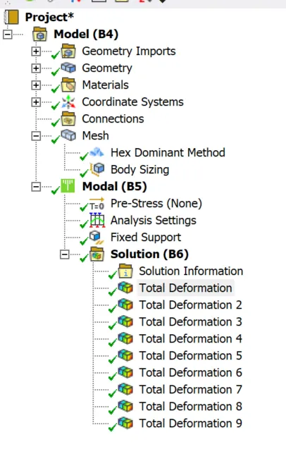
- Selected the datas in frequency table > RC > Create mode shape results from of total deformation >done.
- Then Project tree > solution > RC > evaluate all results.
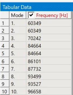
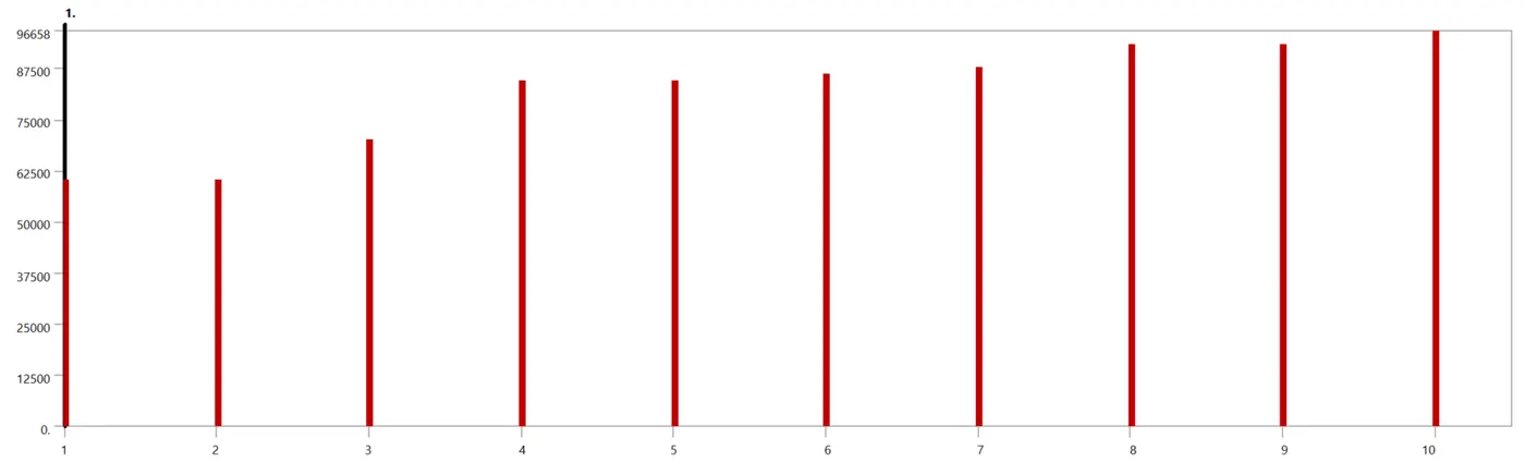
Modes Vs Frequency range
Mode shape results :
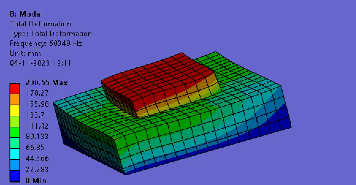
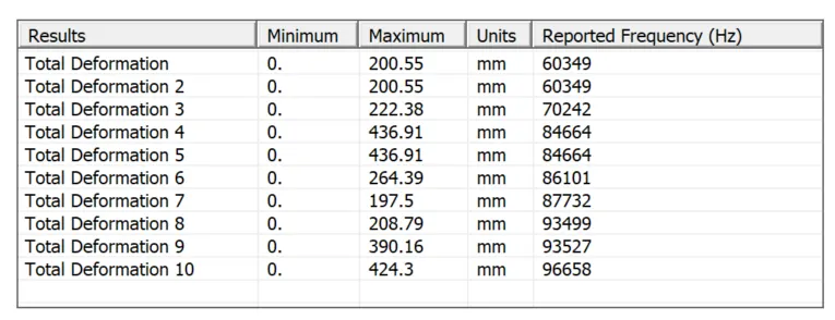
1.) First mode shape .
Frequency - 60349 Hz
Max Total deformation - 200.55 mm
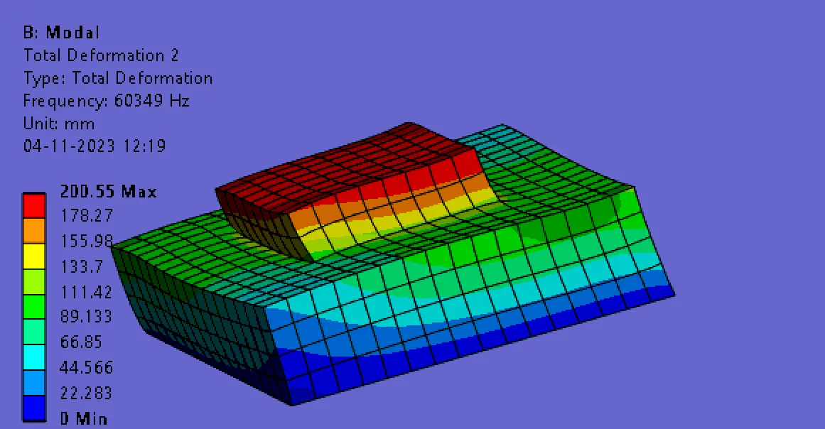
2.) Second mode shape .
Frequency - 60349 Hz
Max Total deformation - 200.55 mm
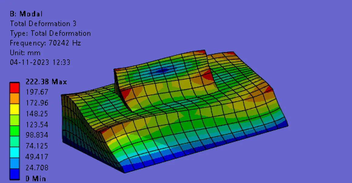
3.) Third mode shape .
Frequency - 70242 Hz
Max Total deformation - 222.38 mm
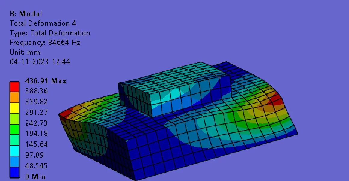
4.) Fourth mode shape .
Frequency - 84664 Hz
Max Total deformation - 436.91 mm
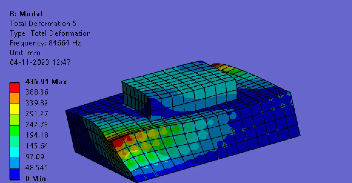
5.) Fifth mode shape .
Frequency - 84664 Hz
Max Total deformation - 436.91 mm.
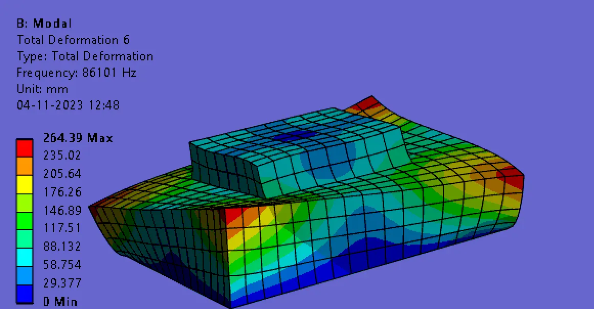
6.) Sixth mode shape .
Frequency - 86101 Hz
Max Total deformation - 264.39 mm.
7.) Seventh mode shape .
Frequency - 87732 Hz
Max Total deformation - 197.5 mm.
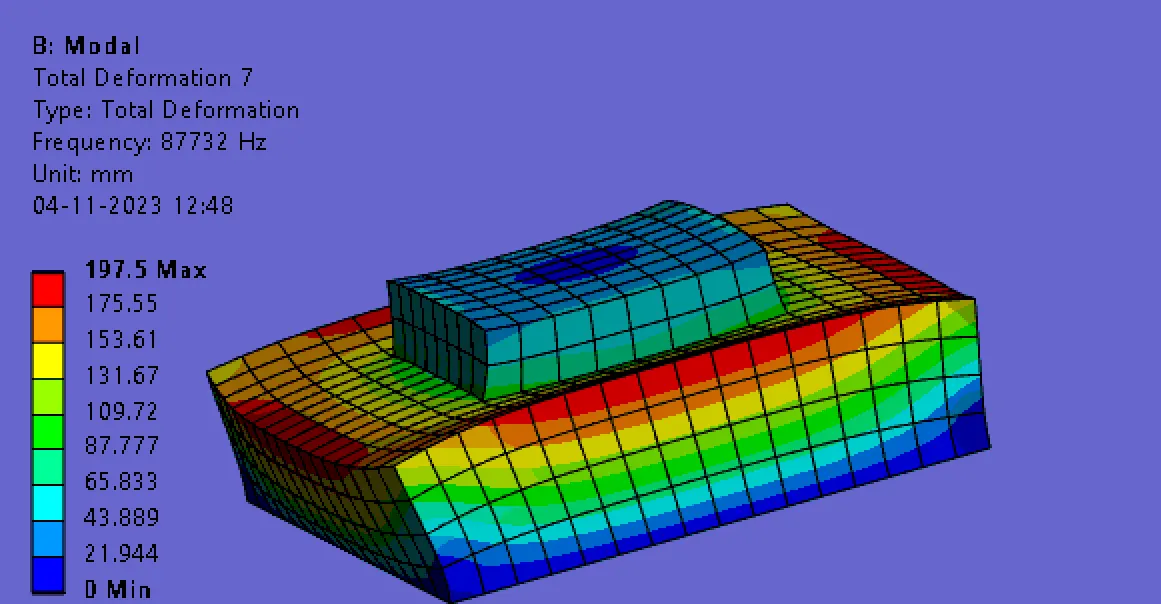
8.) Eigth mode shape .
Frequency - 93499 Hz
Max Total deformation - 208.79 mm.
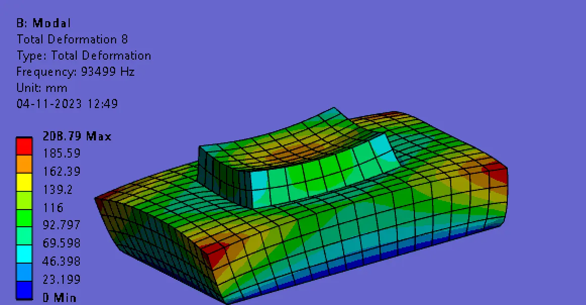
9.) Ninth mode shape .
Frequency - 93527 Hz
Max Total deformation - 390.16 mm.
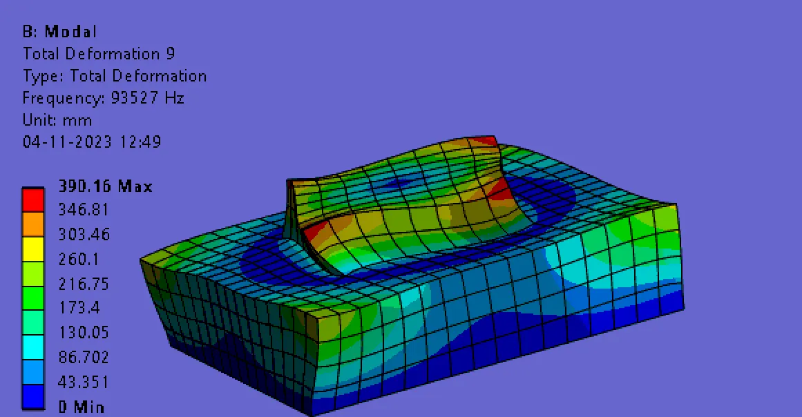
10.) Tenth mode shape.
Frequency - 96658 Hz
Max Total deformation - 424.3 mm.
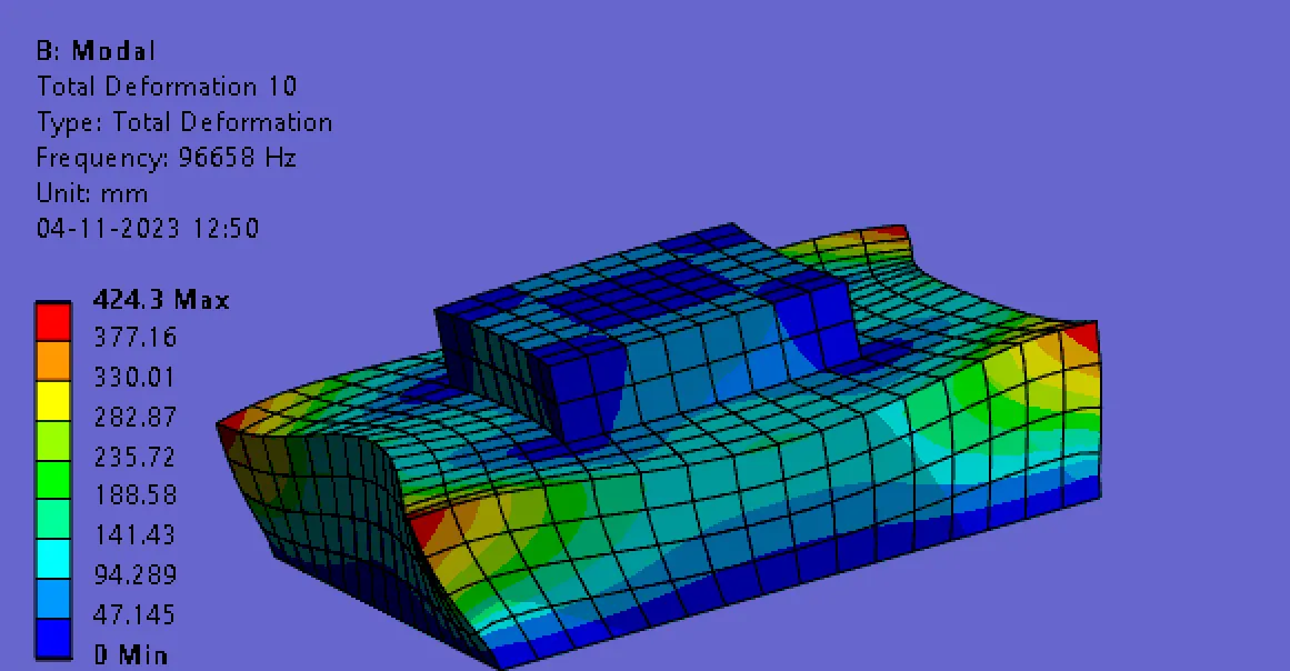
Comparison of Modal analysis result:
From the results,
- Max frequency is 96658 Hz occured at modeshape 10 with relevant deformation is 424.3 mm.
- Max deformation occured is 436.91 mm at mode shape 4 and 5 with relevent natural frequency is 84664 Hz.
- Initial modeshapes 1 & 2 only get the min frrquencies with relevent deformtion is 200.55 mm.
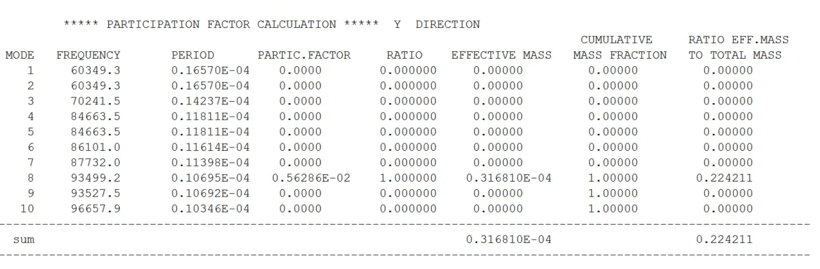
- For translational y direction modeshape 8 only have min values of participation factor , effective masses and cumulative mass fraction and effective mass to total mass of the block.
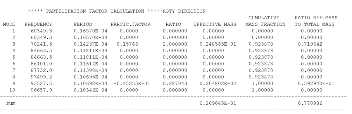
- For Rotational y direction modeshape 3 and 9 only have min values of participation factor , effective masses and cumulative mass fraction and effective mass to total mass of the block.
Conclusion :
- In Mid-surface for the tube model have each and every tube was well shared to the adjacent tubes.
- Geometrically Shared BlockA and Block B successfully.
- Modeshapes, total deformations and its related frequencies has been found out.
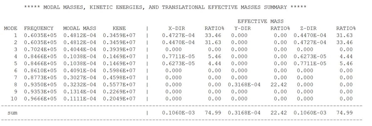
- Modal participation fator and effective masses are found out for the different modeshapes of the blocks.
Learning outcome :
- How to do extract midsurface and splitbody and shared options in space claim.
- How to create geometry in space claim.
- How to define engineering data, meshing, model setup and post processing in ansys workbench