Week-6 Calculate the Stretch Ratio by comparing the ELFORM (-2,-1,1,2) with Ogden_Material Model.
CALCULATION OF STRETCH RATIO BY THE SIMULATION OF OGDEN MATERIAL BLOCK MODEL WITH ELFORM 1,2,-1,-2
AIM :
- To create a tensile load simulation using the Ls – Dyna and to find the engineering stress and strain and stretch ratio.
- To calculate the stretch ratio by comparing the ELFORM (-2,-1,1,2) with Ogden Material Model.
OBJECTIVE :
- To create the cube and add the given ogden material property and solid section to the cube.
- To create the constraints and displacement for the cube.
- To create the implicit control cards for the cube model and run the simulation.
- To extract the true stress and strain values and calculate the engineering stress and strain.
- To plot the graph using Normal stress and Stretch ratio in excel software.
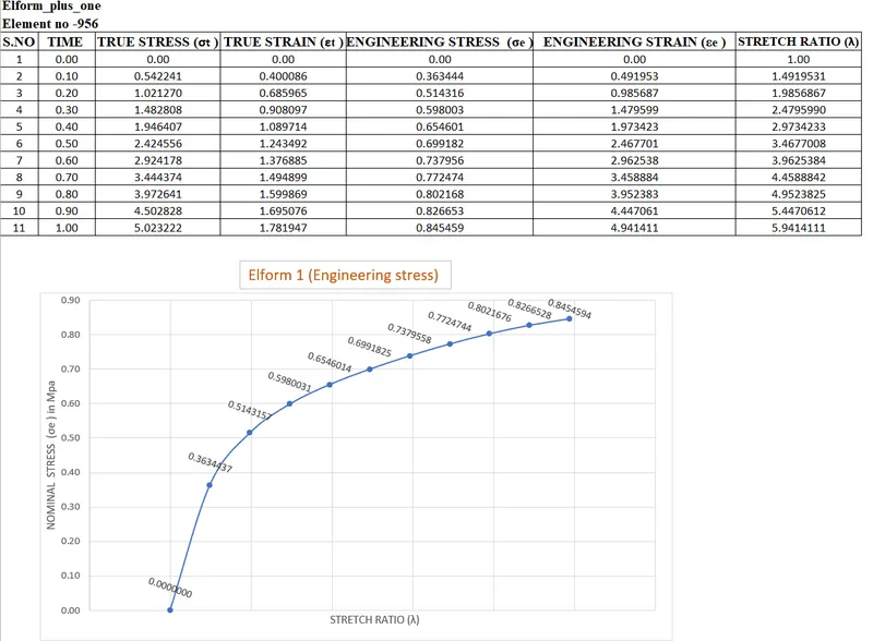
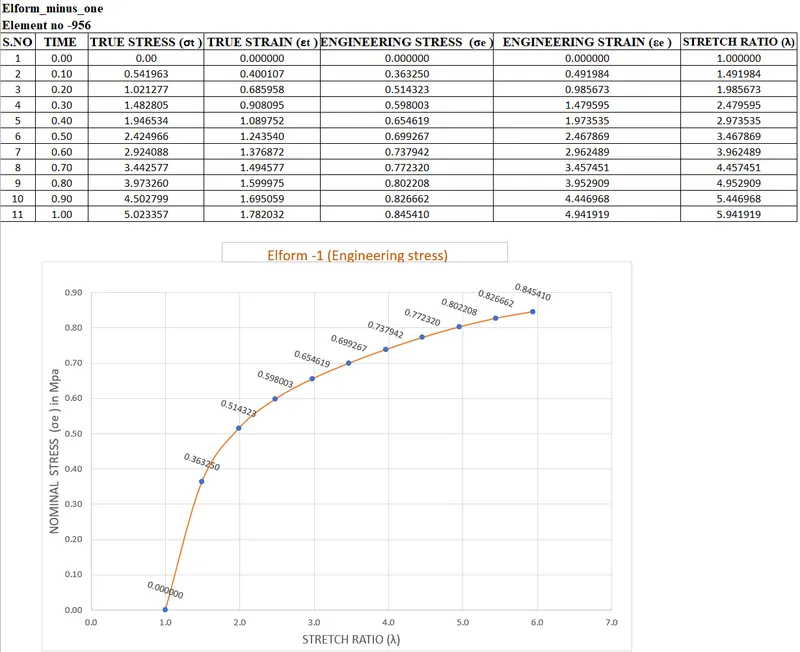
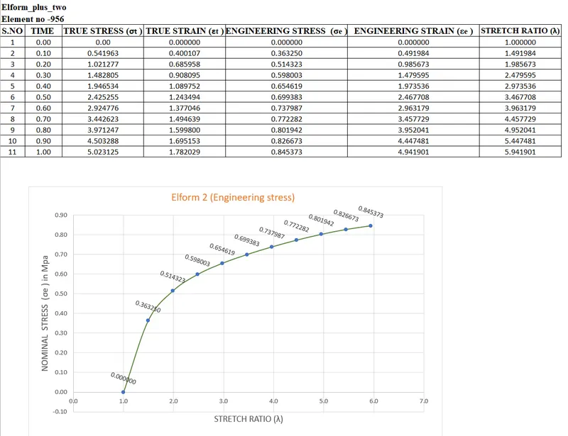
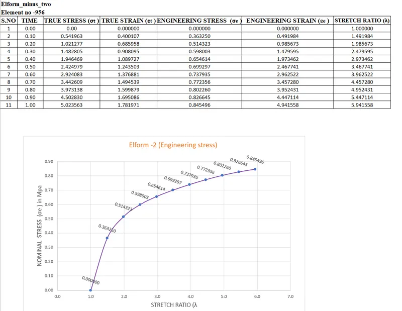
- To simulate the tensile behavior for the model and finally compare the results for the simulation using ELFORM (1, 2, -1, -2 ) to the nominal stress Vs stretch ratio plot for upto stretch ratio 5
DATA BASE :
- LS-DYNA the output of stress and strains from Post FringeComp Stress/Strain is given as true stress and strains.
- Stretch ratio l is defined as the ratio between the final length L and the initial length L0 of a component i.e. it is equal to (1 + engineering strain)
- Boundary condition should be relatable with the real-time boundary condition.
- Add *Database_Extend_Binary card and activate the STRFLG to get the strain data.
DELIVERABLES:
- An excel sheet with proper conversion and calculation of Stress/Strain and the Stretch Ratio for all the ELFORM.
- A proper image of the plot comparison of various ELFORMS against the Uniaxial Plot given in the challenge.
- Element formulations used are 1,-1,2,-2 for solids.
- In this challenge, we shall be comparing the results of 4 cases, differentiated by the type of element formulation used:
Case 1 - ELFORM 1: constant stress solid element.
Case 2 - ELFORM -1: Fully integrated S/R solid intended for elements with poor aspect ratio, efficient formulation.
Case 3 - ELFORM 2, Fully integrated S/R solid.
Case 4 - ELFORM -2, Fully integrated S/R solid intended for elements with poor aspect ratio, accurate formulation.
SOFTWARE USED :
- Solver tool - LS-Prepost 4.7.17 & LS-Run 1.0.100838.
BACKGROUND :
- The Ogden material model is a hyperelastic material model used to describe the non-linear stress-strain behaviour of complex materials such as rubbers and biological tissue.
- The model was developed by Raymond Ogden in 1972. The model relies on the fact that the material behaviour can be described by means of a strain energy density function, whence the stress-strain relationships can be derived.
- The Ogden model is often used to model rubberlike materials such as polymers, and biological materials. These materials can generally be considered to be isotropic, incompressible and strain rate independent.
- Since this simulation is happening at a really slow pace (quasi static) the inertial effects can be neglected, so explicit method we cant able to solve this problem ,so we can consider to solve this problem as implicit for the analysis.
- Since this a hyperelastic material even though we are running it in implicit , we need steps and iterations to achieve the equilibruim.
PROCEDURAL STEPS :
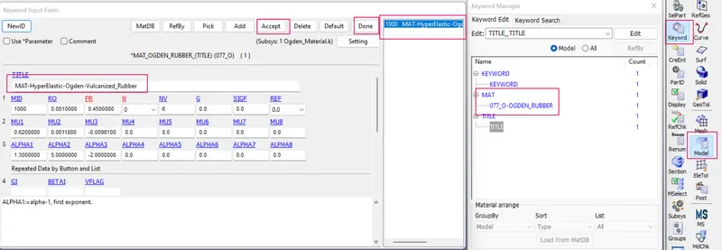
STEP 1 : IMPORT THE K FILE OF OGDEN MATERIAL.
- Imported the K format type of file using LS-Prepost software.
- File > Import > LS-Dyna keyword file > browsed to selected the K type of file > imported it.
- Checked the ogden material card keyword datas by the following steps.
- Side bar > model > keyword > MAT > 077_OGDEN _RUBBER.
STEP 2 : CREATION OF BLOCK.
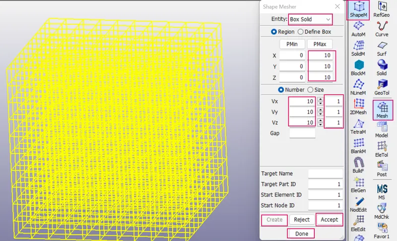
- Created the block with mesh elements by the following steps
- Side bar > element and mesh > shape mesher > selected entity as a box solid > specified dimensions as per the give data > accept and done.
STEP 3 : CREATION OF SECTION SOLID FOR THE BLOCK
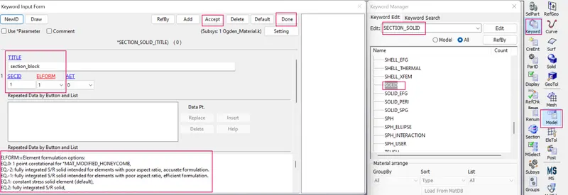
- Created the section solid to the block by the following steps.
- Side bar > model > keyword manager > section > solid > specified title, ID and ELFORM IS 1 > accept and done.
STEP 4 : ASSIGN THE MATERIAL CARD AND SECTION CARD TO THE BLOCK PART CARD.
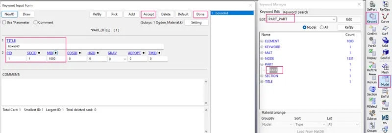
- Assigned the material card and section card to the block part card by the foolowing steps.
- Side bar > model > keyword manager > part > solid > assigned the material card (MID) and section card (SECID) > accept and done.
STEP 5 : CREATION OF BOUNDARY CONDITION FOR THE BLOCK.
- Created the constraint by the following steps.
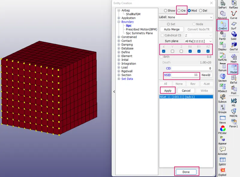
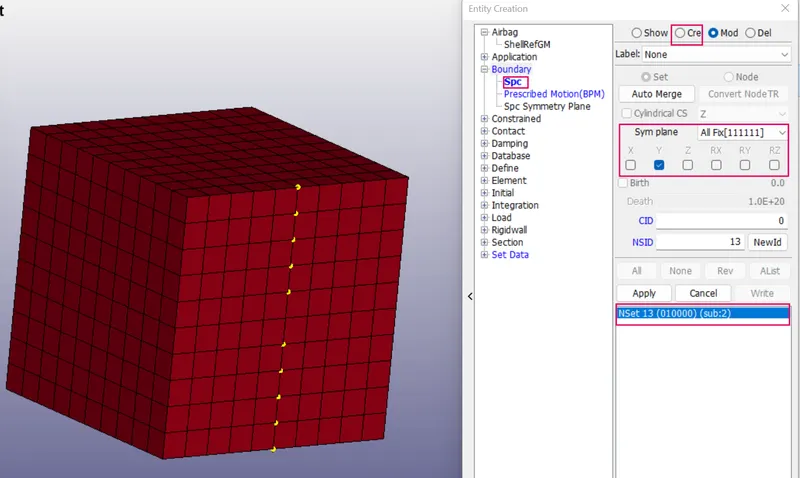
- Side bar > model > create entity > boundary > spc > create >selected the nodes by pick > set > symm plane is constrained in x direction > created new NSID > apply and done.
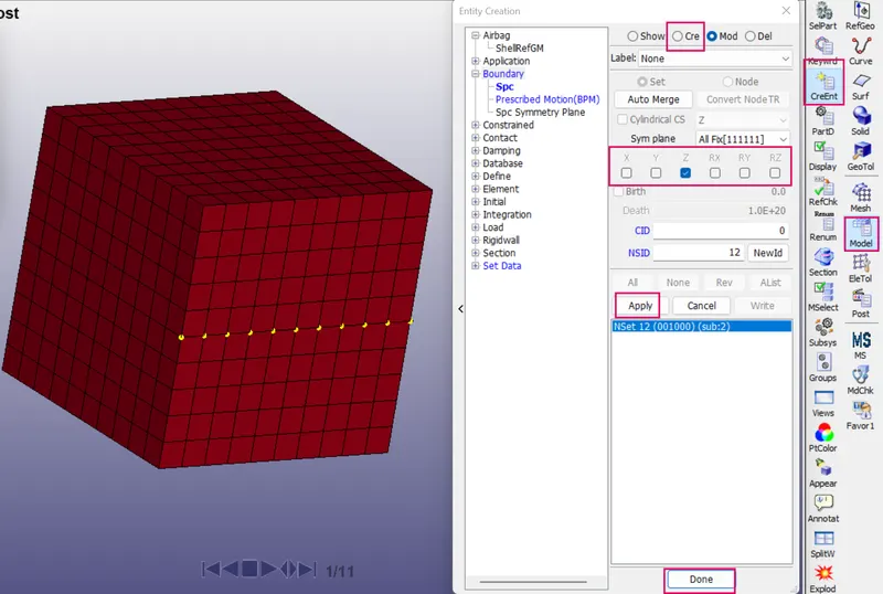
- Similarly Side bar > model > create entity > boundary > spc > create >selected the nodes by pick > set > symm plane is constrained in y direction > created new NSID > apply and done.
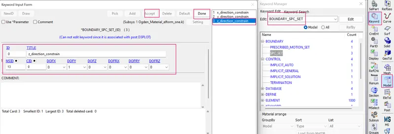
- Similarly Side bar > model > create entity > boundary > spc > create >selected the nodes by pick > set > symm plane is constrained in z direction > created new NSID > apply and done.
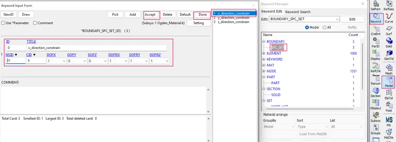
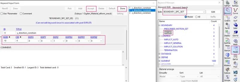
- Then checked the created nodeset ids in keyword manager > boundary > spc > checked automatically assigned the nodeset ids to the relative boundary condition.
Constrained BC in X direction
Constrained BC in Y direction
Constrained BC in Z direction
STEP 6 : CREATION OF CURVE AND PRESCRIBED MOTION BOUNDARY TO THE BLOCK.
STEP 6A : DEFINE A CURVE
- Next, Assign the prescribed motion boundary condition to the opposite side of the box.
- We shall be utilizing the displacement variant of the condition.
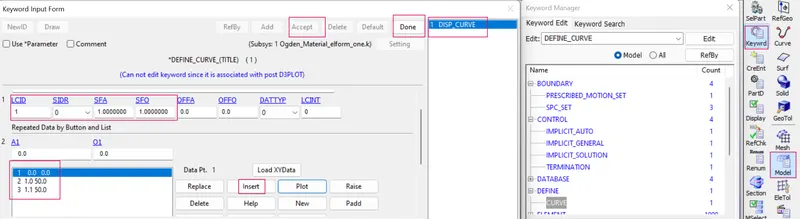
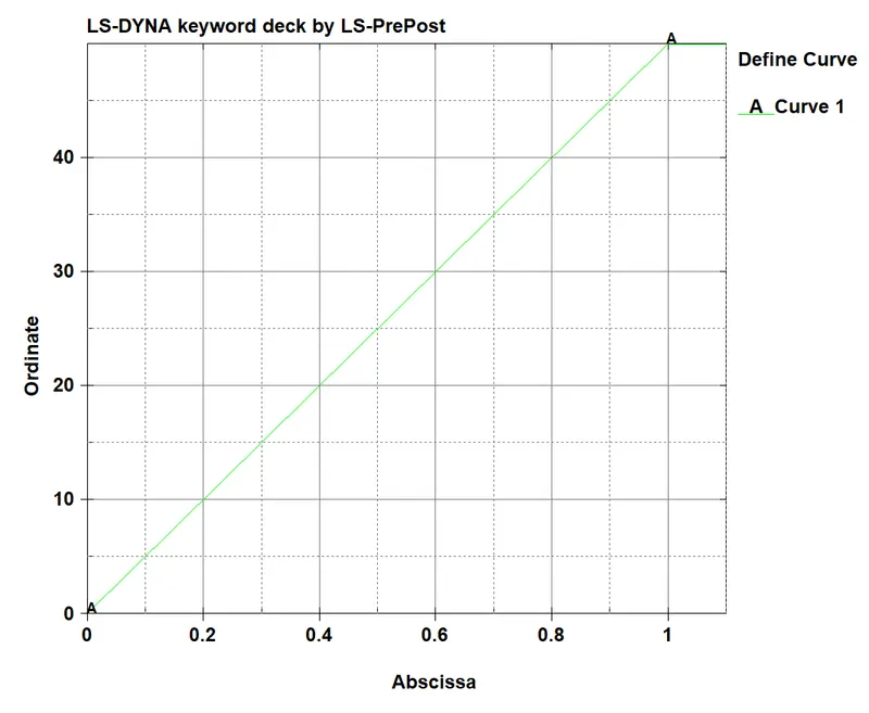
- Define a BPM, a curve needs to be defined.
- Defined one based on the stretch ratio is 5.
Stretch ratio = 1 + engineering strain
5 = 1+(Displacement / Original length )
5 = 1 + (Displacement / 10 )
Displacement = 40 mm
So the face is to be displaced by a minimum of 40mm.
- Define the curve by the following steps.
- Side bar > model > keyword manager > define > curve > specified the coordinated as per requirement > accept and done.
STEP 6A : CREATION OF PRESCRIBED BOUNDARY CONDITION.
- Before create a precribed BC we have to create a new nodeset ids for displacement .
- Created the new node set ids by the following steps.
- Side bar > model > create entity > set data > set node > selected the nodes of the opposite side of block > apply.
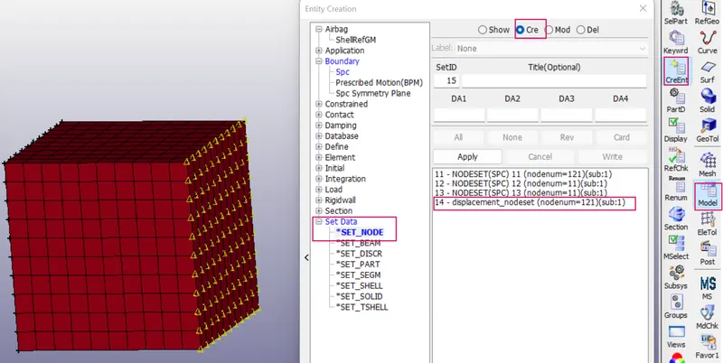
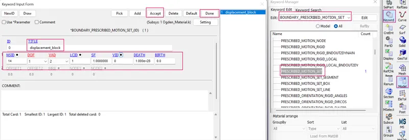
- Now go to create the prescribed boundary condition by the following steps.
- Side bar > model > keyword manager > all > prescribed motion set id > assigned the created displacement nodeset id > assigned the created displacement curve > accept and done.
STEP 7 : CREATION OF CONTROL CARDS
STEP 7A : CREATION OF CONTROL TERMINATION CARD.
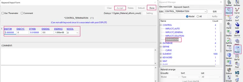
1.The main purpose of control termination card is to stop the job.
2. In order to assign the control termination card by the following steps.
3. Side bar > model and part > keyword manager > control > termination > specify termination time is 10 ms > aceept and done.
STEP 7B : CREATION OF CONTROL IMPLICIT CARDS
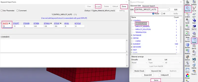
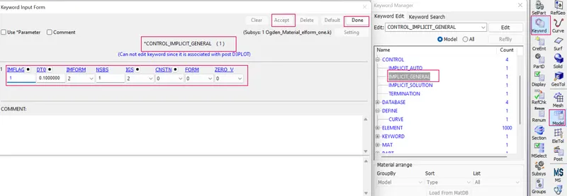
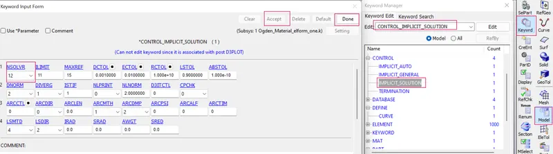
- It is nonlinear implicit analysis we need to create implicit cards like implicit auto, implicit general and implicit solution and control termination for the model.
- In order to create the implicit cards by the following steps.
- Side bar > model and part > keyword manager > control > IMPLICIT_AUTO >specified the required values as per requirement > aceept and done.
- Side bar > model and part > keyword manager > control > IMPLICIT_GENERAL >specified the required values as per requirement > aceept and done.
- Side bar > model and part > keyword manager > control > IMPLICIT_SOLUTION >specified the required values as per requirement > aceept and done.
STEP 8 : CREATION OF DATABASE CARDS.
STEP 8A : CREATION OF OUTPUT DATABASE AS EXTEND BINARY .
- Now we have everything for the simulation but to extract the results we need to create a database cards for the model.
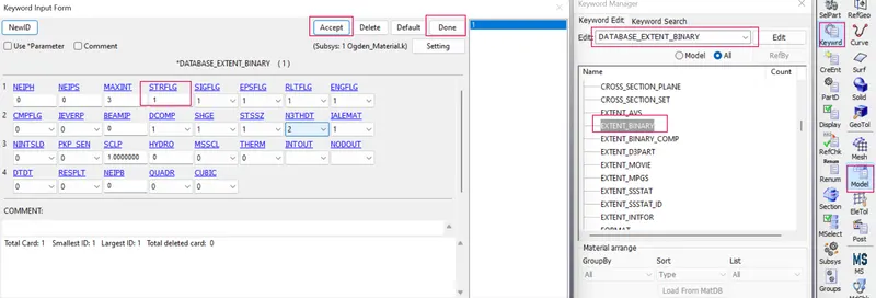
- We also need to generate the strain outputs. To do that, we can create a keyword by going to Keyword manager and selecting DATABASE > EXTENT_BINARY.
- To create the database extend binary card by the following steps,
- Side bar > model > keyword manager > all > DATABASE > EXTEND_BINARY> and give STRFLG as ‘1’, this is due to extract the true strain values for the model and accept the card.
STEP 8B : CREATION OF OUTPUT DATABASE AS BINARY D3 PLOT
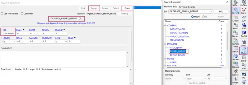
1. DATABASE_BINARY_D3PLOT ensures d3 plot files which its stores stress strain contour of the entire deformed model.
2. In order to create the DATABASE_BINARY_D3PLOT by the fllowing steps.
3. Side bar > model and part > keyword manager > database > select DATABASE_BINARY_D3PLOT > provide DT value is 0.1 is a time interval between output states > accept & done.
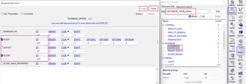
STEP 8C : CREATION OF OUTPUT DATABASE AS ASCII OPTION.
1. ASCII can generate different outputs such as force generated in a contact like total energy and material energy etc.
2. In which we will request output as GLSTAT, MATSUM,SECFORCE, SLEOUT, and RCFORCE.
3. In order to create the ASCII by the fllowing steps.
4. Side bar > model and part > keyword manager > database > select ASCII_option > check GLSTAT,MATSUM ,NODOUT> specify all value is 0.1>accept & done
STEP 9 : MODEL CHECKUP AND RUN THE SIMULATION
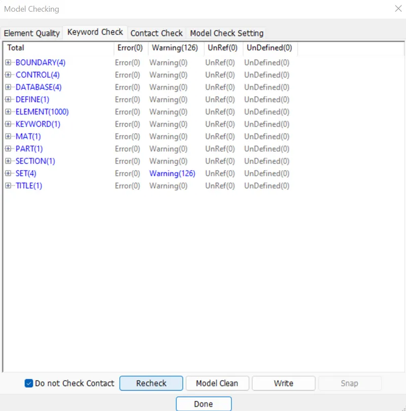
1. The model is checked for any errors before solving using model checker.
2. After all the errors are cleared, the drop test setup is saved and is ready to run in LS DYNA manager for solving the scenario.
3. Warnings we can ignore ,once model check is run , it will look like as shown in picture below.
STEP 10 : RUN THE SIMULATION
1.. To run the beam_spotweld_bracket using LS-run by the following steps.
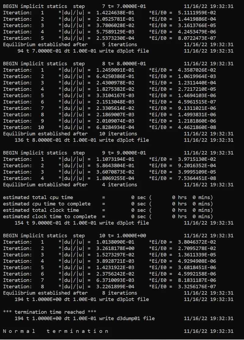
2. Title bar > file > run LS-dyna > runned the Ogden_Material_elform_one file > achieved normal temination. it means the model is ready for post processing.
3. During simulation run window will popup as shown in picture below,
STEP 11 : CREATION OF SECTION SOLID CARD FOR ELEMENT FORMULATIONS -1,+2 & -2
- Similarly created the section solid to the block for element formulation -1,+2,-2 by the following steps.
- Side bar > model > keyword manager > section > solid > specified title, ID and ELFORM IS -1 > accept and done.
- save as the keyword file as other names.
STEP 12 : POST PROCESSING
1. In order to see simulation results , we have to open output file in LS-Prepost by the following steps.
2. In LS-prepost -Title bar > file > open > LS -Dyna binary plot > selected the d3 plot file > visibled to see animation file.
3. For plot the stress contour , go to sidebar > post >fringe component > selected in which results need for analysing the problem.
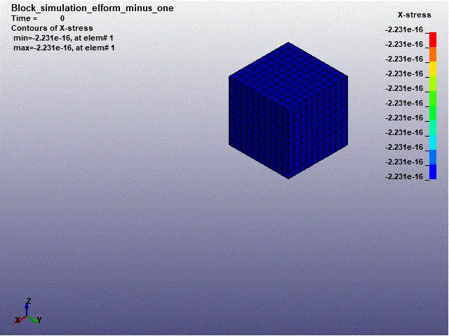
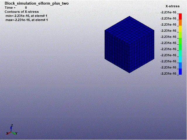
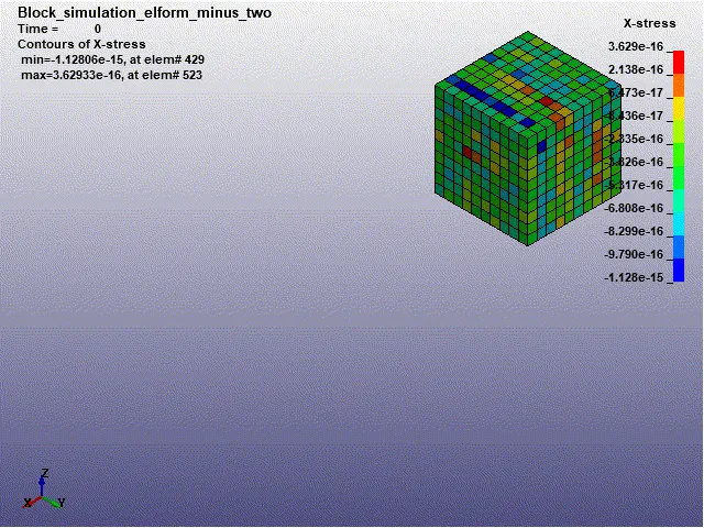
STEP 12 A : CONTOUR PLOT OF X-STRESS WITH ELFORM 1,-1,2&-2
In order to see simulation results, we have to open output file .d3plot file in LS-PrePost
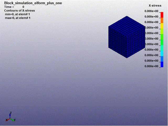
CASE 1 :CONTOUR PLOT OF X-STRESS WITH ELFORM (1)
Max X-stress = 5.02781 Mpa
CASE 2 :CONTOUR PLOT OF X-STRESS WITH ELFORM (-1)
Max X-stress = 5.02558 Mpa
CASE 3 :CONTOUR PLOT OF X-STRESS WITH ELFORM (2)
Max X-stress = 5.02345 Mpa
CASE 4 :CONTOUR PLOT OF X-STRESS WITH ELFORM (-2)
Max X-stress = 5.02475 Mpa
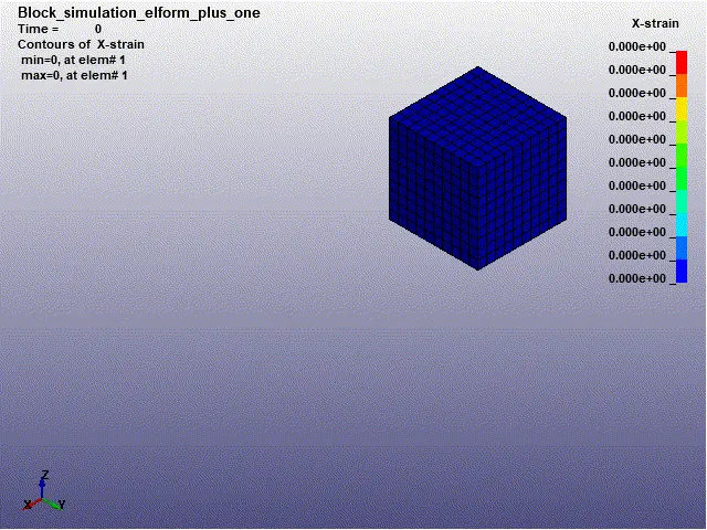
STEP 12 B : CONTOUR PLOT OF X-STRAIN WITH ELFORM 1,-1,2&-2
CASE 2 : CONTOUR PLOT OF X-STRAIN WITH ELFORM (1)
Max X-strain = 1.78252
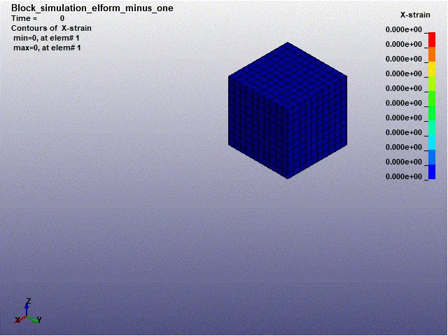
CASE 2 :CONTOUR PLOT OF X-STRAIN WITH ELFORM (-1)
Max X-strain = 1.78236
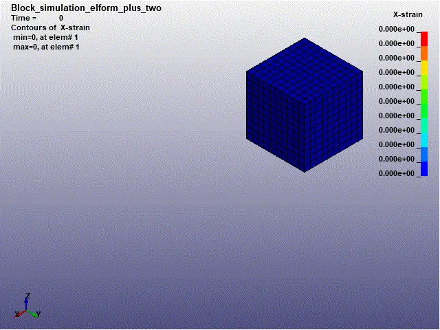
CASE 3 :CONTOUR PLOT OF X-STRAIN WITH ELFORM (2)
Max X-strain = 1.78211
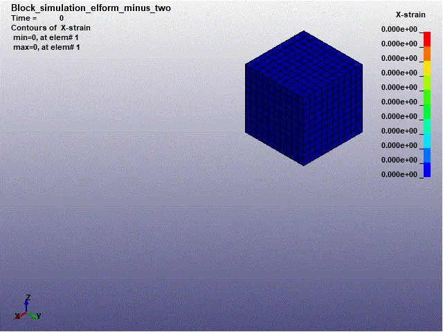
CASE 4 :CONTOUR PLOT OF X-STRAIN WITH ELFORM (-2)
Max X-strain = 1.78215
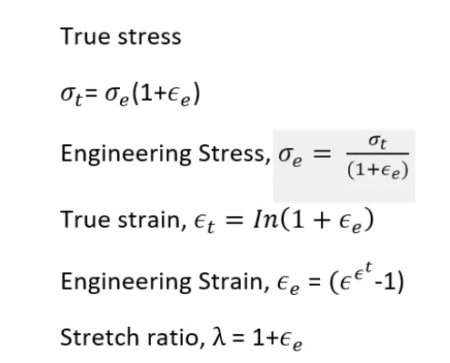
STEP 13 : CALCULATION OF ENGINNERING STRESS AND STRAIN FROM TRUE STRESS AND STRAIN.
- In LS-DYNA the output of stress and strains is given as true stress and strains.
- To find the engineering stress/strain and stretch ratio, we need to make use of the following formul
OBSERVATION :
- Looking at the plots of each case, we can see that the values obtained are pretty identical,only varying from the 4th or 5th decimal place or so.
- This also means that the engineering stress obtained for all cases when the stretch ratio is 5 is about 0.84 MPa.
- Variations of engineering stress according to four cases like elform1,-1,2 & -2 is seen because of the non-linearity of the material.
- The stretch ratio values were successfully compared with the implicit solver results.
- Applied uniaxial tension on the block and the stretch ratio is increasing exponentialy with respect to the normal stress.
CONCLUSION :
- A solid block FE element of specified dimensions was created and the provided ogden material was applied to it, after which a uniaxial tensile test was carried out for four cases,
each with different element formulations. - The analysis was carried out with the help of the implicit solver in LS-Dyna, considering this test is quasi-static.
- From the simulation results calculated the enginnering stress and strain values and stretch ratio.
- The stretch ratio vs uniaxial engineering stress plots were created with the help of the results from the simulations .